
This chapter will highlight some of the basics about the Arduino and the Raspberry Pi. It will help the reader get started if they are unfamiliar with these powerful devices. It is amazing what these devices can do and this chapter provides some basic aspects for getting them set up to run.
Arduino Basics
The Arduino is a powerful microcontroller that is ready to program and acts as an intermediary device between a personal computer and various sensors. It is relatively new technology that is a great tool for gaining insight into physical properties and other scientific parameters.
The Arduino board was first developed in Italy in 2004 as a tool to help train students in programming. It is an open source tool and as such has developed a large base of helpful web sites and user groups. It represents a breakthrough as an easy-to-use, relatively inexpensive, programmable interface between a computer and various sensors. The software development package and all of the online resources help make this an ideal data logging tool for science fair/college projects.
The Arduino, Adafruit, SparkFun, Hacktronics, and other web sites are great places to start. There are also several introductory books to help the researcher get started using this device. Getting started with Arduino by Banzi is a very good beginner’s book on Arduino.
Other sources of information for the Arduino novice are maker faires and user group activities.

Arduino Uno
Arduino Setup

Arduino IDE
Ports and Interfaces

Computer port: This is the primary port that is directly connected to the computer. It is a micro-USB port that powers and enables the user to upload the sketches or programs to the Arduino.
Battery power port: This port allows an Arduino to be unplugged from a computer and use battery power to operate. A standard wall power supply that provides 9–12 V DC can also be used.
Sensor power ports: These plug connections provide 3.3 V and 5 V DC power. There is also a reset connection and input voltage connection.
Analog device ports: These connections are for analog inputs.
Digital device ports: These are for digital inputs and outputs.
IDE (Integrated Development Environment): The IDE is the program that is used to develop the code. It is the programming tool that runs on a computer and has features to help the developer write code. The IDE tool must be downloaded from the Arduino web site.
Sketch: The code that runs on an Arduino is called a sketch. Once the code is developed in the IDE, it is uploaded to the Arduino.
Libraries: These are code modules that are installed on the Arduino and called up by the program when needed. Libraries add a lot of functionality and do not require any additional coding.
Shields/breakout boards: These are add-on boards that are either inserted into the standard Arduino board ports or connected via wires.
Sensors: A sensor is a device that senses some type of data. It can be used to directly measure a physical aspect, or it can be used with some mathematics to infer a physical measurement.
Effectors: An effector imparts some change in the physical world when activated. Motors, solenoids, and servos are some examples.
LCDs: Liquid Crystal Display can be used to show data.
LEDs: Light-Emitting Diodes or other incandescent lights can also indicate an event has occurred.
Lessons Learned About the Arduino
Each Arduino attaches to a specific com port. The port may have to be changed or selected in the tools tab under “port” to get the IDE to recognize the Arduino.
If the code is being pasted into the IDE, do not copy from Microsoft Word or another word processor. First, put it in a text editor such as Notepad, Notepad++, or some other C/C++ IDE editor and then copy it from there. Important note: Notepad and Notepad++ are not development tools like the IDE. One other very important item of note is when the code was transcribed into the book format some of the code text that must be on one line may show up on two lines in this book. The authors have tried their best to highlight the code that should be on one line in the IDE by bolding it in the Listing. Please contact the authors if there are questions at [email protected].
It is a good idea to test the devices with a basic program to be sure they work, before moving to a more complex program.
If the final code is complex, get each piece of code working before adding more modules. This way, it is easier to find the module where the problem is located.
The authors recommend for long timing events or complex programs to not use the “delay command,” because it locks the Arduino and prevents it from doing anything else. Instead, use the “milli command” that tracks time intervals between events and still allows other actions to occur. The milli code might be a little more complex, but it allows the Arduino to perform other functions simultaneously. Using the delay command for short events or simple programs like the ones in this book, such as a switch debounce, is recommended.
A feature built into the Arduino IDE is the “auto-format command.” It can be found under the tools tab or using “Alt+T.” This command helps identify missing items and also helps organize the code for improved readability.
One more key aspect of Arduino coding is the “loop command.” There are a few different types, but common ones such as “void loop” and the “for command” perform several operations and then repeat them.
Check the wiring twice before applying power. It can be difficult to see which port a wire is plugged into when there are several wires.
It is hard to know what code is on an Arduino. One easy way that helps determine what is loaded on an Arduino is saving code with a descriptive name, date, and even time information. This helps programmers who may need to go back to a previous code version.
One other very helpful trick is to put the descriptive name of the code on a piece of tape and stick it on top of the computer port. This helps when working on, or programing, several different Arduinos.
One of the advantages of the Arduino is that once it is programmed, it remembers the code. When a power source is plugged into the battery power port, it will operate the Arduino. According to the Arduino web site, any power source that can supply 9–12 V DC, 250 mA, or more will work. The plug must be 2.1 mm with the center pin providing positive voltage and the exterior of the plug the negative terminal. Some power supplies do not deliver enough current or do not provide stable power. If an Arduino is behaving strangely, try a different power supply.
Some programs need special ways to use and communicate with the Arduino. To do this, the reader should understand these special connection ports on the Arduino Uno: analog A5 is the SCL (Clock port) and A4 is the SDA (Data port).
Raspberry Pi Basics

Raspberry Pi

Raspberry Pi Ports
Once the Raspberry Pi 3 is up and running, it is just like a normal personal computer. It has a graphical user interface (GUI) similar to any computer that enables you to open programs or files with the click of a mouse. It uses a version of the Linux program for the operating system (OS) called Debian , so it is a bit of a hobbyist machine and occasionally may have an issue. There are a lot of online resources to find help.
The Raspberry Pi 3 has a 1.2 GHz 64-bit quad-core CPU, 1 GB RAM, an integrated wireless connection, four USB ports, an Ethernet port, and an HDMI connection. It is a truly powerful device for only ≈ $25. The Raspberry Pi 4 has a 1.4 GHz 64-bit quad core CPU, options of 2, 4, 8 GB RAM and costs from $35 to 75. The Raspberry Pi 4 will run hotter than the Pi 3 and it is recommended to have a cooling fan but it is faster.
Raspberry Pi Setup
- 1.
Insert the SD card.
- 2.
Plug in the monitor.
- 3.
Plug in the keyboard.
- 4.
Plug in the mouse.
- 5.
Start the system.
The authors recommend that the reader do all their programming in versions of Python 3.X or later. The exception to this recommendation is if the reader has legacy code that runs on an earlier version like Python 2.7.X.
Some projects in this book require additional modules to run. The “pip” command is typed into the terminal area to install code modules. The reader should be aware that the pip command installs a module in the base Python area, which may be specific to Python 2.7.3. If the reader has upgraded to or is using a newer version of Python, they will need to use pip3 or Python 3.
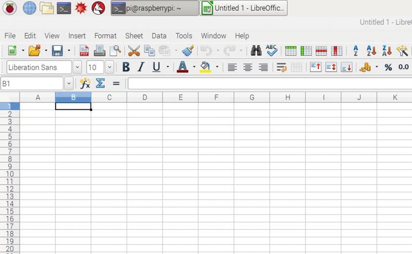
Raspberry Pi GUI with Spreadsheet
For the purposes of this book, the authors will focus primarily on how to connect sensors to the Raspberry Pi and get data out of them. There are many other uses for the Raspberry Pi that will not be covered in this text.

GPIO Pins on the Raspberry Pi
The GPIO pins include several 5 V, 3.3 V, ground, and input/output ports.
There are several special ports on the GPIO pins. These are very important for the Raspberry Pi to communicate via Serial Peripheral Interface (SPI) protocol with other devices like an analog to digital converter (ADC). For the Raspberry Pi 3, pin 23 is the GPIO SPI clock connection; this is also called GPIO11. The next two special connections are pin numbers 19 and 21. Pin 19 is the data in connection termed Master Out Slave In (MOSI), also called GPIO10. Pin 21 is the data out connection termed Master In Slave Out (MISO), also called GPIO9. The final connection is pin 24 and it is the chip enable (CE0) connection. There are a lot of confusing descriptions and diagrams on the Internet regarding these connections, but once the authors understood what these four connections were used for, it started making sense.
Many resources are available online, and the following books were helpful in explaining the Raspberry Pi and its features. Beginner’s Guide to Raspberry Pi published by BDM Publications, Raspberry Pi: The Complete Manual published by Image Publishing, Learn Raspberry Pi Programming with Python published by Apress, and The Python Coding Manual published by BDM Publications are good resources.
GUI: Graphical user interface, a user interface that allows interaction with computers or other electronic devices through graphical icons or visual pointers.
HDMI: High-definition multimedia interface is the standard connection for high-definition (HD) and ultra-high-definition (UHD) equipment.
Debian Linux: Operating system that is similar to Linux and is composed entirely of free software. The group which maintains it is called Debian.
Python: A programming language for general-purpose programming that was created in 1991 by Guido van Rossum.
Raspberry Pi IDE: Some of the graphics in this book may show the Python 3.5.9 interface; others show the Thonny interface which has Python 3.7 embedded in it.
Tkinter: This program or module is included in Python and is a great tool to develop GUIs for the Raspberry Pi.
sudo raspi-config: Command typed into the terminal that opens the rasp-config tool. In this tool, the user can select the one wire, Inter-Integrated Circuit (I2C), or SPI protocols for connecting with remote devices (Figure 1-8).

Raspi-config
Terminal: Program where commands are typed in to execute on the Raspberry Pi (Figure 1-9).
Picamera: Refers to a Raspberry camera computer code module. Figure 1-9
Terminal Interface
Lessons Learned About the Raspberry Pi
Keyboard configuration: The reader may find when they first start out and type a command in on the keyboard that the wrong character may show up on the screen. In the authors’ case, the Raspberry Pi 3 was configured for a keyboard in a different country. To fix this, the reader should visit the Stack Exchange site as most likely the keyboard is set for a UK version. US or other countries’ keyboards have a slightly different mapping arrangement.
This site has more info on this change: https://raspberrypi.stackexchange.com/questions/236/simple-keyboard-configuration.
An important lesson the authors learned is that the Raspberry Pi 3 power supply needs to deliver the correct amount of current required. The authors needed two power supplies: one for the touchscreen and one for the Raspberry Pi. The touchscreen power supply did not put out enough current for the Raspberry Pi and caused it to crash often.
Timing issue: You may notice that if you want precision control of timing, the Raspberry Pi program may be off by a few milliseconds. This is partially due to Raspberry Pi not being a real-time system and partially due to Raspberry Pi’s Linux-derived operating system (OS) overhead. You can find many examples of real-time systems in the real world. One example of a real-time system is how a microwave, when the door is opened, immediately shuts off so that the person operating it is not exposed to harmful microwaves. Real-time systems have to be able to react rapidly to interrupts. This is different from a personal computer, generally known as general-purpose system, an OS where interrupts don’t take priority due to how the chipset is designed. General-purpose systems provide multiple functions which take some minimum amount of time to execute. All general-purpose OSs have some form of overhead that comes in various forms from longer boot-up time to latency between receiving an interrupt event for a new unscheduled task. The Arduino operates closer to real time, so if the reader needs to know the time data is taken, then they might want to consider using the Arduino instead of the Raspberry Pi.
One other key difference between the Raspberry Pi and the Arduino is the voltage needed to power them. The Raspberry Pi uses 5 V DC. The Arduino can use 9–12 V DC. It is critical not to use a power supply meant for an Arduino on a Raspberry Pi; it will damage it.
Unlike the Arduino, the Raspberry Pi does not have a built-in analog to digital converter. Therefore, when using analog sensors, the reader may need to place an analog to digital converter between the sensor and the Raspberry Pi.
- The Raspberry Pi will need to be configured for either an I2C device or Serial Peripheral Interface (SPI). The following steps can configure the Raspberry Pi for I2C or SPI:
Run sudo raspi-config in the terminal window.
Use the down arrow to select 5, Interfacing Options.
Arrow down to P4 SPI or P5 I2C.
Select yes to enable the correct protocol.
Many Raspberry PI programs use modules. Some of these modules are included in the Python code like Tkinter. This is used in the astrophotography project. Other modules are not included, in particular, Adafruit_GPIO.SPI and Adafruit_MCP3008, which are used in several projects in this book.
When installing modules like Adafruit_GPIO.SPI and Adafruit_MCP3008, the user must ensure they are installed in the correct folder. Use pip3 or pip2 depending on the version of Python on the Raspberry Pi.
The Raspberry Pi may come with an SD card with the operating system. However, the reader may download the operating system and install it on an SD card. When formatting an SD card for the Raspberry Pi operating system, run the Guiformat program to create an exFAT (also known as 32-bit FAT) SD card and leave all options at default. This web site has some helpful info:
www.raspberrypi.org/documentation/installation/sdxc_formatting.md.
Finally, the authors used two different programming tools on the Raspberry Pi. They are Python3 and Thonny. They seem to behave very similar and have very similar graphical user interfaces.
Basic Electronics Definitions
The projects in this book include some basic electronic methods and devices. The following definitions may be useful if the reader is new to electronics:
Current: Flow of electrons in a circuit. Units are in amps or milliamps.
Integrated circuit: The integrated circuit ushered in the modern era of electronics. The concept is adding components to a single device which decreases size, increases speed, and lowers the cost of manufacturing. The Arduino and Raspberry Pi have several integrated circuit chips on them.
Resistor: Device that resists the flow of electrons in a circuit. Units are in ohms. The symbol is an omega (Ω). The force sensor used in this book is a variable resistance device that as the force is increased, the resistance decreases.
Transistor: This component is key to most modern electronics. Several of the temperature-measuring devices used in this book are a transistor. They normally have three connections: power, ground, and signal. As the temperature changes, the signal output changes proportionally.
Voltage: In order for current to flow through a circuit, there needs to be difference of energy. The measure for this is voltage, and the normal symbol is V.
Summary
This chapter provides some basic information about two very powerful technology tools: the Arduino and the Raspberry Pi. The reader may want to refer back to the “Lessons Learned” sections if they run into any problems using the devices. Additionally, there is a lot of information online and answers to specific questions, along with user groups and maker spaces that can provide the novice Arduino and Raspberry Pi user answers to their questions.