
The objective of this chapter is to gain insight into how light provides us with heat and when reflected off the moon or other celestial objects provides beautiful images. With regard to the latter, this chapter teaches novice astronomers how to develop a modern, automated imaging system for a telescope through two projects.
The first project demonstrates how to use an Arduino with a unique light sensor to gain an understanding of radiation heat transfer. The second project uses a Raspberry Pi and its camera to capture unique images to study the moon and several planets.
These concepts associated with light and imaging will provide inspiration and guidance for novice astronomers and heat transfer engineers, who would like to improve their ability to measure energy in light or capture images of the moon, planets, and other celestial points of interest.
Radiation Heat Transfer
Most of the heat comes to our planet from the sun via light and the radiation method of heat transfer. On a cold morning, it feels very nice to stand in the sunlight. There is a lot of heat energy in sunlight, and it is mostly transmitted via the visible and infrared wavelengths of light. This project uses a very unique sensor along with the Arduino to measure both infrared and visible light.
Develop an understanding of light and radiation heat transfer.
Using the Arduino and a unique light sensor to capture light intensity.
Conversion of radiation data to Lux in the code and estimation of radiation heat transfer directly from the sun or through a window with a reflective coating.
This project utilizes a very unique new sensor from Adafruit, the TSL 2591. It uses two photodiodes to measure various wavelengths of light. One photodiode is sensitive to infrared only, and the other is sensitive to visible light, infrared, and the full spectrum of light. This incredibly low-cost device then compares and integrates those measurements to calculate Lux (which is defined as lumens/square meter) and outputs values for visible and infrared light.
The purpose of this experiment is to estimate how much heat via radiation from the sun is transferred into a house through a window.
Arduino Uno
Adafruit light sensor, TSL 2591 luminosity sensor
Window
Optional: Reflective window covering material
Miscellaneous wires and proto-board
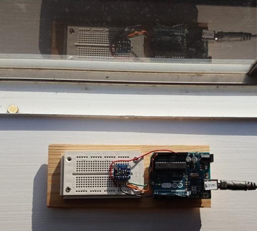
Open Window
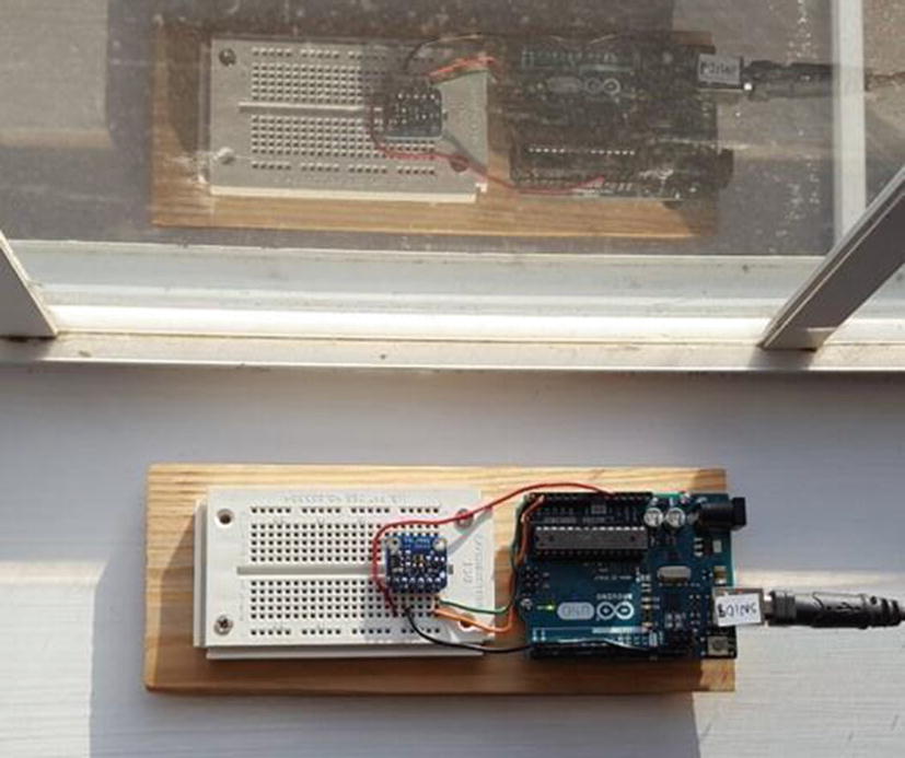
Closed Window
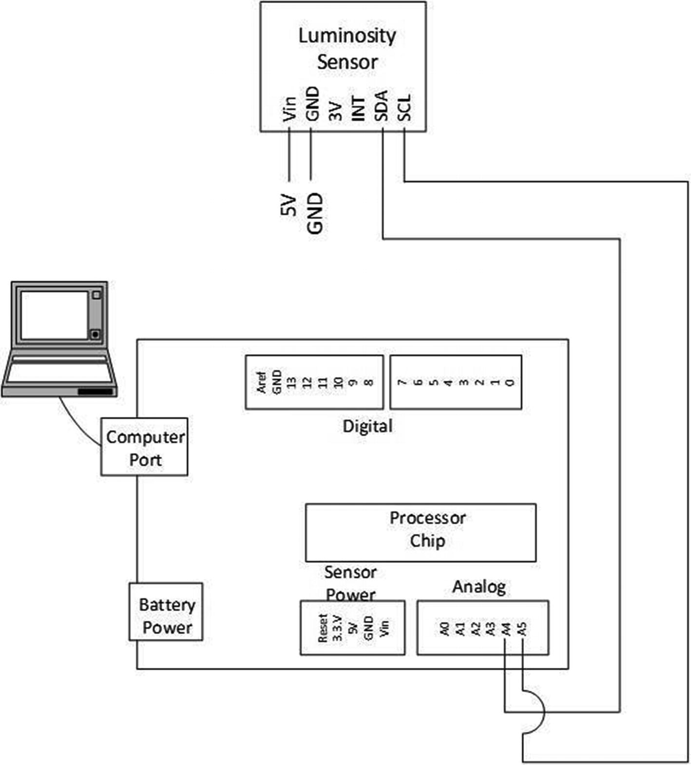
Light Sensor Schematic
Listing 7-1 has only very slight modifications to fit in this book. It is also configured to accept bright light. The new TSL 2591 sensor and this code work very well. It is a very amazing device to measure light in all kinds of conditions.
The Adafruit_Sensor.h and Adafruit_TSL2591.h libraries are needed for this code.
The code that is bold below is on one line and should not overwrap when typed into the IDE.
Arduino SN108_TSL2591 Light Sensor Code
Example Radiation Heat Transfer Data
Configuration | Avg IR | Avg Visible | Sum of IR + Visible | Improvement with Covering |
|---|---|---|---|---|
Raw sunlight | 1991 | 2772 | 4763 | |
Window w/ reflective covering | 503 | 927 | 1430 | 70% reduction |
Analysis of Heat Transfer
The authors then used the preceding data to develop an analysis of the heat transferred through a window. This can be used to do design trades of the number and size of windows. Another study could look at which direction a building or home faces and how many windows are located on the south-facing walls.
dq/dt = (1000 W/m2) ϵ A cos Ѳ
dq/dt = (Window Reduction Factor) (1000 W/m2) ϵ A cos Ѳ
Window Reduction Factor = (1 -0.7) = 0.3 from observations
ϵ = 0.96 for a white-painted surface
A = 1 m2 using a square meter which can easily be scaled up or down for larger or smaller areas
Assume a 30-degree incidence of light hitting the window.
dq/dt = (0.30) (1000) (0.96) (1) cos 30 = 249 watts for one m2
dq/dt = (1000) (0.96) (1) cos 30 = 831 watts for one m2
Taking this analysis one step further for a large house with six windows that are 2 m2, the heat transfer rate would be, at this time of day with this angle of incidence, 6 × 2 × 831 watts, or approximately 10,000 watts. That is a lot of heat entering through those windows.
Adding the reflective coating reduces that to 3000 watts which is a lot less but still quite a bit of energy.
Engineers can use analysis like this to ensure the air-conditioning system is sized properly and provides adequate cooling on hot days.
Radiation Heat Transfer Recap
The preceding data shows how beneficial from a heat transfer perspective using windows with reflective coatings can be to reduce the amount of solar radiation (heat) that enters a window. It can also be utilized to estimate the amount of heat contribution and develop changes to the number and size of windows when designing a building or house.
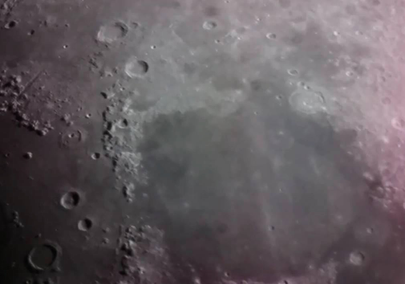
Astrophotography with the Raspberry Pi Camera
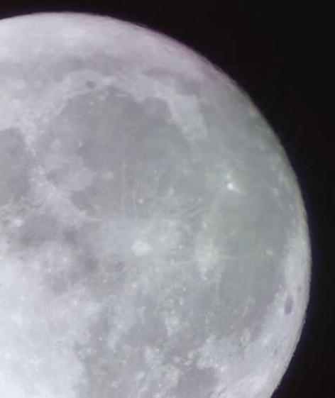
Image the Authors Captured of the Moon with Raspberry Pi and Telescope
This final project shows how to attach the Raspberry Pi to some older telescopes to convert them to nice modern imaging machines. The first subsection shows how a Raspberry Pi camera system can be added to a Meade ETX-60AT telescope. This is a very nice little scope that has a controller and a drive system that will keep it tracking the object despite the Earth’s rotation. The second subsection attaches the same Raspberry Pi camera system to a standard 4 ½-inch reflector telescope.
Develop an understanding of astronomy, the moon, and planets.
Using the Raspberry Pi and its camera along with telescopes to gather images of astronomical items. Planning and building a complex system. Learning how to use a 3D printer.
Develop an understanding of how mathematics is used to ensure multiple assemblies fit together.
This section is a great example of the difference between engineering and science. The majority of this section covers the engineering needed to develop this unique combination of modern Raspberry Pi technology with two different older telescopes. These devices are then used by the scientist to explore astronomy, gather data, and capture beautiful images of the moon and the two largest planets.
The first subsections describe how to do the setup of the Meade ETX-60AT telescope and the 4 ½-inch reflector telescope. They also highlight the code that operates the cameras to take both still images and videos. The later subsections show how to build the components for these complex but very useful devices. In the “Appendix” section, there is information regarding the Meade ETX-60AT telescope. This telescope is no longer available from the manufacturer, but the reader may be able to obtain one on eBay or some other similar telescope.
The section “Astrophotography with the Raspberry Pi Camera” is presented in reverse order; it may be confusing at first, but the reason for this is to help the reader understand the final goal first and then explain how the authors reached that goal. The objective of this project is to set up an astrophotography telescope system that is adaptable to different telescopes and easy to use.
7.2.1: Assembling the Meade ETX-60AT and Raspberry Pi
7.2.2: Assembling the 4 ½-Inch Reflector Telescope and the Raspberry Pi
7.2.3: Basic Raspistill Previewing an Image with the Terminal Command Line
7.2.4: Astrophotography Raspberry Pi Python GUI
7.2.5: Assembling the Raspberry Pi and Touchscreen in the Case
7.2.6: Camera Modifications, Camera Case, and Power Cables
7.2.7: Building the Shelf for the Meade ETX-60AT
7.2.8: Helpful Hints Using the Telescope and Raspberry Pi
7.2.9: Example Images and Enhancing Them Using a Video Capture GUI
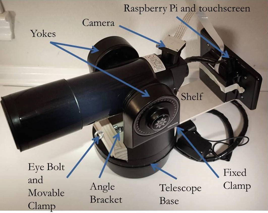
Assembling the Meade ETX-60AT and Raspberry Pi
The individual pieces (telescope, Raspberry Pi/touchscreen/case, and the shelf) have their own sections later that describe them. The following diagrams in this section show how the major pieces are assembled.

Top View of the Shelf and Raspberry Pi
Assembled Raspberry Pi, Shelf, and Telescope
- 1.
Insert AA batteries into the telescope (Figure 7-7) in accordance with the telescope instructions. Because of their location, under the shelf, the batteries need to be inserted first.
- 2.
Attach the Raspberry Pi 3 and case to the shelf (Figure 7-8).
- 3.
Slide the shelf through the telescope yoke (Figure 7-9).
- 4.
Place the movable clamp against the front of the yoke and screw in the eye bolt through the movable clamp into the RIVNUT angle bracket (Figure 7-9).
- 5.
Tighten the eye bolt until the clamp secures the shelf in place.
- 6.
Insert the Raspberry Pi 3 camera case into the telescope eyepiece (Figure 7-10).
- 7.
Follow the Meade telescope setup instructions to enable star tracking. Now it is ready to start capturing beautiful images!

Battery Installation in Meade Telescope
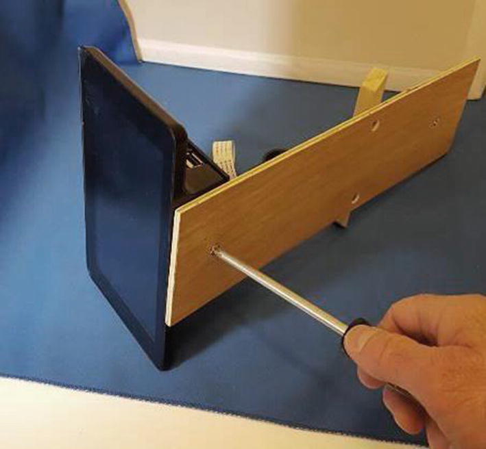
Attaching Raspberry Pi to Shelf

Tightening the Clamp with the Eye Bolt
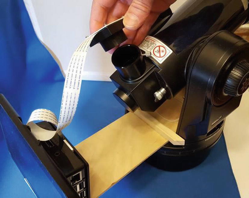
Insert Pi Camera Case into Eyepiece
Astrophotography Meade ETX-60AT Setup Recap
The small size of the Meade ETX-60AT with the Raspberry Pi attached to it is perfect for an amateur astronomer as it can be left set up. It has a small footprint, takes a small space, and is ready to go at a moment’s notice!
Assembling the 4 1/2-Inch Reflector Telescope and the Raspberry Pi
This section shows the same Raspberry Pi system mounted to a different telescope using a body mount method. It uses a system that mounts the Raspberry Pi 3 using a 5-inch hose clamp and a few pieces of ½ × 3/16-inch wood to the body of the telescope tube. The Raspberry Pi 3 and touchscreen were too heavy to body mount to the Meade ETX-60AT as the motors were not strong enough to move it. However, it works very well on this non-powered old reflector telescope.
The following images show the greater magnification a more powerful telescope provides compared to the images of the moon from the smaller Meade ETX-60AT. The authors included some other images here too from this old telescope and an explanation of how they accomplished them. Then enhancement is provided in the section “Example Images and Enhancing Them Using a Video Capture GUI.”
Moon: Sea of Serenity Image from 4 ½-Inch Reflector, April 8, 2018

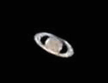
Saturn from 4 ½-Inch Reflector, April 11, 2018

Enhanced Saturn Image from 4 1/2-Inch Reflector, April 25, 2018
Enhanced Jupiter Image from 4 1/2-Inch Reflector, May 4, 2018
Components Needed to Assemble the Raspberry Pi 3 Mounting System to the 4 1/2-Inch Telescope
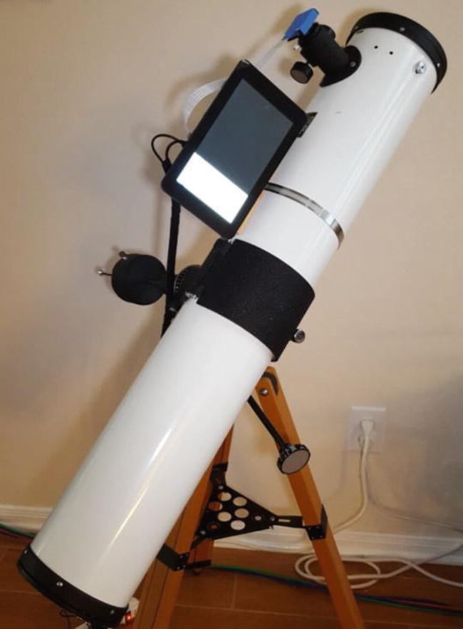
4 1/2-Inch Reflector with Raspberry Pi

Hose Clamp for Body-Mounted Raspberry Pi 3

Close-Up of Body-Mounted Version

Body-Mounted Raspberry Pi System

Parts for the Body Mount System
Sighting this telescope on a distant planet like Saturn is a little difficult. The authors found it best to find it first with the eyepiece, then remove it, and insert the Raspberry Pi camera to get the image. Due to the Earth’s rotation, the image moves rather quickly across the telescope’s view, so the astronomer will need to install the Pi camera and take the image quickly.
After adding the Raspberry Pi and camera, the 4 1/2-inch reflector telescope is now set up and ready to take some pictures of the larger planets.
Reflector Telescope Setup Recap
Turning these two older telescopes into modern astrophotography machines was a real joy. The next sections detail first a simple method without programing to start taking images. Later sections detail how to program two GUIs for easy picture and video captures. The final sections provide details on building the complex shelf set up to attach the Raspberry Pi to the Meade ETX-60AT.
Basic Raspistill Previewing an Image with the Terminal Command Line
If the reader is not interested in programming the Raspberry Pi, these first methods using built-in tools and simple commands in the terminal are perfect for using the system right away. Later sections provide code that creates a nice GUI. One other use for Raspistill is to test the Raspberry Pi camera and the telescope system to make sure it is functioning before starting to work on the GUI described in later sections.
The first method that the authors used to capture images is the onboard program named Raspistill. Todd Franke provided the info on how to use this very useful tool.

Raspistill Typed into Terminal Command Line
Figure 7-20 previews an image for an extended period of time. In this example, the program previews images for 100,000 milliseconds (i.e., 100 seconds) or a little more than 1 1/2 minutes. If you just want to show the image to others, this might be a nice long view.
If the astronomer is planning to take a number of photos, this might be too long, and the time can be shortened. If no time is specified, it previews for 5 seconds.
Having the preview for an extended period is a great way to focus the telescope. In the case of the Meade telescope, the focus knob is at the end of the body tube and moves the front lens forward and backward.
Using Raspistill to Capture an Image
Raspberry Pi 3 saves an image with the name cam.jpg. The following site provides additional information regarding using Raspistill including how to add a time stamp to the image captured:
www.raspberrypi.org/documentation/usage/camera/raspicam/raspistill.md
More Advanced Raspistill Input Without a Keyboard
The authors also came up with a way to input the commands using only a mouse. This is a lot less awkward outside at night during an observation session. It requires some setup time prior to the observation session. The astronomer uses either the simple text editor or a program on the Pi called Libre Word Processor. Use these programs to set up the Raspistill commands in a file. Using only a mouse, the astronomer can open the document file and then highlight, copy, and paste the text command into the command line. This capability simplifies and reduces commanding time. The no-keyboard configuration may also make it easier to operate outside during an observation session.
- 1.
Save the document on the Raspberry Pi desktop.
- 2.
Open the document.
- 3.
Open the terminal command line.
- 4.
Copy and paste the line and the line break into the command line in the terminal program.
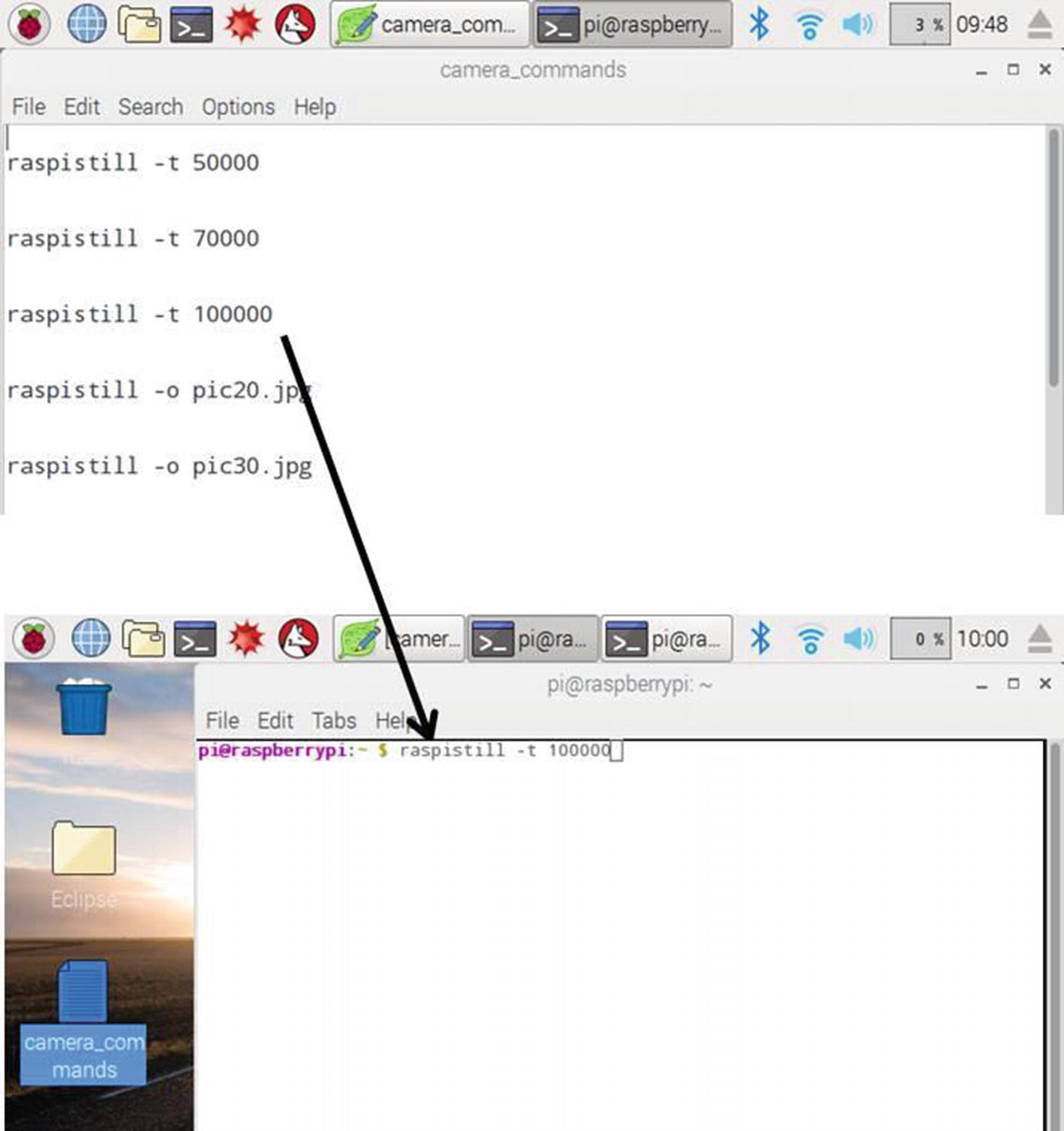
Copy and Paste Commands into Script Line
The first two of these commands turn the preview on for 10,000 or 70,000 milliseconds, which is equivalent to 10 or 70 seconds. The 70 seconds is probably needed to focus the object. The 10 seconds is enough to look quickly before taking a picture and to ensure the object is still in view or in focus. The next two commands take a picture. It names the file image pic20.jpg or pic30.jpg.
The astronomer will need to change the file name or move these files from the Raspberry Pi, or the Raspistill will overwrite them the next time you run these lines of code.
The astronomer can insert his/her own code into the command file if some other name is desired.
Raspistill Image Capture Recap
Since the Raspberry Pi is a full-blown computer, there are already built-in tools that the reader can access and use. If the reader would like to automate taking images, the next section provides code to develop a GUI using the built-in Tkinter module.
Astrophotography Raspberry Pi Python GUI
The authors wanted to minimize working on coding, yet provide an easy way to operate the Raspberry Pi 3 camera and functionally provide great images, such as that shown in Figure 7-4. There are sites that provide excellent information regarding GUIs and the Raspberry Pi 3 camera, and they can aid in minimizing programming and provide useful and easy methods to operate the telescope with a Raspberry Pi 3. For other astronomers who are interested in more intricate or elaborate coding, there are sites that may provide starting points to develop their own version.
The following site provides the astronomer with a good basic understanding of how to set up a GUI to command the Raspberry Pi 3 to perform a desired function and was the starting point for the authors’ code in Listing 7-2:
http://robotic-controls.com/learn/python-guis/basics-tkinter-gui
This site contains a very impressive GUI design for operating the Raspberry Pi camera, for those who want to adjust and manipulate the image:
www.raspberrypi.org/forums/viewtopic.php?t=47857
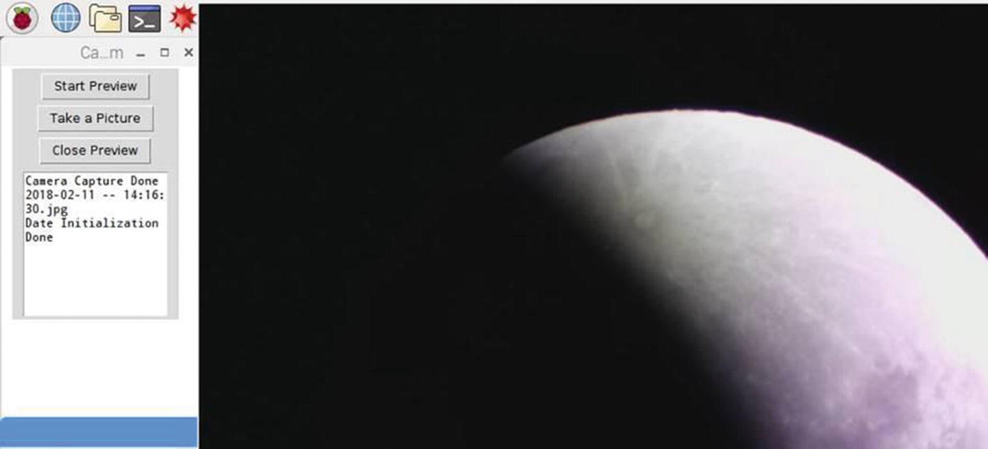
GUI for Raspberry Pi Camera
- 1.
The first part is setting up the Tkinter main window and camera basic functions.
- 2.
The second part of the program initializes the widgets that run the commands when you click the buttons.
- 3.
The third part configures how the window should look. Once that is complete, root.main loop () starts up the program and will not run or load anything after that point.
Raspberry Pi Code PI_SN003_Astrophotograhy_Image Capture
The light-gray numbers at the start of the line represent the line of code and are not in the program.
Make sure this code is saved in a file as “your file name here.py” for Python and saved in the main folder.
Initiating the GUI
- 1.
Open Programming and then open Python.
- 2.
Open the file that contains the preceding program.
- 3.
Open Run and then Run module.
The authors learned these tips and tricks while developing this code.
sets the location of the GUI at 200 × 1100 pixel sizes. It is the window size, and +0+0 is the x–y position using pixels again. The code may need to be adjusted to move the location to a different one. The authors wrote this code to match the 7-inch touchscreen. For other monitor sizes, the programmer may need to change the position and size to fit.
The authors found that the touchscreen can be used to take a picture, but it might set up a vibration and potentially blur the image. Using a wireless mouse prevented that from happening.
PI_SN003 Raspberry PI GUI Recap
This program PI_SN003 is very easy to use during an observation session. It lets you observe the object constantly, and then when the perfect image appears, with a simple click of the mouse you capture a fantastic image!
Assembling the Raspberry Pi and Touchscreen in the Case
There is a bit of engineering required to develop the system that connects the Raspberry Pi to the Meade ETX-60AT. The first part is the housing and touchscreen which is a nice package for the system. The second part shows how to 3D print the Pi camera case. The final part is the shelf bracket that grips the telescope and holds the Raspberry Pi/touchscreen assembly.
Raspberry Pi, Touchscreen, and Case
This section describes the assembly of the Raspberry Pi, touchscreen, and housing for them. One of the key features for this project is the touchscreen to show the image to ensure it is in focus. The 7-inch screen is an excellent choice for this application, as it is large with good contrast and definition. The authors found a case they liked that nicely integrated the touchscreen and the Raspberry Pi 3. It was also easy to modify the case with a single hole and add a RIVNUT to attach it to the shelf.
Raspberry Pi 3 Model B (≈$25)
Raspberry Pi 7-inch touchscreen (≈$80)
Raspberry Pi camera V2 (≈$30)
Premium case for Raspberry Pi 7-inch touchscreen (≈$17); Digi-key part#: ASM-1900035-21
Camera cable, 12 inches long (≈$2)
Two 5-volt Raspberry Pi power supplies with a micro-USB connector (≈2 × $7.50)
Cable wrap to combine power supply cords ($3)
8-32 RIVNUT
8-32 × ¾ flat head screw
Total cost ≈ $185
For remote operations where there is no power, the reader may want to use a power inverter. It is a device that plugs into a lighter connection in a car and changes the DC to AC and can power the Raspberry Pi and touchscreen. The authors needed this device to capture the eclipse images. The model used was the remote operations power inverter ($35), Wagan Tech part number: SmartAC 200 USB+.
Modification of the Case and Assembly
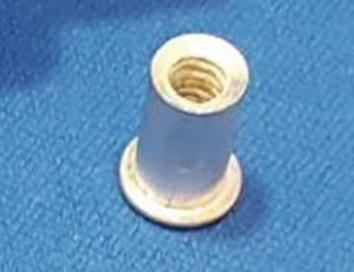
RIVNUT

RIVNUT Installation Procedure
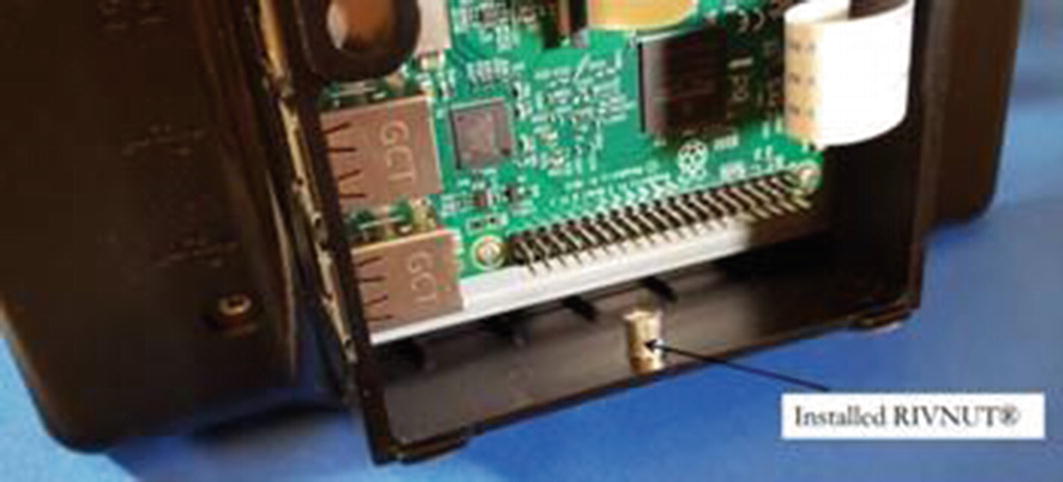
RIVNUT Installed in the Case
An alternative to the RIVNUT approach is to simply glue a small nut inside the case using epoxy. This should be adequate to apply enough torque to secure the Raspberry Pi to the shelf.
One other important aspect is to apply tape over the end of the RIVNUT. This will catch any potential metal shavings when the screw is threaded into the case, clamping it down. Metal shavings could potentially short out circuit paths or connections which could damage the Raspberry Pi.
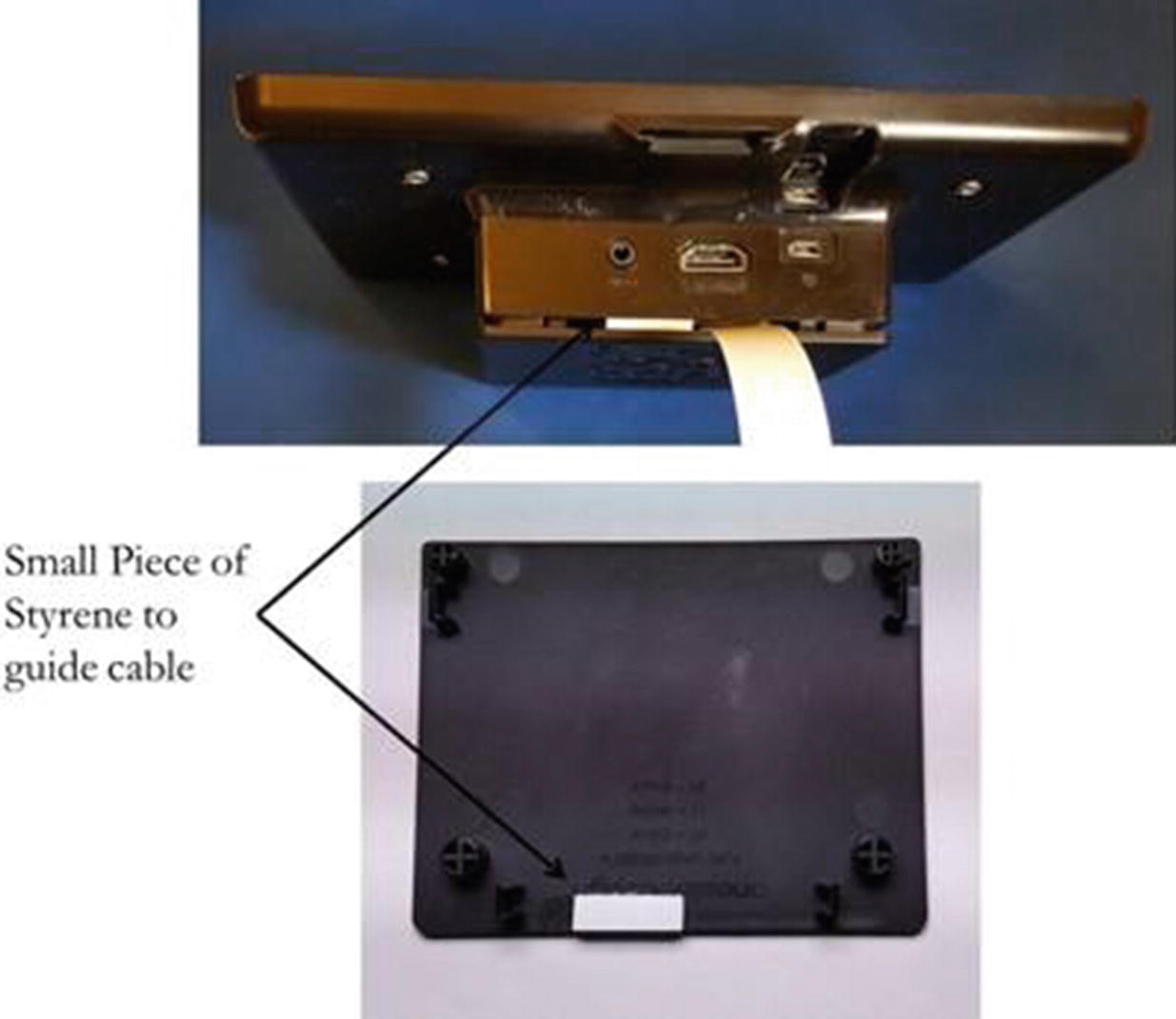
Modification to the Case Backplate
The case comes with instructions regarding this modification to the Raspberry Pi 3 setup.
Components and Assembly of the Raspberry Pi Case Recap
This case was perfect for this application; it had a great place to use for mounting to the shelf and contained the touchscreen and the Raspberry Pi. It has been used on many observation outings with no issues.
Camera Modifications, Camera Case, and Power Cables
The telescope becomes the lens for the Raspberry Pi camera, so the lens that comes with the camera must be removed. This section also describes making the camera case using 3D printing and the final assembly of the camera/case.
Camera Modifications

Removing the Lens from Pi Camera
Building the Camera Case
3D printing is an awesome technique that provides a unique way to create many different shaped parts. This is similar to the replicators in the original Star Trek series. Many creator spaces online can help a person develop parts using the 3D printing process. Mitch Long was very helpful in showing the authors how to create these camera cases.
The first step is to use computer-aided design (CAD) software to create a virtual model. The next step is to load that model in the correct format into the 3D printer, which uses a device that heats a material so that it flows easily. It precisely controls laying the melted material, layer upon layer, leaving voids in accordance with the input model, and gradually shaping the object until completion in each dimension. Hence, the process actually creates a 3D hardware object using a procedure that is partially analogous to ordinary paper printing.

Camera Case for Raspberry Pi, Ready for 3D Printing
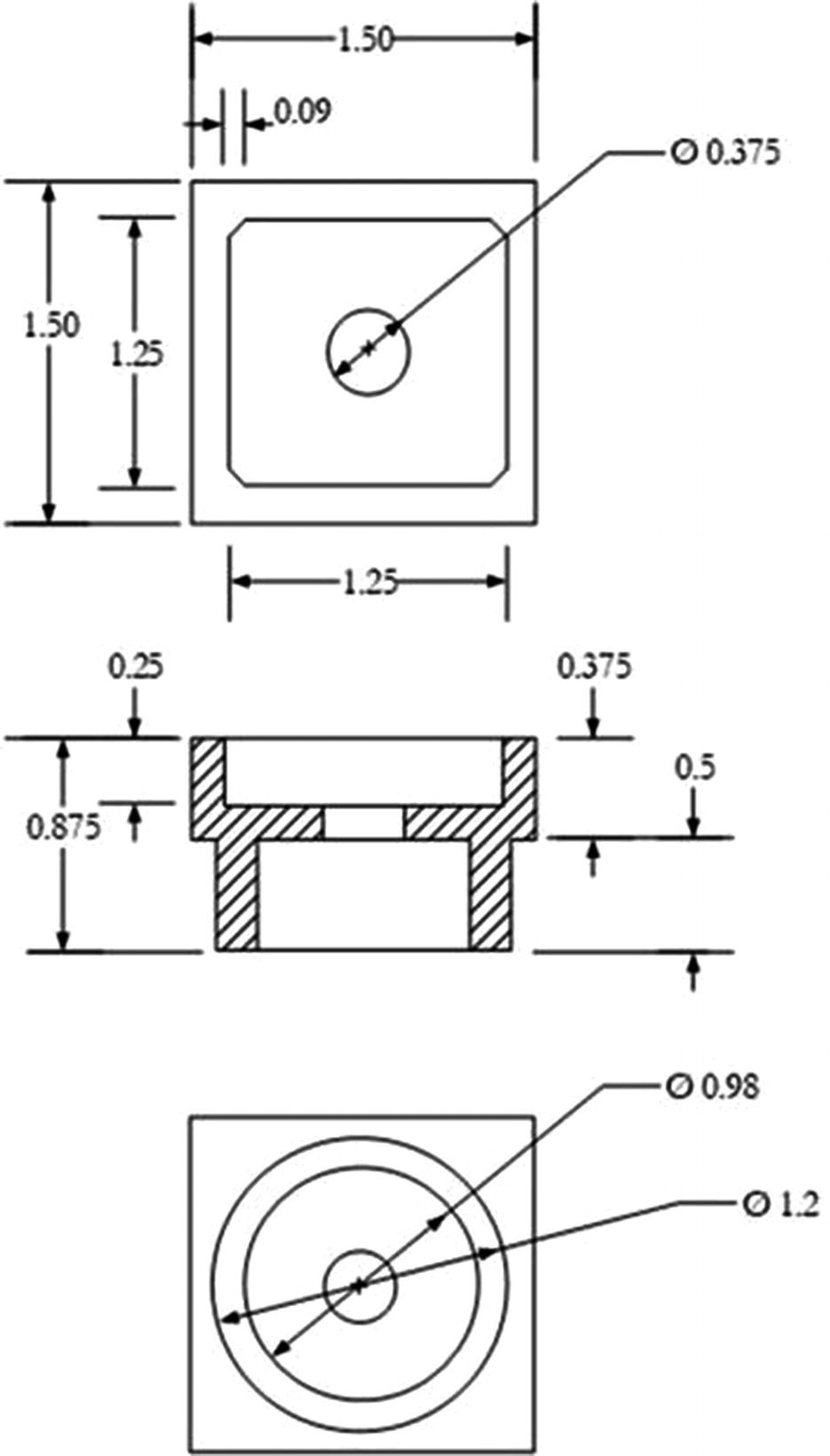
3D Printed Camera Case (Dimensions in Inches)

3D Printer: Camera Case Taking Shape
Cleaning Up the 3D Printed Camera Case

Camera Case Cover (Dimensions in Inches)
Drilling Screw Holes in the Camera Case
Tapping the Screw Holes in the Camera Case
The authors have uploaded their Pi camera case to Thingiverse, which is a repository of 3D files. The authors created both a version for the Meade ETX-60AT (1 ¼-inch diameter) and the 4 ½-inch telescope (1-inch diameter). The files are located at the following site:
www.thingiverse.com/thing:2885450
Figure 7-28 shows the image of the camera case in the CAD program.
The dimensions for the camera case are shown in Figure 7-29.
Drawings in this book may not be to scale.
The camera case is starting to take shape in Figure 7-30.
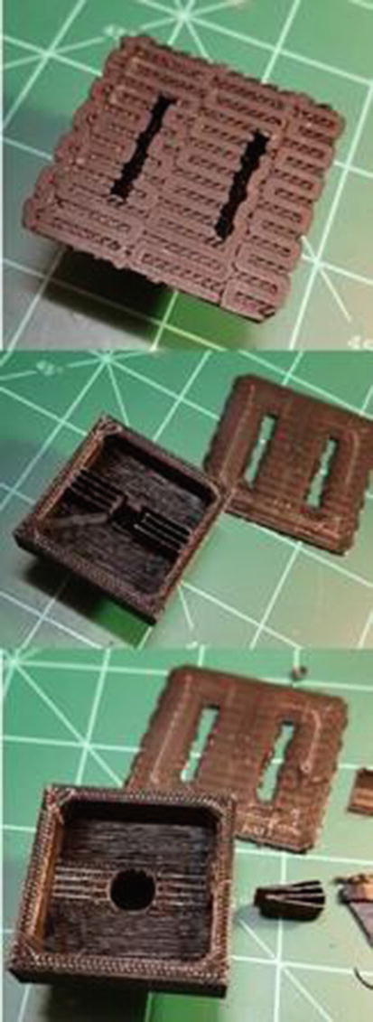
The material used to print the camera case was standard black PLA (polylactic acid) which is a common material for 3D printers. The MakerBot slicer software sets up the file for 3D printing. The slicer software used by the authors is CURA. A few parameters are set that relate to the fill and the supports. To minimize material, the shape is mostly hollow. The fill percentage creates a honeycomb structure inside the shape. The authors set it at 20% since it will be drilled and tapped. Typically the fill is set at 10%. Another setting that was selected is to add supports; these keep a section with nothing under it from collapsing as it cools. The supports will need to be removed after the shape is finished printing as seen in Figure 7-31.
If the reader does not have access to a 3D printer, there are several companies that will (for a fee) print out an object. Shapeways is one: www.shapeways.com.
Figure 7-31 shows how the case comes from the printer and the items that need to removed. The first step is to remove what is called the raft. It is the plate that the 3D printer puts down first and ensures the print has a solid base to prevent warping. The next step is to remove the supports which were located in the square box of the camera case.
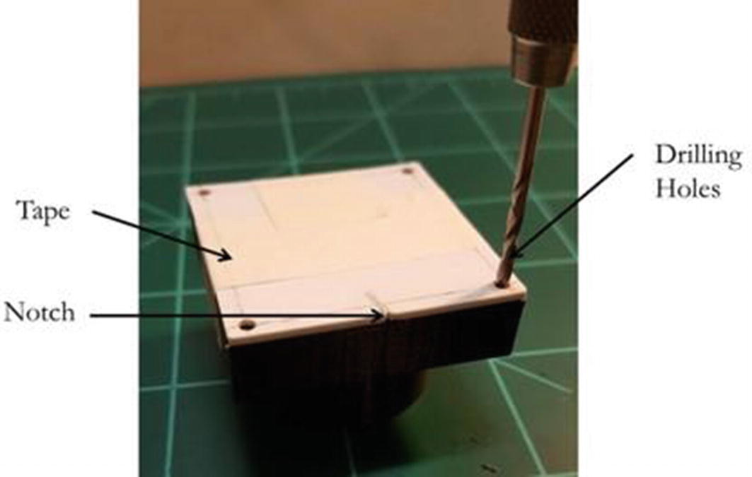
To finish the camera case, cut a small styrene sheet (0.030 inches thick) of plastic 1 ½ × 1 ½ inches square (Figure 7-32). Draw lines that guide where the holes will be drilled. If you use the authors’ 3D case on Thingiverse, the holes should be approximately 0.095 inches in from the edge.
Tape the cover in place on the camera case (Figure 7-33) and drill through the cover plate, keeping the drill bit perpendicular to the plate. When the drill penetrates the cover plate, it leaves a mark where the hole will be drilled in the case. The reader can use extra 2-56 tap drill bits to help with alignment by placing them in each hole as it is drilled to keep the parts lined up. Otherwise, make sure the tape keeps the plate from shifting when drilling the next hole.
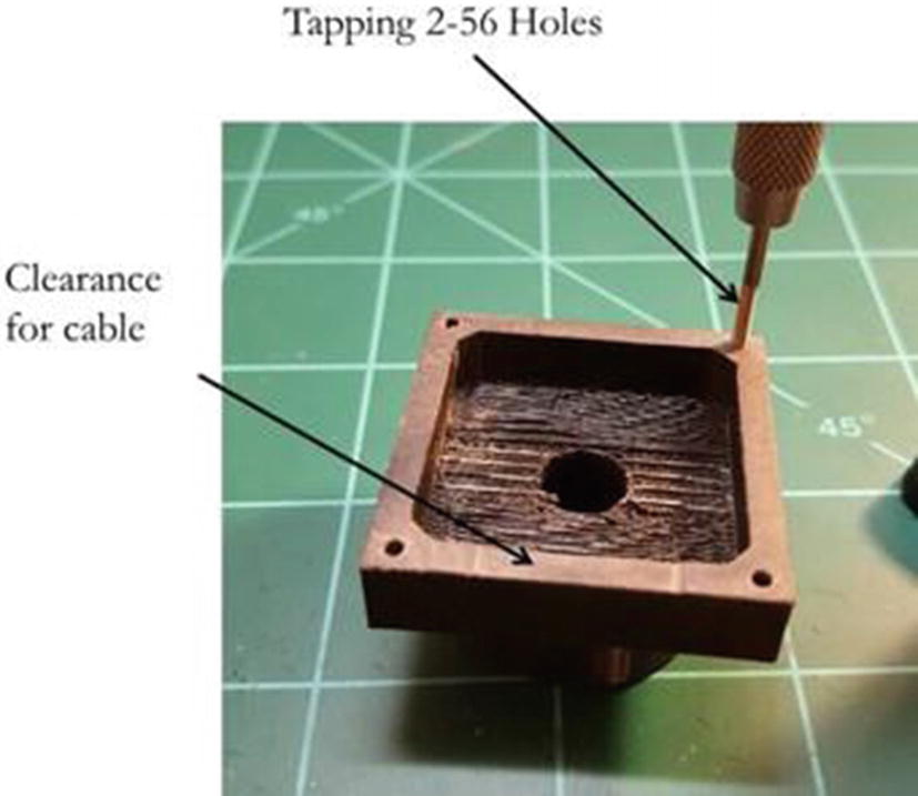
The authors cut a small notch in the cover and the case to guide the assembly. This is done while the tape is still in place and helps to ensure the cover can be placed in the correct orientation later, so that the holes line up properly after the tape is removed. Tap the holes using a 2-56 tap. Then the last modification is to file a slight gap for the camera cable to pass through. See Figures 7-33 and 7-34.
Final Assembly of the Camera in the Case

Foam Tape on Raspberry Pi Camera
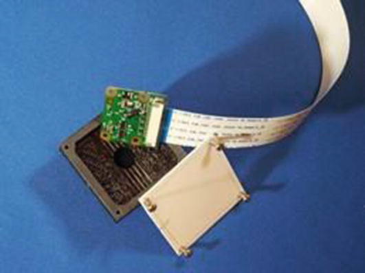
Final Assembly of Camera into Case
However, if the astronomer does not want to utilize 3D printing for the camera case, the following web site describes a unique way to build up a similar case using a large modified SD card case and a piece of PVC pipe to construct it:
Power Cord Combination
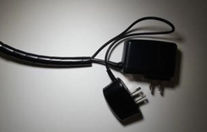
Power Cable Wrap
Camera, Camera Case, and Power Cord Assembly Recap
This section outlines all of the changes needed to set up and assemble these key components for the Raspberry Pi astrophotography system.
Building the Shelf for the Meade ETX-60AT
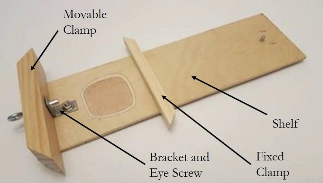
Assembled Shelf

Shelf Pieces
The shelf assembly is made up of the subassemblies shown in Figure 7-39. Each component will be described in detail in the next few sections. It may look somewhat complex, but it is really straightforward.
As always, safety first when using saws and tools, especially if the reader is not familiar with their operation. Remember to use hearing protection and safety glasses when using power tools such as saws and drills. Inexperienced young astronomers should get assistance from an adult or visit a maker group. These are groups around the country and are set up to aid people who want to learn how to make things.

Areas Modified to Ensure Clearance
Plywood shelf base
Material: 3/16-inch-thick plywood, 3 5/8 inches wide by 13 inches long

Shelf (Dimensions in Inches)
- 1.
Mill out area for clearance.
- 2.
One Raspberry Pi mounting hole.
- 3.
Two holes for the fixed clamp.
- 4.
One hole for the RIVNUT/bracket.
The authors used flat head screws so the holes must be countersunk on the shelf bottom.
Using the Dremel grinder tool, grind or mill out the clearance area, which is approximately 2 1/8 inches square and approximately 1/16–3/32 inches deep.
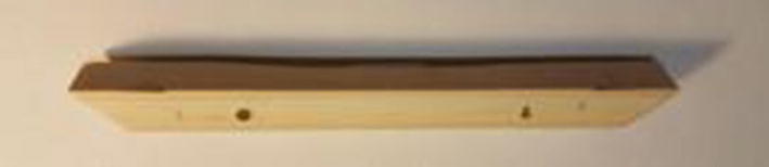
Fixed Clamp
Material: 1/2-inch square wood that is 5 1/2 inches long
- 1.
Cut the ends at a 45-degree angle.
- 2.
Chamfer one edge for clearance for telescope rotation.
- 3.
Drill clearance holes for screws that are 2 1/8 inches apart and match the two holes in the shelf where the fixed clamp is attached.

Movable Clamp
Material: 1 ½ × 2 ½ × 5 ½-inch wood
- 1.
Cut the ends at a 45-degree angle.
- 2.
One hole was drilled that matches the height of the RIVNUT/bracket.
The hole needs to be positioned so the movable clamp is slightly above and not resting on the shelf, so it does not drag when the eye bolt is tightened.
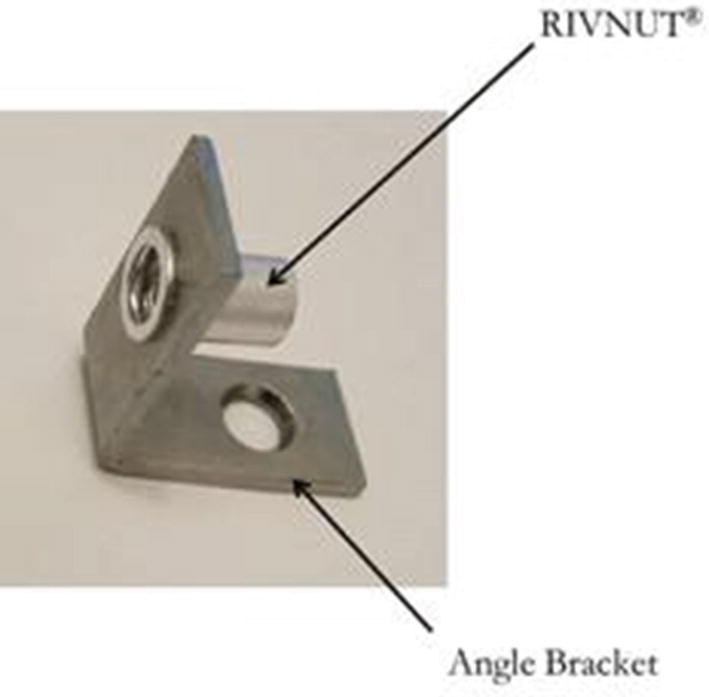
Angle Bracket with RIVNUT
Material: 1 inch × 1 inch angle bracket and RIVNUT
- 1.
The hole in the bracket may need to be enlarged slightly for the RIVNUT to fit through prior to being expanded.
- 2.
Install and expand RIVNUT in the same manner completed for the Raspberry Pi case.
Shelf Components and Assembly Recap
This section provides details on how to fabricate and assemble the shelf and the interfaces between the telescope and the Raspberry Pi. It makes a nice integrated package and is easy to assemble.
Helpful Hints Using the Telescope and Raspberry Pi
- 1.
Always make sure the telescope lens, camera, and the mirror are clean from debris, so that the astronomer captures a good clean image. The authors had several beautiful pictures ruined because of debris on the mirror that sends the image to the eyepiece.
- 2.
If possible, plan ahead and position needed items for easy access. A table, power cords, and a flashlight are very helpful. Also, have the keyboard handy just in case you need to type in commands. The authors had to reboot the Raspberry Pi 3 during one observation session, because it locked up. They resorted to typing in the commands again.
- 3.
If the astronomer copies and pastes commands into the script line, the authors recommend using the simple text editor rather than the word processor. The text editor seems more robust for setting this up, but you need to press “Enter” at the end of the line and make sure that you copy and paste this keystroke into the script.
- 4.
Chairs for the astronomer and any other viewers make this an enjoyable experience.
- 5.
To protect the touchscreen, the authors left the protective film on it. It did not seem to affect the functionality of the touchscreen and image quality, and it protected it from many bumps and potential scratches that occurred during assembly and use of the scope.
- 6.
When doing the Autostar alignment of the Meade telescope, the authors found it helpful to cover the Raspberry Pi 3 screen with a cloth, because it is so bright that it makes it hard to see where the scope is pointing.
- 7.
The authors sometimes accepted the Autostar alignment without verifying it through the eyepiece. If the telescope was in the general direction toward a bright star, then they accepted it. The fine alignment was done on the moon by loosening the yoke and adjusting it by hand.
- 8.
The batteries for the Meade telescope tended to last no more than two or three observation sessions. It may appear as if it is working, but there may not be enough power to operate the motors in the upright yokes. The scope will rotate horizontally, but not vertically. If the astronomer does a lot of observing, she/he may want to invest in two sets of rechargeable batteries, always prepared to swap out discharged with charged batteries.
- 9.
The authors used a power inverter to power the Raspberry Pi for a remote location. Make sure the configuration is tested before going remote, as it may or may not be able to supply enough current to drive the Raspberry Pi 3 and touchscreen.
The astronomer may want to try to power the Raspberry Pi 3 and touchscreen from a battery pack. The following web site explains how the astronomer may want to accomplish this goal. The site indicates the screen requires 500 mA and the Raspberry Pi draws 2.5 amps:
https://raspberrypi.stackexchange.com/questions/49533/powering-the-pi-3-model-b-with-a-battery-pack
On one remote observation session, the authors powered the Pi using an inverter plugged into the car. The inverter supplied a little over 2 amps, but had some surge capability. It worked fine and ran the system during one observation session for about an hour.
- 10.
When focusing the Meade telescope, the primary lens moves up and down the barrel. As an aid, the authors put a piece of tape on the barrel and marked the location close to the normal focus for the moon. This helped to speed up focusing the scope during an observation session.
- 11.
The astronomer may want to do a screen capture at some point. For the Raspberry Pi 3, the command typed into the terminal program is “scrot,” and it will save the image in the main folder with date and time info in the file name.
- 12.
An important lesson the authors learned is that the Raspberry Pi 3 power supply needs to deliver the amount of current required. The authors used one official Raspberry Pi 3 power supply and one random spare supply. It turned out that spare one would not deliver enough current to the Pi. It worked well for the touchscreen monitor. The system would crash often if the wrong power supply was used to power the Raspberry Pi 3. This caused a lot of challenges until the cause of the crashes was determined and corrected.
- 13.
A wireless mouse eliminated one cable and made the system easier to use outside. The touchscreen can be used to activate the “take picture” button on the GUI, but the astronomer may cause a vibration or other movement when using it and potentially blur the image.
- 14.
The authors had some challenges using a flash drive with the Raspberry Pi. It may be caused by the configuration. Normally the files are not too large, so it is easy to email the images. The authors used Gmail to do this on the Pi.
- 15.
The authors found it very helpful to have a program on their personal computer that helps identify the location of the planets and stars. The program Stellarium, used by the authors, is an open source free code that does a great job: http://stellarium.org/.
- 16.
The authors found the following helpful site while researching this project, which contains a lot of great images and information about the moon: www.alanchuhk.com/.
This book does not focus on how to take videos using this system, but there are real benefits for image enhancement using a video. One way to obtain a video is using the program Raspivid which works in a similar way to Raspistill.
Lessons Learned Recap
After several observation sessions, the authors learned several lessons they wanted to pass on to the reader. These items help to make a fun successful observation session and can improve the experience for everyone involved.
Example Images and Enhancing Them Using a Video Capture GUI
The authors also developed a GUI that will take a video (the code is shown later in this chapter). It is a modification to the authors’ camera GUI. It will create a video file with a unique file format that will need to be converted to standard formats. This is described after the video GUI code.
If the astronomer becomes very interested in cleaning up the images, there is a protocol called Planetary Image Pre-processing and image stacking. It requires a video file and does an amazing job of overlapping and correcting images. There is a short overview of these techniques later in this chapter, but significant detail is beyond the scope of this book. The authors thank Jeff Dunehew for providing the process to use videos to create enhanced images. As the astronomer gains skills with their system, this amazing technology can be explored.
Example Images Taken with the Upgraded Meade ETX-60AT Astrophotography System
Moon on January 13, 2018

Jupiter and Its Three Moons on January 29, 2018
With the Raspberry Pi attached to the telescope, you too can capture sequential images over time and observe phenomena such as the motion of Jupiter’s moons as they orbit the planet just like Galileo.
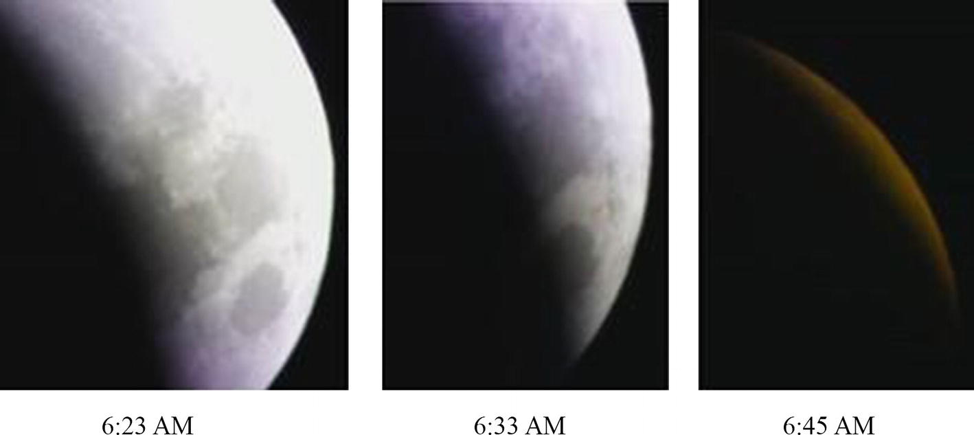
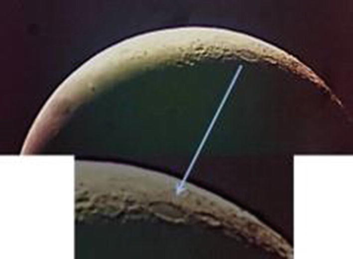
Lunar Eclipse on January 31, 2018
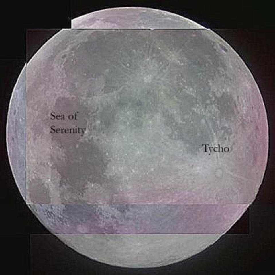
Full Moon on March 1, 2018
The next photo is of a full moon that occurred on March 1, 2018 (See Figure 7-48). It is pieced together from individual sections, as the whole moon does not fit in the screen.
Using an image such as this, the astronomer can start finding and labeling craters and features on the moon they observe.

Full Moon on April 19, 2019, Southern Region
Example Images Taken with the Upgraded 4 1/2-Inch Reflector Telescope Astrophotography System
The photos in this section were taken with the 4 ½-inch reflector using the body mount method previously described. It was a 40-year-old reflector telescope! There are some blemishes on the mirror, but they don’t impact the image. The tripod and vernier controls still work well.
Making an Astronomical Video and Creating Enhanced Images

Saturn from 4 1/2-Inch Reflector, April 11, 2018
Enhanced Saturn Image from 4 1/2-Inch Reflector, April 25, 2018
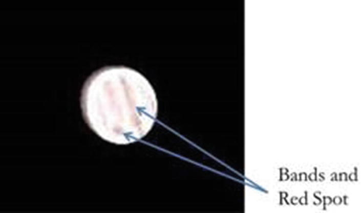
Enhanced Jupiter Image from 4 1/2-Inch Reflector, May 4, 2018
Figure 7-50 is unenhanced image and 7-51 is after enhancement.
Figures 7-51 and 7-52 are enhanced images using the techniques outlined in this section.
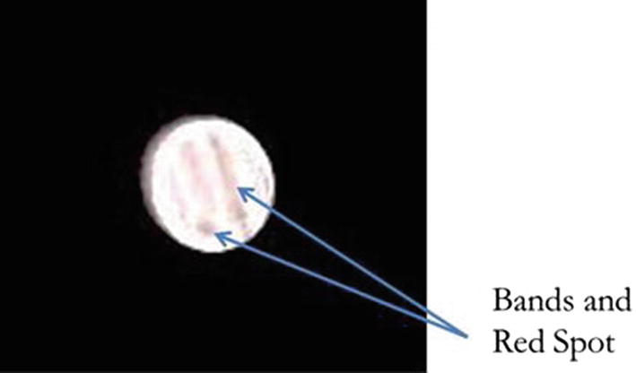
Figure 7-52 is the enhanced image taken with the 4 1/2-inch reflector showing the red spot and bands of Jupiter. This was the first time using this telescope the authors had seen the red spot and it was because of the enhancement techniques!
Raspberry Pi Code PI_SN004_Astrophotograhy_Video Capture
Image Creation and Enhancement from a Video
Converting the file to a normal video:
To open the “.h264” files that the Raspberry Pi creates in Windows
Install VLC player.
Open VLC player.
Drag the file onto the VLC player app.
Note: You don’t need to do this section; this is just to watch your video without doing any conversion.
To prepare the file to convert:
Open VLC player.
Click Media ➤ Convert/Save.
Click Add. Open the h264 file you saved that you want to convert.
Then select the Convert/Save button at the bottom right.
Select the destination toward the bottom of the next window. It will allow you to change file types if necessary. “.mp4” files seem to work great.
Once the file is converted to “.mp4”, you want to use PIPP to align the video where the planet is always in the middle:
Open PIPP.
Drag the “.mp4” video into the file window.
Check the planetary radio button at the bottom of the window.
Click Processing on the menu at the top and then start processing.
Once it is done, it will create a PIPP file folder in whatever directory your original “.mp4” video was in. The new video in the PIPP folder will have the planet aligned in the middle and will have an .avi format.
Registax is the tool that will rip the images out of the video and stack them in order to enhance the image. The following steps are what the authors used to create some of the images in this book.
- 1.
Load the .avi file that was created using PIPP into Registax.
- 2.
To set the alignment points, it is best to step through the frames of the video and find a good image that has the features you want to use for alignment. Click each alignment point. Registax leaves a little circle for each alignment point.
- 3.
To do the alignment, click Align, and then the software goes through the video and tries to find key images that have the alignment points and then lines them up.
- 4.
This step is a bit of trial and error; this process is called limit, and it tells Registax how to limit the number of frames used for the stacking process. The astronomer needs to select either the best percentage of frames to use or the actual number of best frames to use. Again this requires a bit of trial and error.
Then click Limit to reduce it down to the frames selected.
- 5.
Next, click Stack. Stacking images creates a single image with the focused parts of all the images.
- 6.
After it is finished stacking the images, click the Wavelet tab and use the slider bars to adjust the image to enhance it.
- 7.
Once the astronomer has a clean enhanced image they are happy with, they need to save it.
The following YouTube video is a very good overview of this process:
Recap of Example Images and Enhancement Techniques
This section shows a few images captured by the authors and provides a high-level overview of some of the tools and techniques used to enhance and create some spectacular images of the two largest planets in the Solar System.
Summary
This chapter provides the reader with some very exciting projects that expand on the use of the Arduino and Raspberry Pi to capture and record data regarding light and astronomical images in a way that would have been impossible just a few short years ago. The introduction of powerful devices like the light sensor and advanced digital cameras makes this possible. Add on the ability to utilize and share the data via computers, and again that approaches the original Star Trek tricorder!