
Chapter 10. IPSec VPN
10.0. Introduction
A virtual private network (VPN) provides a means for remote computers to securely communicate across a public wide area network (WAN), such as the Internet. VPN concepts and examples in this chapter will refer to the use of the IP Security (IPSec) protocol.
You can configure IPSec tunnels within ScreenOS to link two or more remote subnets or sites, as well as individual users or computers, to VPN concentration sites. The IPSec tunnel consists of a pair of unidirectional Security Associations (SAs) that specify the Security Parameters Index (SPI), the destination address of the peer, and which security protocol is employed, either the Authentication Header (AH) protocol, or the Encapsulating Security Payload (ESP).
Through the SA, the IPSec tunnel can provide the following security functions:
- Privacy
You can employ a variety of standardized encryption algorithms within IPSec. ScreenOS supports Data Encryption Standard (DES), Triple DES (3DES), and Advanced Encryption Standard (AES) encryption options.
- Integrity
Data authentication is performed by either the Message Digest 5 (MD5) or Secure Hash Algorithm-1 (SHA-1) hashing algorithm.
- Sender authentication
Sender authentication is provided through the use of Internet Key Exchange (IKE) IDs and preshared keys and, if using certificate-based authentication, can provide nonrepudiation of data origin.
Encryption algorithms depend on keying material to seed the process and provide the ability to recover clear text from the encrypted form. ScreenOS provides two methods for keying the IPSec tunnels:
Manual key
Auto-key IKE with preshared key or certificate
The primary focus of this chapter is site-to-site VPN configuration. We will present various scenarios covering policy-based tunneling as well as route-based and dynamic route-based designs. VPN for individual user connectivity is being solved in a much more elegant fashion with SSL-based products, reducing the need for IPSec in pure Remote-Access Server (RAS) solutions. However, Recipe 10.1 uses the NetScreen Remote IPSec client software for those who may need to deploy it.
IPSec Tutorial
The IPSec suite of protocols consists of two modes—transport and tunnel—and two main protocols: AH and ESP.
Modes
When both ends of the IPSec tunnel are hosts, you can use either the transport or the tunnel mode. When one or both ends of the tunnel are a ScreenOS device or a router, you must use tunnel mode. ScreenOS devices always operate in tunnel mode for IPSec and transport mode for Layer 2 Tunneling Protocol (L2TP)-over-IPSec.
- Transport mode
The IP packet is not encapsulated into another IP datagram. Also, the original IP headers are not included in the encryption process. With AH, the entire packet is authenticated; with ESP, the entire packet is authenticated, but only the payload of the packet is encrypted. The original IP headers are left in the clear, as shown in Figure 10-1.
- Tunnel mode
In tunnel mode, the entire original IP packet is encapsulated and a new IP header is added. With AH, the entire new packet is authenticated; with ESP, the original headers are included in the encrypted portion of the packet and the authentication does not include the new IP header area of the packet, as shown in Figure 10-2.


Protocols
Two main protocols are used within IPSec:
- AH
This security protocol authenticates the source of the IP packet as well as ensures the integrity of the packet’s contents. That is, the content has not changed since the source computer sent it.
- ESP
This security protocol is used to encrypt the contents of the entire IP packet as well as to authenticate the source and verify the integrity of the contents.
The AH protocol provides a means to authenticate the origin of a packet and verify that the content has not changed in transit. You can process each packet with a security function, whereby a hash-based message authentication code (HMAC) is added to the IPSec header. Two algorithms for providing authentication and integrity checking functions are available within ScreenOS:
- MD5
This algorithm produces a 128-bit hash (also called a digital signature or message digest) from a message of arbitrary length and a 16-byte key. The resulting hash is used, like a fingerprint of the input, to verify content and source authenticity and integrity.
- SHA-1
This algorithm produces a 160-bit hash from a message of arbitrary length and a 20-byte key. It is generally regarded as more secure than MD5 because of the larger hashes it produces. Because the computational processing is done in the ASIC, the performance cost is negligible.
ESP offers the authenticity and integrity checking that AH offers, as well as encryption for providing privacy for the data in transit. ESP in tunnel mode encapsulates the entire IP packet (header and payload) and then appends a new IP header to the now-encrypted packet. This new IP header contains the destination address needed to route the protected data through the network.
With ESP, you can encrypt and authenticate, encrypt only, or authenticate only. For authentication, you can use either MD5 or SHA-1 algorithms.
For encryption, you can choose one of the following encryption algorithms:
- DES
This is a cryptographic block algorithm with a 56-bit key.
- 3DES
This is a more powerful version of DES, in which the original DES algorithm is applied in three rounds, using a 168-bit key. DES provides a significant performance savings, but is considered unacceptable for many classified or sensitive material transfers.
- AES
This is an emerging encryption standard which, when adopted by Internet infrastructures worldwide, will offer greater interoperability with other network security devices. ScreenOS supports AES with 128-bit, 192-bit, and 256-bit keys.
Security Associations
A Security Association (SA) is a unidirectional agreement between the VPN participants regarding the methods and parameters to use in securing a communication channel. Full bidirectional communication requires at least two SAs, one for each direction.
An SA groups together the following components for securing communications:
Security algorithms and keys
Protocol mode (transport or tunnel)
Key-management method (manual key or auto-key IKE)
SA lifetime
For outbound VPN traffic, the policy or route invokes the SA associated with the VPN tunnel. For inbound traffic, the security device looks up the SA by using the following triplet:
Destination IP
Security protocol (AH or ESP)
SPI value
IKE and IPSec packets
An IPSec VPN tunnel consists of two major elements:
- Tunnel setup
The peers first establish SAs, which define the parameters for securing traffic between them. The admins at each end can define the SAs manually, or the SAs can be defined dynamically through IKE Phase-1 and Phase-2 negotiations. Phase 1 can occur in either Main mode or Aggressive mode. Phase 2 always occurs in Quick mode.
- Applied security
IPSec protects traffic sent between the two endpoints by using the security parameters defined in the SAs that the peers agreed to during tunnel setup. This could be statically defined or negotiated with IKE. The endpoints use AH or ESP for applying security functions to tunneled traffic.
Using IPSec in ScreenOS
ScreenOS provides a feature-rich implementation of IPSec. In fact, ICSA Labs uses ScreenOS to test other vendors for interoperability with this protocol. One primary reason for this is the IPSec debugging capability. Another reason is the adherence to the IPSec standards in ScreenOS.
Large VPNs have been built with ScreenOS. The fast tunnel establishment rate and stateful failover capabilities within a NetScreen Redundancy Protocol (NSRP) cluster have proven this to be a reliable and effective platform for creating large and sophisticated virtual private WANs (VPWANs).
ScreenOS provides two approaches to VPN networking:
Route-based versus policy-based tunneling
ScreenOS provides two mechanisms for deciding when to encrypt data and process the connection via IPSec. These mechanisms are referred to as policy-based tunneling and route-based tunneling. You configure the Phase-1 IKE gateway and the Phase-2 SA in the same way for either policy-based or route-based VPNs. The difference is whether the VPN is used in a policy with a tunnel action or whether the VPN is bound to a tunnel interface.
With policy-based VPNs, the stateful inspection engine matches the flow to a policy with a tunnel action, and subsequently encrypts the packet and processes the flow across the appropriate SA.
Route-based VPN technology takes a fundamentally different approach. VPNs are bound to logical tunnel interfaces which act much like any other interface on the security device. Once the tunnel interface is created and the VPN is bound to it, you simply use the route table to direct traffic to the interface. Traffic routed to a tunnel interface is processed by the appropriate SA. Because a route lookup occurs prior to stateful inspection, you are using the route table to decide when to encrypt a packet instead of the stateful inspection engine.
VPNs have become very popular as a cost-saving alternative to dedicated leased lines. Organizations require the same type of routed connectivity they had with their frame relay networks. For this reason, NetScreen developed route-based VPN technology early in the ScreenOS life cycle.
With policy-based VPNs, you are matching a rule within the firewall policy to have the flow processed via an IPSec SA. ScreenOS operates in a “first match wins” mode when performing stateful inspection. Therefore, consider this: your first rule in the policy is a tunnel action across a VPN to data center 1. This is your primary route to all corporate resources. But you want a backup path to the resources via data center 2, so you create a second tunnel and your second rule is now for this data center 2 tunnel. The problem is that a flow that matches rule #1 will never hit rule #2 and therefore will never be tunneled via data center 2. This posed a serious issue for designing robust VPNs.
The initial approach to solving this issue was the use of VPN groups. With this configuration, multiple tunnels were placed in a group, and this group was used in the policy statement instead of a single tunnel. This configuration allows the administrator to choose the preferred tunnel. In addition, a new function called the VPN monitor was created to check the health of the tunnel by sending Internet Control Message Protocol (ICMP) pings across the encrypted SA. If the preferred tunnel failed, traffic would be processed across the next available tunnel. VPN groups are still available in ScreenOS today, but are rarely, if ever, used.
Even with VPN groups, limitations existed. The need to build highly resilient, dynamically routed WANs using IPSec was prevalent. So, route-based VPNs were born. Though policy-based VPN is still used, primarily for interoperability with other vendors, route-based VPN has become the dominant method for creating VPN connectivity between ScreenOS devices.
Tunnel interfaces and VPN routing
Route-based VPNs use tunnel interfaces within ScreenOS. A tunnel interface is a logical interface created and used like other interfaces on the security device. IP addresses are assigned to these interfaces, or they can be used as unnumbered interfaces and can borrow the IP address from another interface, as most routers can do.
Tunnel interfaces are placed into security zones. With this configuration, you can inspect traffic traversing the VPN with simple zone-based firewall rules, with no need for the “tunnel” action to be used for this traffic. It is a standard practice to place the tunnel interfaces into a “VPN” security zone and to use firewall rules to permit certain traffic from the VPN zone to the other security zones configured on the system.
You use the following commands to create an unnumbered interface in the VPN zone:
S1-Denton->set interface tun.1 zone vpnS1-Denton->set interface tun.1 ip unnumbered interface eth0/0
Once the interfaces are created, the route table can reference them as a next hop for IP routing purposes. Where tunnel interfaces differ from other interfaces is the ability to bind Phase-2 VPN definitions to them. You can bind one or many SAs to a tunnel interface, allowing the interface to operate in point-to-point or point-to-multipoint mode.
When a packet enters the security device, the IP headers are parsed and a route lookup will be performed to determine the egress interface. If a route is present that directs the packet to a tunnel interface as a next hop, a VPN that is bound to the interface will process the packet. The route that directs traffic to a tunnel interface can be in the form of a static route, a dynamically learned route, or even a policy-based route.
Here is an example of a static route referencing a tunnel interface as a next-hop interface:
S1-Denton-> set route 10.11.12.0/24 interface tun.1You also can use dynamic routing for a route-based VPN. This is referred to as a dynamic route-based VPN. ScreenOS provides support for multiple Virtual Routers (VRs) as well as the RIPv2, Open Shortest Path First (OSPF), and Border Gateway Protocol (BGP) routing protocols. You can apply these features to route-based VPNs, offering highly resilient implementations. Please see Chapter 4 for information on routing within ScreenOS.
As mentioned, you can bind multiple VPNs to a tunnel interface. When the interface is used in a point-to-multipoint manner, a second routing table is required to ensure that the appropriate SA processes the packet. This second routing table is called the Next Hop Tunnel Binding (NHTB) table.
NHTB
NHTB is used when a tunnel interface has multiple VPN SAs bound to it. Each tunnel interface maintains its own NHTB table. A route in the system will direct traffic to the tunnel interface with a next-hop gateway address, and the NHTB table will map a gateway address to a specific VPN tunnel. You can use NHTB for a variety of needs:
- To overcome limits in resources supported on a security device
For instance, say a device supports 20,000 VPN tunnels but only 4,096 tunnel interfaces. Here, you can bind five VPNs to each tunnel and theoretically achieve the maximum tunnel count with a route-based approach.
- To support multiple Phase-2 SAs to the same gateway
When interoperating with some vendors, you must create individual Phase-2 definitions that match the proxy IDs to accommodate noncontiguous subnets. You can use NHTB to place the flows into the appropriate SA.
- To scale dynamic routing protocols
When you use point-to-multipoint interfaces, fewer interfaces are participating in the routing protocol(s), and thus fewer resources are required.
As an example of NHTB configuration, consider that destination address 4.3.2.1/32 is at the other end of a VPN tunnel named corp, which is bound to tun.1. The following route is created:
S1-Denton-> set route 4.3.2.1/32 interface tun.1 gateway 1.2.3.4The gateway address used here has no relevance to the network addressing used in the real network. It simply needs to be unique. A common practice is to use the IKE peer address. However, you can simply make up an address. Only the NHTB tables use it, as follows:
S1-Denton-> set interf tun.1 nhtb 1.2.3.4 vpn corpThis configuration routes the traffic into the appropriate tunnel. When traffic is received on interface tun.1, the system will consult the NHTB table and look for gateway 1.2.3.4. That gateway is mapped to the corptunnel on that interface. The same security device could also have the following configuration:
S1-Denton->set route 5.6.7.8/32 interface tun.1 gateway 1.2.3.5S1-Denton->set interf tun.1 nhtb 1.2.3.5 vpn datactr1
Tip
The preceding example represents statically configuring the NHTB mappings for tunneled traffic. NHTB configuration is automatically created between ScreenOS devices, and is necessary only for mixing route-based and policy-based configurations or for interoperability with non-ScreenOS devices.
Recipe 10.5 provides examples of statically configured NHTB mapping, though it would be acceptable to allow ScreenOS to create the configuration automatically.
Creating VPN Tunnels
You can create a VPN tunnel by following three main steps:
Create the Phase-1 gateway and associated parameters.
Create the Phase-2 VPN definition and associated parameters.
Bind the VPN to a policy or tunnel interface.
Configuring an IKE gateway
When a clear-text packet arrives at the security device that requires tunneling and no active SA exists for that tunnel, the security device begins IKE negotiations (and drops the packet). The source and destination addresses in the IP packet header are those of the local and remote IKE gateways, respectively. In the IP packet payload, a User Datagram Protocol (UDP) segment encapsulates an Internet Security Association and Key Management Protocol (ISAKMP), or IKE, packet. The format for IKE packets is the same for Phase 1 and Phase 2.
Tip
When the initial IP packet is dropped, the source host resends it. Typically, by the time the second packet reaches the security device, IKE negotiations are complete and the security device protects it—and all subsequent packets in the session—with IPSec before forwarding it. See the “VPN monitor” section later in this chapter for information on how to avoid this dropped data packet.
Main and Aggressive modes
Phase 1 can take place in either Main or Aggressive mode:
- Main mode
The initiator and recipient send three two-way exchanges (six messages total) to accomplish the following services:
- First exchange (messages 1 and 2)
Propose and accept the encryption and authentication algorithms.
- Second exchange (messages 3 and 4)
Execute a Diffie-Hellman exchange, and the initiator and recipient each provide a pseudorandom number.
- Third exchange (messages 5 and 6)
Send and verify their identities. The encryption algorithm established in the first two exchanges protects the information transmitted in the third exchange of messages. Thus, the participants’ identities are not transmitted in the clear.
- Aggressive mode
The initiator and recipient accomplish the same objectives, but only in two exchanges, with a total of three messages:
- First message
The initiator proposes the SA, initiates a Diffie-Hellman exchange, and sends a pseudorandom number and its IKE identity.
- Second message
The recipient accepts the SA, authenticates the initiator, and sends a pseudorandom number, its IKE identity, and, if using certificates, the recipient’s certificate.
- Third message
The initiator authenticates the recipient, confirms the exchange, and, if using certificates, sends the initiator’s certificate. Because the participants’ identities are exchanged in the clear (in the first two messages) Aggressive mode does not provide identity protection.
Tip
When a dial-up VPN user negotiates an auto-key IKE tunnel with a preshared key, you must use Aggressive mode. Note also that a dial-up VPN user can use an email address, a fully qualified domain name (FQDN), or an IP address as its IKE ID. A dynamic peer can use either an email address or an FQDN, but not an IP address.
Diffie-Hellman exchange
A Diffie-Hellman (DH) exchange allows the participants to produce a shared secret value. The strength of the technique is that it allows the participants to create the secret value over an unsecured medium without passing the secret value through the wire. There are five DH groups; ScreenOS supports Groups 1, 2, and 5. The size of the prime modulus used in each group’s calculation differs as follows:
- DH Group 1
768-bit modulus
- DH Group 2
1024-bit modulus
- DH Group 5
1536-bit modulus
The larger the modulus, the more secure the resulting key is considered to be. Also, the larger the modulus, the longer it takes ScreenOS to generate. Because the different groups use a different size modulus, both ends of the tunnel must use the same group.
Configuring a Main mode gateway
Auto-key IKE Phase-1 gateways using Main mode negotiations can use a variety of IKE ID types, with the most common being the IP address of the outgoing interface. To start the configuration, create an IKE gateway and name it:
S1-Denton-> set ike gateway "dallas"Here is the start of an IKE gateway command. A gateway named "dallas" is going to need some additional configuration. Next, specify the remote IKE gateway address in which to negotiate a tunnel:
S1-Denton-> set ike gateway "dallas" address 10.11.12.1 mainThis is the beginning of a Main mode Phase-1 configuration for a gateway named "dallas" which will connect to IP address 10.11.12.1. Next, the specified outgoing interface will be defined as well as choosing to use a preshared key and the value of that key:
	S1-Denton-> set ike gateway "dallas" address 10.11.12.1 main outgoing-
	interface eth0/0 preshare juniper123
The Phase-1 Main mode configuration command is almost complete. The last part of the configuration is to choose a Phase-1 proposal to offer or accept during the negotiation. You can configure up to four proposals for each gateway configuration and they will be offered or accepted in the order in which they appear in the configuration. For convenience purposes, ScreenOS also offers three predefined security levels, each having multiple proposals:
	S1-Denton-> set ike gateway "dallas" address 10.11.12.1 main outgoing-
	interface eth0/0 preshare juniper123 sec-level ?
	basic                basic level settings
	compatible           most popular settings
	standard             recommended settings
The set ike gateway command is probably the longest single command you will ever enter in ScreenOS, so don’t despair, it gets better. The following is a complete IKE Phase-1 gateway configuration command:
	S1-Denton-> set ike gateway "dallas" address 10.11.12.1 main outgoing-
	interface eth0/0 preshare juniper123 sec-level standard
The predefined security levels are as follows:
	S1-Denton-> get ike p1-sec-level

	IKE Phase-1 Standard Level:
	Id Name               Auth     Grp ESP-e  ESP-a Lifetime
	-- ------------------ -------- --- ------ ----- ----------
	 5 pre-g2-3des-sha    Preshare  2  3DES   SHA-1      28800
	 7 pre-g2-aes128-sha  Preshare  2  AES128 SHA-1      28800

	IKE Phase-1 Compatible Level:
	Id Name               Auth     Grp ESP-e  ESP-a Lifetime
	-- ------------------ -------- --- ------ ----- ----------
	 5 pre-g2-3des-sha    Preshare  2  3DES   SHA-1      28800
	 4 pre-g2-3des-md5    Preshare  2  3DES   MD5        28800
	 3 pre-g2-des-sha     Preshare  2  DES    SHA-1      28800
	 2 pre-g2-des-md5     Preshare  2  DES    MD5        28800

	IKE Phase-1 basic Level:
	Id Name               Auth     Grp ESP-e  ESP-a Lifetime
	-- ------------------ -------- --- ------ ----- ----------
	 1 pre-g1-des-sha     Preshare  1  DES    SHA-1      28800
	 0 pre-g1-des-md5     Preshare  1  DES    MD5        28800
	S1-Denton->
You also can create custom proposals as needed:
	S1-Denton-> set ike p1-proposal custom1 pre group5 esp aes256 sha
	seconds 12800
	S1-Denton-> get ike p1-proposal custom1
	Id Name               Auth     Grp ESP-e  ESP-a Lifetime
	-- ------------------ -------- --- ------ ----- ----------
	20 custom1            Preshare  5  AES256 SHA-1      12800
You can express the Phase-1 lifetime in seconds, minutes, hours, or days, but it is always displayed in seconds:
S1-Denton->set ike p1-proposal custom1 pre group5 esp aes256 sha days 7S1-Denton->get ike p1-proposal custom1Id Name Auth Grp ESP-e ESP-a Lifetime -- ------------------ -------- --- ------ ----- ---------- 20 custom1 Preshare 5 AES256 SHA-1 604800
Configuring an Aggressive mode gateway
IKE Aggressive mode is typically used between devices where one end of the tunnel is assigned a dynamic IP (DIP) address. One end of the tunnel must always have either a static IP address or an FQDN. When one IKE peer is dynamic, that peer cannot use the IPv4 address as the IKE ID and must use another IKE ID type, such as an email address or FQDN.
The configuration starts the same as in Main mode, where you create an IKE gateway and name it:
S1-Denton-> set ike gateway "corp"If you’re configuring the dynamic peer, the configuration continues with the IP address of the peer gateway and choosing Aggressive mode:
S1-Denton-> set ike gateway "corp" address 10.140.0.3 AggressiveNext, you would configure the IKE ID the dynamic peer will present when negotiating the tunnel:
	S1-Denton-> set ike gateway "corp" address 10.140.0.3 Aggr local-id s1_
	[email protected]
The rest of the configuration will continue the same as in the Main mode example explained previously:
	S1-Denton-> set ike gateway "corp" address 10.140.0.3 Aggr local-id s1_
	[email protected]" outgoing-interface "ethernet0/0" preshare
	juniper123 sec-level standard
The corresponding Phase-1 configuration on the static peer would look as follows:
	set ike gateway denton dynamic [email protected] aggressive
	outgoing-interface eth0/3 preshare juniper123 sec-level standard
In this command, instead of specifying the IKE peer’s address, we use the dynamic keyword to signify that the peer has a DIP address immediately followed by the IKE ID expected from this remote IKE gateway. This is followed by choosing the appropriate outgoing interface and matching the preshared key and Phase-1 proposal or security level.
Configuring a Phase-2 VPN
After the participants have established a secure and authenticated channel, they proceed through Phase 2, in which they negotiate the SAs to secure the data to be transmitted through the IPSec tunnel. As in the process for Phase 1, the participants exchange proposals to determine which security parameters to employ in the SA. A Phase-2 proposal also includes a security protocol—either ESP or AH—and selected encryption and authentication algorithms.
The proposal can also specify a DH group, if Perfect Forward Secrecy (PFS) is desired. Regardless of the mode used in Phase 1, Phase 2 always operates in Quick mode and involves the exchange of three messages. Juniper Networks security devices support up to four proposals for Phase-2 negotiations, allowing you to define how restrictive a range of tunnel parameters you will accept. ScreenOS also provides a replay protection feature. Use of this feature does not require negotiation because packets are always sent with sequence numbers. You simply have the option of checking or not checking the sequence numbers.
The following command creates a Phase-2 VPN, links the definition to a configured IKE gateway, and specifies the security level to use for the offered/accepted Phase-2 proposals:
S1-Denton-> set vpn corp_vpn gateway corp sec-level standardAlternatively, you could use a predefined or custom proposal:
S1-Denton-> set vpn corp_vpn gate corp proposal g2-esp-aes128-shaThe predefined Phase-2 proposals that ScreenOS provides are as follows:
	S1-Denton-> get ike p2-proposal
	Id Name                 Grp Protocol Enc_alg Auth_alg Lifetime Lifesize
	-- -------------------- -- -------- ------- -------- -------     ------
	 0  nopfs-esp-des-md5    0   ESP     DES     MD5         3600       0
	 1  nopfs-esp-des-sha    0   ESP     DES     SHA-1       3600       0
	 2  g2-esp-des-md5       2   ESP     DES     MD5         3600       0
	 3  g2-esp-des-sha       2   ESP     DES     SHA-1       3600       0
	 4  nopfs-esp-3des-md5   0   ESP     3DES    MD5         3600       0
	 5  nopfs-esp-aes128-md5 0   ESP     AES128  MD5         3600       0
	 6  g2-esp-3des-md5      2   ESP     3DES    MD5         3600       0
	 7  g2-esp-aes128-md5    2   ESP     AES128  MD5         3600       0
	 8  nopfs-esp-3des-sha   0   ESP     3DES    SHA-1       3600       0
	 9  g2-esp-3des-sha      2   ESP     3DES    SHA-1       3600       0
	10  nopfs-esp-aes128-sha 0   ESP     AES128  SHA-1       3600       0
	11  g2-esp-aes128-sha    2   ESP     AES128  SHA-1       3600       0
	   Total Phase 2 proposals:   12
	S1-Denton->
As with the Phase-1 configuration, ScreenOS also offers three predefined security levels to choose from for convenience. Each security level contains multiple proposals, and will be offered or accepted in the order in which it appears:
	S1-Denton-> get ike p2-sec-level

	IKE Phase-2 Standard Level:
	Id Name              Grp Protocol Enc_alg Auth_alg Lifetime Lifesize
	-- ----------------- --- -------- ------- -------- ------- ---------
	 9 g2-esp-3des-sha     2 ESP      3DES    SHA-1       3600       0
	11 g2-esp-aes128-sha   2 ESP      AES128  SHA-1       3600       0

	IKE Phase-2 Compatible Level:
	Id Name              Grp Protocol Enc_alg Auth_alg Lifetime Lifesize
	-- ----------------- -- -------- ------- -------- ------ ----------
	 8 nopfs-esp-3des-sha  0 ESP      3DES    SHA-1       3600       0
	 4 nopfs-esp-3des-md5  0 ESP      3DES    MD5         3600       0
	 1 nopfs-esp-des-sha   0 ESP      DES     SHA-1       3600       0
	 0 nopfs-esp-des-md5   0 ESP      DES     MD5         3600       0

	IKE Phase-2 basic Level:
	Id Name              Grp Protocol Enc_alg Auth_alg Lifetime Lifesize
	-- ----------------- --- -------- ------- -------- ------ ----------
	 1 nopfs-esp-des-sha   0 ESP      DES     SHA-1       3600       0
	 0 nopfs-esp-des-md5   0 ESP      DES     MD5         3600       0
	S1-Denton->
You can also define custom Phase-2 proposals. In Phase 2, the peers also exchange proxy IDs. A proxy ID is a three-part tuple consisting of a local IP address—remote IP address and service. The proxy ID for both peers must match, which means that the service specified in the proxy ID for both peers must be the same, and the local IP address specified for one peer must be the same as the remote IP address specified for the other peer. For tunnels between ScreenOS devices, you usually can skip this in the configuration and let the default parameters prevail. However, when you need to match the proxy ID for interoperability and you’re mixing route-based and policy-based VPNs, you can use the following command to configure the local and remote proxy IDs and service tuple:
	S1-Denton-> set vpn corp_vpn proxy-id local 10.1.1.0/24 remote
	10.2.1.0/24 any
The preceding command uses the any keyword for the service definition to allow any service to match the proxy ID.
Perfect Forward Secrecy. PFS is a method for deriving Phase-2 keys independent from and unrelated to the preceding keys. Alternatively, the Phase-1 proposal creates the key (the SKEYID_d key) from which all Phase-2 keys are derived. The SKEYID_d key can generate Phase-2 keys with a minimum of CPU processing. Unfortunately, if an unauthorized party gains access to the SKEYID_d key, all of your encryption keys are compromised. PFS addresses this security risk by forcing a new DH key exchange to occur for each Phase-2 tunnel. Using PFS is thus more secure, although the rekeying procedure in Phase 2 might take slightly longer with PFS enabled.
Replay protection. A replay attack occurs when somebody intercepts a series of packets and uses them later either to flood the system—causing a Denial of Service (DoS)—or to gain entry to the trusted network. The replay protection feature enables security devices to check every IPSec packet to see whether it has been received previously. If packets arrive outside a specified sequence range, the security device rejects them.
VPN monitor
The VPN monitor is a simple mechanism used for determining the health and latency of a given VPN tunnel. ICMP pings are sent across the encrypted SA every n seconds as determined by the “interval” setting. A threshold is also set which determines how many pings can be lost before declaring the tunnel as down. The following shows the default settings for the VPN monitor:
	S1-Denton-> get vpnmon
	Vpn monitor interval : 10(seconds)
	Vpn monitor threshold: 10
These default settings would require 100 seconds before the tunnel was declared as down. A ping will be sent every 10 seconds, and 10 pings must fail before the tunnel is considered down. You can set the interval and threshold to meet your needs:
S1-Denton->set vpnmon interval 3S1-Denton->set vpnmon threshold 3
These settings would declare the tunnel down after nine seconds of failure. The setting is global, so you cannot have different settings for different tunnels.
Besides simply providing notification that a tunnel is down, the VPN monitor has other uses. For instance, it also measures the latency of the ICMP responses for providing latency statistics. But probably the most useful function of the VPN monitor is the ability to alter the route table based on a tunnel failure. When used with route-based VPN, the VPN monitor can mark routes associated with VPN tunnels as inactive when a tunnel is declared as down, allowing the next best route to be selected.
By default, the VPN monitor will use the local and remote IKE peer addresses for the ping packet. ScreenOS is aware of the VPN monitor and will accept and respond to the ping.
Normally, the following command is all that is required to enable the VPN monitor:
S1-Denton-> set vpn corp monitor
However, other vendors do not understand the VPN monitor. So, when using the VPN monitor with other vendors, you must use an additional configuration and specify a source interface and a destination IP address that will comply with the proxy ID configured on the tunnel. An example configuration is as follows:
	S1-Denton-> set vpn corp monitor source-interface eth1 destination-ip
4.3.2.1optimized. Another option exists in the VPN monitor, called optimized. With this option enabled, ScreenOS will look into the tunnel and see whether there is active traffic on the SA for every interval configured. If there is active traffic, ScreenOS will not send the ICMP ping and will consider the tunnel active. If no active data is sensed, ScreenOS will send the monitor ping. You can use the optimized option in large networks to reduce unnecessary data transport. However, if you are relying on VPN latency counters, you should not use optimized, as counters are provided only for the ICMP monitor pings.
S1-Denton-> set vpn corp monitor optimizedrekey. If you enable the rekey option, the security device starts to send ICMP echo requests immediately upon completion of the tunnel configuration, and continues to send them indefinitely. The echo requests trigger an attempt to initiate IKE negotiations to establish a VPN tunnel until the state of VPN monitoring for the tunnel is up. The security device then uses the pings for VPN monitoring purposes. If the state of VPN monitoring for the tunnel changes from up to down, the security device deactivates its Phase-2 SA for that peer. The security device continues to send echo requests to its peer at defined intervals, triggering attempts to reinitiate IKE Phase-2 negotiations—and Phase-1 negotiations, if necessary—until it succeeds. At that point, the security device reactivates the Phase-2 SA, generates a new key, and reestablishes the tunnel. A message appears in the event log stating that a successful rekey operation has occurred:
S1-Denton-> set vpn corp monitor optimized rekeyYou can view the progress of the VPN monitor with debug. Several options exist, but here is a basic method for checking the VPN monitor:
S1-Denton->debug sa-mon allS1-Denton->get db strvpn monitor pkt is received: cookie = 3, result = 3 ## 2007-09-23 11:47:44 : vpnmon_down_action 3 sa index(3) changed to down sa index(3) send count = 396386, avail = 307684, tunnel_info = 4000000e
Here, we see that a tunnel status has changed to down, and we have sent 396,386 pings, but have received only 307,684 responses.
The route table might look like this now:
	IPv4 Dest-Routes for <trust-vr> (69 entries)
	---------------------------------------------------------------------
	   ID       IP-Prefix  Interface     Gateway    P Pref   Mtr     Vsys
	---------------------------------------------------------------------
	*55288       0.0.0.0/0     eth0/0    10.0.1.3   E2  200     1    Root
	 59269      4.3.2.1/32      tun.1     1.2.3.4    S   20     1    Root
	     6    10.15.0.0/16      tun.1     0.0.0.0    S   20    10    Root
	*55319     10.0.0.1/32     eth0/0  10.0.1.254    O   60     3    Root
	*59235     10.1.5.0/30     eth0/0  10.0.1.254    O   60     4    Root
	*59236    10.31.0.3/32     eth0/0  10.0.1.254    O   60     4    Root
	S1-Denton->
The two static routes associated with tunnel.1 are inactive (there is no asterisk signifying an active route). With no active route to those destinations, traffic will be routed to the next best route, which in this case is the default route, unencrypted out to the Internet. This could be bad, and it is at least a bad practice. To remedy this situation, you should use a static route with a higher metric to direct traffic to the null interface (blackhole), like so:
	S1-Denton-> get route | i 10.15.0.0/16
	*59270       10.15.0.0/16     null   0.0.0.0     S   20   100    Root
	    6        10.15.0.0/16    tun.1   0.0.0.0     S   20    10    Root
	    7        10.15.0.0/16    tun.2   0.0.0.0     S   20    50    Root
	S1-Denton->
In this example, the primary route via tun.1 and the backup route via tun.2 are both unavailable, so our blackhole route takes over.
Restoring the VPN connectivity to normal results in the following route table:
	S1-Denton-> get route | i 10.15.0.0/16
	59270       10.15.0.0/16      null   0.0.0.0     S   20   100    Root
	   *6       10.15.0.0/16     tun.1   0.0.0.0     S   20    10    Root
	    7       10.15.0.0/16     tun.2   0.0.0.0     S   20    50    Root
	S1-Denton->
Finishing the tunnel configuration
Now that both Phase-1 and Phase-2 configurations have been completed, the final step is to bind the Phase-2 VPN to either a policy or a tunnel interface.
For the route-based method, the VPN is bound to a tunnel interface and the appropriate routes are configured or dynamically exchanged between peers. Using static routes, the following commands would finish the VPN configuration, and would set up routing to subnet 10.11.12.0/24 via the VPN tunnel named corp:
S1-Denton->set vpn corp bind interface tun.1S1-Denton->set route 10.11.12.0/24 interface tun.1
For policy-based configuration, the commands would look as follows:
S1-Denton->set address vpn corp_subnet 10.11.12.0/24S1-Denton->set policy from trust to vpn any corp_subnet any tunnel vpn corp log
Many of the chapters in this book are relevant to VPN design. Specifically, those chapters on interfaces, objects and policies, and routing (Chapters Chapter 4, Chapter 7, and Chapter 19 to mention a few) will provide additional information to assist with designing and implementing a VPN solution. Check the index and table of contents for more specific VPN references.
10.1. Create a Simple User-to-Site VPN
Problem
You need to provide VPN connectivity between multiple roaming users and the headquarters location.
Solution
Use NetScreen-Remote software to establish a secure tunnel to the hub location for a group of remote users with local Xauth authentication. Because multiple users will need to access this VPN, a shared IKE ID with a preshared key approach will be used.
First, define your protected resources (address objects):
Corp-VPN-Hub-> set address trust mail1 10.140.10.10/32Now, set the IKE ID, users, and group configuration:
Corp-VPN-Hub->set user lab_users ike-id [email protected] share-limit 250Corp-VPN-Hub->set user-group dallab_users user lab_usersCorp-VPN-Hub->set user dude password letmeinCorp-VPN-Hub->set user dude type xauthCorp-VPN-Hub->set user mike password 12345678Corp-VPN-Hub->set user mike type xauth
Set the VPN Phase-1 and Phase-2 configurations:
Corp-VPN-Hub->set ike gateway lab_gateway dialup dallab_users aggressive outgoing-interface eth0/3 preshare juniper123 sec-level standard Shared IKE ID dial-up group configured. Please note XAUTH server must be turned on as well.Corp-VPN-Hub->set ike gateway lab_gateway xauthCorp-VPN-Hub->set vpn lab_vpn gateway lab_gateway sec-level standard
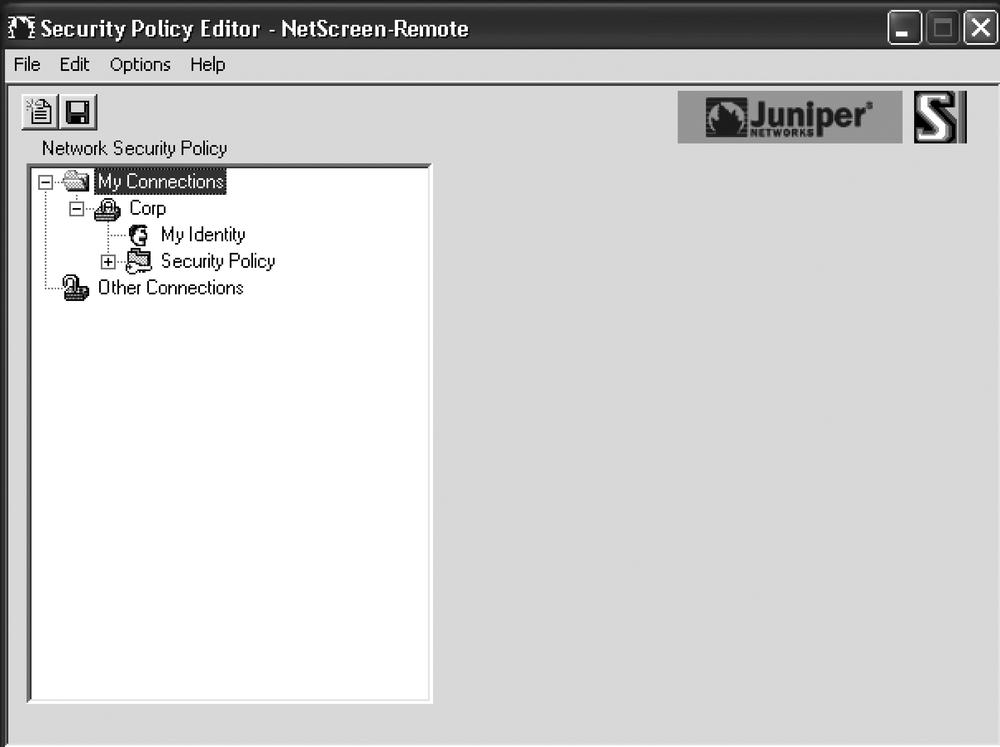
Create a new connection using the NetScreen-Remote setup (named “Corp” in this example), as shown in Figure 10-3.
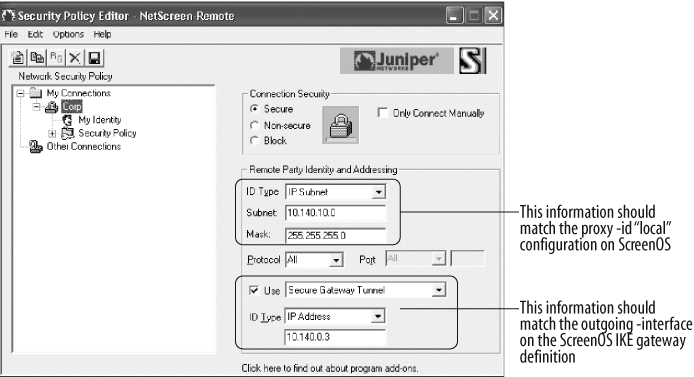
As shown in Figure 10-4, configure the remote identity information.

As shown in Figure 10-5, configure the local identity, select the Virtual Adapter as Preferred, and choose the interface of the local PC to use for this connection. Click the Pre-Shared Key button and enter the correct key.
As shown in Figure 10-6, choose Aggressive Mode, and enable PFS with DH Group 2 to match the “standard” proposal chosen in the ScreenOS configuration. We did not use replay protection in this example, but you could easily enable it on each end of the connection if desired.
As shown in Figure 10-7, configure the Phase-1 parameters in the client to match the “standard” proposal chosen on the hub site ScreenOS configuration. Ensure that Pre-Shared Key; Extended Authentication is chosen. This will prompt the user for the Xauth credentials.

And finally, as shown in Figure 10-8, configure the Phase-2 parameters to match the “standard” proposal chosen on the hub site ScreenOS configuration.
Discussion
Figure 10-9 depicts the scenario for this recipe and the ensuing discussion which details the VPN client software deployment.
ScreenOS configuration
Multiple traveling users with NetScreen-Remote VPN client software need to access the corporate site for mail and perhaps other applications. We used a policy-based approach here, but a route-based approach is also viable.
Because of the need to support multiple users, we chose to use a shared IKE ID and preshared key to simplify the VPN client software deployment. In this configuration, each remote user can have the same configuration in the NetScreen-Remote software. Because of this, we need some method to distinguish individual users. When configuring an IKE gateway definition on ScreenOS using a shared IKE ID, ScreenOS forces the use of Xauth and a reminder is displayed in the client to enable Xauth functionality.

You start the configuration by defining the resource the remote users will access. The address object mail1 is created with an IP address of 10.140.10.10/32:
Corp-VPN-Hub-> set address trust mail1 10.140.10.10/32
This object will be used in the policy configuration as a destination address.
Next, you configure the users, passwords, and shared IKE ID for Phase-1 establishment:
Corp-VPN-Hub->set user lab_users ike-id[email protected]share-limit 250Corp-VPN-Hub->set user-group dallab_users user lab_usersCorp-VPN-Hub->set user dude password letmeinCorp-VPN-Hub->set user dude type xauthCorp-VPN-Hub->set user mike password 12345678Corp-VPN-Hub->set user mike type xauth
In the preceding commands, the first line creates a user called lab_users, defines an IKE ID of [email protected], and defines the number of simultaneous connections supported by this IKE ID to be 250.
Next, you create a group named dallab_users and place the newly created user definition within the group. The reason for this step is that the IKE gateway definition to be completed later will accept only groups and not individual user definitions.

Then, you create two users with passwords and define each user as type Xauth.
Tip
This example uses a locally configured username and password pair for Xauth authentication. However, you could use an external authentication server for this function; that is, you could use your Active Directory users and credentials to authenticate these remote users to keep from having to define them locally. Please see Chapter 13 for more information on using external authentication servers.
Now, you can create the VPN Phase-1 and Phase-2 configuration on the hub site:
Corp-VPN-Hub->setet ike gateway lab_gateway dialup dallab_users aggressive outgoing-interface eth0/3 preshare juniper123 sec-level standard Shared IKE ID dial-up group configurated. Please note XAUTH server must be turned on as well.Corp-VPN-Hub->set ike gateway lab_gateway xauthCorp-VPN-Hub->set vpn lab_vpn gateway lab_gateway sec-level standard
First, you configure the IKE gateway definition by naming the gateway entry, configuring it to accept any IP address by using the dialup keyword, defining the user group dallab_users that is authorized to access the VPN, and finally choosing the appropriate outgoing interface, preshared key, and proposal. When configuring this Phase-1 gateway definition, ScreenOS warns you that Xauth must be enabled for this gateway due to the use of the shared IKE ID and preshared key. So, you enable it with the next line of the configuration.


The final step in configuring the hub device is to create a policy with a tunnel action:
Corp-VPN-Hub->set policy top from bb to trust "Dial-Up VPN" mail1 smtp tunnel vpn lab_vpn policy id = 3Corp-VPN-Hub->save
You want to make sure that your VPN policies are matched before other zone-based policies, so it is a best practice to insert the VPN policies at the top of the rule base. This example shows a rule created at the top that matches flows that originated on the bb zone from any IP address, are destined for the Trust zone and mail1 address, and utilize the Simple Mail Transfer Protocol (SMTP). This matched traffic will be tunneled within the lab_vpn VPN tunnel.
Now you can easily create additional rules to add additional applications or destination host addresses.
NetScreen-Remote configuration
Configuring NetScreen-Remote is fairly straightforward once you understand which screens relate to the ScreenOS configuration, as shown in Figure 10-10.
To start, configure the My Identity tab in the NetScreen-Remote client configuration, as shown in Figure 10-11.

As shown in Figure 10-12, enable Aggressive mode and PFS with DH Group 2 in the Security Policy tab.

Enter the Phase-1 proposal information in the following screen, as shown in Figure 10-13.

Lastly, complete the Phase-2 proposal configuration in the client software, as shown in Figure 10-14.

Troubleshooting client connectivity
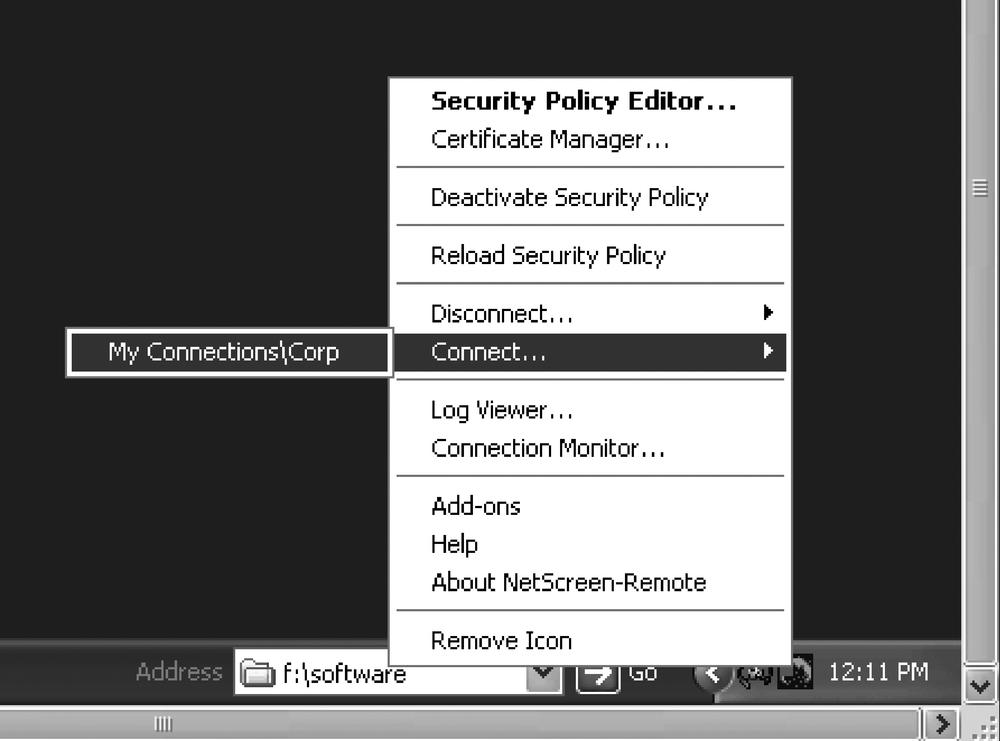
To test client connectivity, you can manually connect to the hub site from the VPN client software. Right-click the NetScreen-Remote icon in the taskbar and choose Connect, as shown in Figure 10-15.
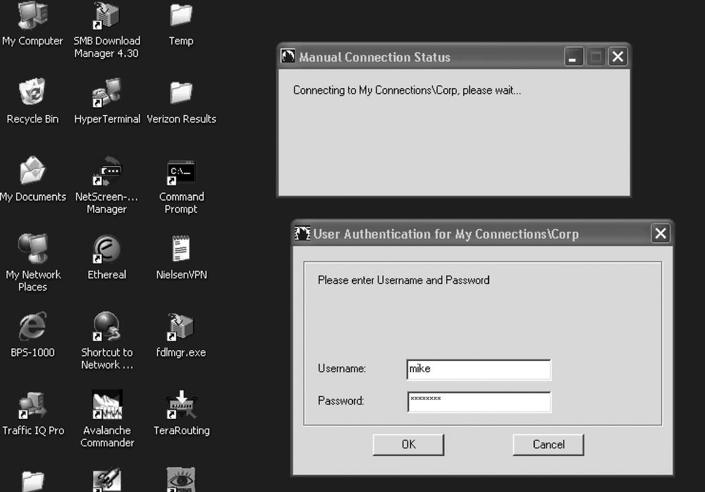
This should cause the NetScreen-Remote client to connect and you should quickly be prompted for the Xauth username and password, as shown in Figure 10-16.
If NetScreen-Remote is configured correctly, you should get a message stating that you are connected and the NetScreen-Remote icon in the taskbar should change to show a key icon.
A proper connection should also be recorded in the event log. You can view it with the following command.
	Corp-VPN-Hub-> get event type 536
	Date       Time     Module Level Type Description
	2007-09-09 12:39:36 system info 00536 IKE<10.20.10.75> Phase 2 msg ID
	                                <92cb95cc>:Completed negotiations
	                                with SPI <4958d748>, tunnel ID
	                                <32770>,and lifetime <3600>
	                                seconds/<0> KB.
	2007-09-09 12:39:36 system info 00536 IKE<10.20.10.75> Phase 2 msg-id
	                                <92cb95cc>: Completed for user
	                                <[email protected]>.
	2007-09-09 12:39:36 system info 00536 IKE<10.20.10.75> Phase 2 msg ID
	                                <92cb95cc>:Responded to the peer's
	                                first message from user
	                                <[email protected]>.
	2007-09-09 12:39:36 system info 00536 IKE<10.20.10.75>: XAuth login
	                                was passed for gateway <lab_gateway>,
	                                username <mike>, retry: 1, Client IP
	                                Addr<0.0.0.0>,IPPool name:< >,
	                                Session-Timeout:<0s>,Idle-Timeout:<0s>
	2007-09-09 12:37:59 system info 00536 IKE<10.20.10.75>:Received
	                                initial contact notification and
	                                removed Phase 1 SAs.
	2007-09-09 12:37:59 system info 00536 IKE<10.20.10.75>Phase 1:
	                                Completed Aggressive mode negotiations
	                                with a <28800>-second lifetime.
	2007-09-09 12:37:59 system info 00536 IKE<10.20.10.75> Phase 1:
	                                Completed for user
	                                <[email protected]>.
	2007-09-09 12:37:59 system info 00536 IKE<10.20.10.75>: Received
	                                initial contact notification and
	                                removed Phase 2 SAs.
	2007-09-09 12:37:59 system info 00536 IKE<10.20.10.75>: Received a
	                                notification message for DOI <1>
	                                <24578> <INITIAL-CONTACT>.
	2007-09-09 12:37:59 system info 00536 IKE<10.20.10.75>: Received a
	                                notification message for DOI <1>
	                                <24577> <REPLAY-STATUS>.
	2007-09-09 12:37:58 system info 00536 IKE<10.20.10.75> Phase 1:
	                                Responder starts AGGRESSIVE mode
	                                Responder
	Total entries matched = 11
	Corp-VPN-Hub->
The most common error in this configuration is a proposal or proxy ID mismatch. You can easily identify both by using debug ike commands:
Corp-VPN-Hub->debug ike basicCorp-VPN-Hub->clear dbCorp-VPN-Hub->get db str## 2007-09-09 12:48:23 : IKE<10.20.10.75> ****** Recv packet if <ethernet0/3> of vsys <Root> ****** ## 2007-09-09 12:48:23 : IKE<10.20.10.75 > Recv : [SA] [KE] [NONCE] [ID] [VID] ## 2007-09-09 12:48:23 : IKE<10.20.10.75> ****** Recv packet if <ethernet0/3> of vsys <Root> ****** ## 2007-09-09 12:48:23 : IKE<10.20.10.75 > Recv*: [HASH] [NATD] [NATD] [NOTIF] [NOTIF] ## 2007-09-09 12:48:23 : IKE<10.20.10.75> Phase 1: Completed for ip <10.20.10.75>, user<[email protected]> ## 2007-09-09 12:48:23 : IKE<10.20.10.75> Phase 1: Completed Aggressive mode negotiation with a <28800>-second lifetime.## 2007-09-09 12:48:30 : IKE<10.20.10.75> local address NOT matched. ## 2007-09-09 12:48:30 : IKE<10.20.10.75> local address NOT matched. ## 2007-09-09 12:48:30 : IKE<10.20.10.75> Proxy ID match: No policy exists for the proxy ID received ## 2007-09-09 12:48:30 : IKE<10.20.10.75> proxy-id do not match ipsec sa config ## 2007-09-09 12:48:30 : IKE<10.20.10.75> local address NOT matched. ## 2007-09-09 12:48:30 : IKE<10.20.10.75> Phase 2 msg-id <ce3ce6be>: Negotiations have failed.Corp-VPN-Hub->
Using the debug ike detail command would show the proxy ID that was sent as well.
The event log will also provide information regarding why the connection has failed:
	Corp-VPN-Hub->  get event type 536
	Total event entries = 53
	Date       Time     Module Level Type Description
	2007-09-09 12:49:15 system info 00536 IKE<10.20.10.75> Phase 2 msg ID
	                                     <ce3ce6be>: Negotiations have
	                                     failed.
	2007-09-09 12:49:15 system info 00536 IKE<10.20.10.75> Phase 2 msg ID
	                                     <ce3ce6be>: Negotiations have
	                                     failed for user <users@dallab.
	                                     juniper.net>.
	2007-09-09 12:49:15 system info 00536 Rejected an IKE packet on
	                                     ethernet0/3 from 10.20.10.75:500
	                                     to 10.140.0.3:500 with cookies
	                                     43536c2bd9e2ffb3 and
	                                     ea7b8fbd46ea8d61 because the peer
	                                     sent a proxy ID that did not
	                                     match the one in the SA config.
	2007-09-09 12:49:15 system info 00536 IKE<10.20.10.75> Phase 2: No
	                                     policy exists for the proxy ID
	                                     received:local ID (<10.140.10.0>/
	                                     <255.255.8.0>, <0>, <0>) remote ID
	                                     (<10.20.10.75>/ <255.255.255.255>,
	                                     <0>, <0>).
You would also observe similar and easy-to-identify messages if the preshared key was not matched, or if there was an issue with the Phase-1 establishment.
10.2. Policy-Based IPSec Tunneling with Static Peers
Problem
You need to provide secure, encrypted traffic between two sites while enforcing fire-wall rules. These two sites have static public IP addresses, and will utilize statically configured route entries.
Solution
Create policy-based VPN configurations on each security device using the IPSec Main mode.
Hub site configuration
For the hub site configuration, start by creating address entries for local and remote subnets:
Corp-VPN-Hub->set address bb denton_lan 10.70.1.0/24Corp-VPN-Hub->set address trust local_lan 10.140.10.0/24
Now, configure the Phase-1 and Phase-2 VPN definitions:
Corp-VPN-Hub->set ike gateway denton address 10.0.1.71 main outgoing-Interface eth0/3 preshare juniper123 sec-level standardCorp-VPN-Hub->set vpn denton gateway denton sec-level standard
The next step is to configure bidirectional policies:
Corp-VPN-Hub->set pol top name "to/from denton" from bb to trust denton_lanlocal_lan any tunnel vpn denton log countpolicy id = 5 Corp-VPN-Hub->set pol top name "to/from denton" from trust to bb local_lan denton_lan any tunnel vpn denton pair-policy 5 log countpolicy id = 6
Now, enable the VPN monitor and rekey options:
Corp-VPN-Hub->set vpn denton monitor rekeyCorp-VPN-Hub->save
Remote site configuration
For the remote site configuration, begin by creating address entries for the local and remote subnets:
S1-Denton->set address bb corp_lan 10.140.10.0/24S1-Denton->set address trust local_lan 10.70.1.0/24
Now, create the Phase-1 and Phase-2 VPN definitions:
S1-Denton->set ike gateway corp address 10.140.0.3 main outgoing- interface eth0/0 preshare juniper123 sec-level standardS1-Denton->set vpn corp gateway corp sec-level standard
Create the bidirectional VPN policies:
S1-Denton->set policy top name "to/from corp" from bb to trust corp_lan local_lan any tunnel vpn corp policy id = 13S1-Denton->set policy top name "to/from corp" from trust to bb local_lan corp_lanany tunnel vpn corp pair-policy 13 policy id = 14
Finally, enable the VPN monitor and rekey options:
S1-Denton->set vpn corp monitor rekeyS1-Denton->save
Discussion
In this recipe, it is assumed that the device is already configured for normal communication and routing. This recipe simply adds a policy-based tunnel for traffic matching the policies configured with the tunnel action.
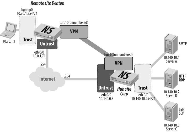
Figure 10-17 shows the layout for this scenario. The remote site “Denton” needs connectivity with the hub site “Corp” to gain access to server resources. Each location is configured with static IP addresses, and will use the default static route configuration within the trust VR.

This recipe starts by defining the protected resources on each end of the tunnel in the form of address objects. The following objects are defined at the hub site:
Corp-VPN-Hub->set address bb denton_lan 10.70.1.0/24Corp-VPN-Hub->set address trust local_lan 10.140.10.0/24
At the remote site, the following address objects are defined:
S1-Denton->set address bb corp_lan 10.140.10.0/24S1-Denton->set address trust local_lan 10.70.1.0/24
These address objects define the subnets on each end of the tunnel. In your environment, these could be address groups that contain specific addresses or ranges of IPs allowed to traverse the tunnel or be reached via the tunnel.
Next, you create the Phase-1 and Phase-2 configurations. The hub site has the following configuration:
Corp-VPN-Hub->set ike gateway denton address 10.0.1.71 main outgoing- Interface eth0/3 preshare juniper123 sec-level standardCorp-VPN-Hub->set vpn denton gateway denton sec-level standard
The remote site has the following configuration:
S1-Denton->set ike gateway corp address 10.140.0.3 main outgoing- preshare juniper123 sec-level standardS1-Denton->interface eth0/0 set vpn corp gateway corp sec-level standard
Here, you create the Phase-1 IKE gateway definition and configure it for the IPSec Main mode. Each site defines the remote IKE peer address and outgoing interface to be the local IKE peer as well as defines the preshared key and standard proposal. In the next line, you create the Phase-2 SA, bind it to the Phase-1 gateway definition, and configure a standard Phase-2 proposal. The final part of the configuration is to create bidirectional policies with a tunnel action that match the local and remote subnet addresses you defined in the first step.
At the hub site, configure the following policies to allow any IP-based communication between the sites:
Corp-VPN-Hub->set pol top name "to/from denton" from bb to trust denton_lan local_lan any tunnel vpn denton log count policy id = 5Corp-VPN-Hub->set pol top name "to/from denton" from trust to bb local_lan denton_lan any tunnel vpn denton log count policy id = 6
Policies at the remote site are as follows:
S1-Denton->set policy top name "to/from corp" from bb to trust corp_lan local_lan any tunnel vpn corp policy id = 13S1-Denton->set policy top name "to/from corp" from trust to bb local_lan corp_lan any tunnel vpn corp policy id = 14
In this scenario, the VPN monitor is also enabled with the rekey option. This configuration will keep the tunnel established at all times.
At the hub site, enable the VPN monitor for the denton VPN and save the configuration:
Corp-VPN-Hub->set vpn denton monitor rekeyCorp-VPN-Hub->save
Do the same for the remote site corp VPN:
S1-Denton->set vpn corp monitor rekeyS1-Denton->save
10.3. Route-Based IPSec Tunneling with Static Peers and Static Routes
Problem
You need to provide secure, encrypted traffic between two sites while enforcing firewall rules using a route-based configuration. These two sites have static IP addresses.
Solution
Create VPN configurations on each device using tunnel interfaces and policies.
Hub site configuration
For the hub site configuration, first create address entries for local and remote subnets:
Corp-VPN-Hub->set address trust local_lan 10.140.10.0/24Corp-VPN-Hub->set address vpn denton_lan 10.70.1.0/24
Then, create the zone and interface:
Corp-VPN-Hub->set zone name vpnCorp-VPN-Hub->set interf tun.10 zone vpnCorp-VPN-Hub->set interface tun.10 ip unnumbered interface eth0/3
Now, configure routes to use the tunnel for the destination subnet:
Corp-VPN-Hub-> set route 10.70.1.0/24 interface tun.10Next, configure the VPN Phase-1 and Phase-2 parameters:
Corp-VPN-Hub->set ike gateway denton address 10.0.1.71 main outgoing- Interface eth0/3 preshare juniper123 sec-level standardCorp-VPN-Hub->set vpn denton gateway denton sec-level standardCorp-VPN-Hub->set vpn denton bind interface tun.10
Enable the VPN monitor and rekey options:
Corp-VPN-Hub-> set vpn denton monitor rekeyFinally, create the bidirectional policies:
Corp-VPN-Hub->set policy from trust to vpn local_lan denton_lan any permit policy id = 5Corp-VPN-Hub->set pol from vpn to trust denton_lan local_lan any permit policy id = 6Corp-VPN-Hub->setave
Remote site configuration
For the remote site configuration, begin by creating address object entries for local and remote subnets:
S1-Denton->set address trust local_lan 10.70.1.0/24S1-Denton->set address vpn corp_lan 10.140.10.0/24
Create the zone and interface:
S1-Denton->set zone name vpnS1-Denton->set interface tun.10 zone vpnS1-Denton->set interface tun.10 ip unnumbered interface eth0/0
Now, configure the routes to use the tunnel for the destination subnet:
S1-Denton-> set route 10.140.10.0/24 interface tun.10Configure the VPN Phase-1 and Phase-2 parameters:
S1-Denton->set ike gateway corp address 10.140.0.3 main outgoing- interface eth0/0 preshare juniper123 sec-level standardS1-Denton->set vpn corp gateway corp sec-level standardS1-Denton->set vpn corp bind interface tun.10
Next, enable the VPN monitor and rekey options:
S1-Denton-> set vpn corp monitor rekeyFinally, create the policies permitting the traffic between zones:
S1-Denton->set policy from trust to vpn local_lan corp_lan any permit policy id = 13S1-Denton->set policy from vpn to trust corp_lan local_lan any permit policy id = 14S1-Denton->setave
Discussion
For this recipe, it is assumed that the firewall is already in operation and is configured, and that a new VPN tunnel needs to be created between two ScreenOS devices, as shown in Figure 10-18. This solution also uses a custom security zone in which to bind the VPN traffic. The VPN zone is now the encrypt/decrypt zone, and standard security policies may be used for permitting traffic from the tunnel to other zones, or from other zones into the tunnel.
Tip
You can place the tunnel interface into any zone. The caveat here is that when you’re using unnumbered tunnel interfaces, you can place the tunnel interface only within a zone bound to the same VR as the interface being used to borrow the IP address.
You could place the tunnel interface within the Trust zone. In this scenario, security policies would not be required for VPN traffic to communicate with hosts on the Trust zone without intra-zone blocking enabled. Intra-zone blocking is not enabled by default.
You begin this configuration by defining the protected resources at each site. You do this in the form of address and service objects. At the corporate site, the following is created:
Corp-VPN-Hub->set address trust local_lan 10.140.10.0/24Corp-VPN-Hub->set address vpn denton_lan 10.70.1.0/24
Two address objects are created to define the local and remote LANs. You can use address and service groups to specify strict communication parameters as desired. A similar configuration is performed for the remote site.
Next, the zone and tunnel interfaces are created:
Corp-VPN-Hub->set zone name vpnCorp-VPN-Hub->set interf tun.10 zone vpnCorp-VPN-Hub->set interface tun.10 ip unnumbered interface eth0/3
A custom security zone named VPN is created and is bound by default to the default VR (trust-vr) at both sites. An interface, tun.10, is created and bound to the VPN zone. This example of the corporate site uses an unnumbered interface, borrowing the IP address from interface eth0/3. At the remote site, interface eth0/0 is used for the tunnel interface IP address:
S1-Denton-> set interface tun.10 ip unnumbered interface eth0/0Next, you can add routes to direct traffic to the tunnel interface:
Corp-VPN-Hub->set route 10.70.1.0/24 interface tun.10S1-Denton->set route 10.140.10.0/24 interface tun.10
Now the IKE Phase-1 and Phase-2 parameters are specified. The two sites’ configurations are shown for comparison:
Corp-VPN-Hub->set ike gateway denton address 10.0.1.71 main outgoing- Interface eth0/3 preshare juniper123 sec-level standardCorp-VPN-Hub->set vpn denton gateway denton sec-level standardCorp-VPN-Hub->set vpn denton bind interface tun.10S1-Denton->set ike gateway corp address 10.140.0.3 main outgoing- interface eth0/0 preshare juniper123 sec-level standardS1-Denton->set vpn corp gateway corp sec-level standardS1-Denton->set vpn corp bind interface tun.10
Here, for convenience purposes, the same name is used for the IKE gateway and the VPN tunnel. Tunnels in opposite directions are configured using the same preshared keys and security levels. The VPNs are then bound to tun.10.
The VPN monitor and rekey are enabled on each end of the tunnel to ensure that the tunnel remains active and up at all times:
Corp-VPN-Hub-> set vpn denton monitor rekeyTo finish the configuration, policies are configured between the VPN and Trust zones to permit the traffic between the two subnets:
Corp-VPN-Hub->set policy from trust to vpn local_lan denton_lan any permit policy id = 5Corp-VPN-Hub->set pol from vpn to trust denton_lan local_lan any permit policy id = 6Corp-VPN-Hub->setave
The policies shown here permit any traffic between the defined local and remote LANs. Your policies would, and should, be specific to the flows that should be permitted across the VPN tunnel.
Troubleshooting this configuration would consist of using the get event, debug ike, get sa, and get ike cookie commands. With route-based VPNs, it is also useful to verify that the route to a destination is indeed via the tunnel interface. You can do this with get route ip <IP address>.
10.4. Route-Based VPN with Dynamic Peer and Static Routing
Problem
You want to create a VPN tunnel between a remote site and the hub site where the remote site receives a DIP address from the service provider.
Solution
Use a route-based VPN approach and an IPSec Aggressive mode configuration. Enable the VPN monitor to keep the tunnel active.
Hub site configuration
For the hub site configuration, first create address entries for local and remote subnets:
Corp-VPN-Hub->set address trust local_lan 10.140.10.0/24Corp-VPN-Hub->set address vpn denton_lan 10.70.1.0/24
Next, create the zone and interface:
Corp-VPN-Hub->set zone name vpnCorp-VPN-Hub->set interf tun.21 zone vpnCorp-VPN-Hub->set interface tun.21 ip unnumbered interface eth0/3
Then, configure the VPN Phase-1 and Phase-2 parameters:
Corp-VPN-Hub->set ike gateway denton dynamic [email protected] Aggressive outgoing-interface eth0/3 preshare juniper123 sec-level standardCorp-VPN-Hub->set vpn denton gateway denton sec-level standardCorp-VPN-Hub->set vpn denton bind interface tun.21
Enable the VPN monitor and rekey options:
Corp-VPN-Hub-> set vpn denton monitor rekeyNext, create the bidirectional policies:
Corp-VPN-Hub->set policy from trust to vpn local_lan denton_lan any permit policy id = 5Corp-VPN-Hub->set pol from vpn to trust denton_lan local_lan any permit policy id = 6
Now, configure the routes to use the tunnel for the destination subnet:
Corp-VPN-Hub->set route 10.70.1.0/24 interface tun.21Corp-VPN-Hub->save
Remote site configuration
For the remote site configuration, create the address object entries for local and remote subnets:
S1-Denton->set address trust local_lan 10.70.1.0/24S1-Denton->set address vpn corp_lan 10.140.10.0/24
Next, create the zone and interface:
S1-Denton->set zone name vpnS1-Denton->set interface tun.5 zone vpnS1-Denton->set interface tun.5 ip unnumbered interface eth0/0
Configure the VPN Phase-1 and Phase-2 parameters:
S1-Denton->set ike gateway corp address 10.140.0.3 aggressive local-id [email protected] outgoing-interface eth0/0 preshare juniper123 sec-level standardS1-Denton->set vpn corp gateway corp sec-level standardS1-Denton->set vpn corp bind interface tun.5
Enable the VPN monitor and rekey options:
S1-Denton-> set vpn corp monitor rekeyNow, create the policies permitting the traffic between zones:
S1-Denton->set policy from trust to vpn local_lan corp_lan any permit policy id = 13S1-Denton->set policy from vpn to trust corp_lan local_lan any permit policy id = 14
Finish by configuring the routes to use the tunnel for the destination subnet:
S1-Denton->set route 10.140.10.0/24 interface tun.10S1-Denton->save
Discussion
In this recipe’s discussion, as shown in Figure 10-19, it is assumed that the security devices are already configured for the environment and that a route-based VPN needs to be established between a statically configured device and a dynamic peer. In this example, the two sites are named “Corp” and “Denton”.

This configuration begins with the creation of address objects defining the subnets on each end of the tunnel. In a real network, these definitions should include specific host addresses and potentially custom service objects to be used in firewall policies that limit connectivity to only the allowed flows.
Corp-VPN-Hub->set address trust local_lan 10.140.10.0/24Corp-VPN-Hub->set address vpn denton_lan 10.70.1.0/24S1-Denton->set address trust local_lan 10.70.1.0/24S1-Denton->set address vpn corp_lan 10.140.10.0/24
A custom security zone named VPN is created at each site and is used to bind the tunnel interface within. In this configuration, the tunnel interface will use IP unnumbered addressing and will borrow the IP address from the interface in the Untrust zone. Interface tun.21 is used at the Corp site and tun.5 is defined at the Denton site:
Corp-VPN-Hub->set zone name vpnCorp-VPN-Hub->set interf tun.21 zone vpnCorp-VPN-Hub->set interface tun.21 ip unnumbered interface eth0/3S1-Denton->set zone name vpnS1-Denton->set interface tun.5 zone vpnS1-Denton->set interface tun.5 ip unnumbered interface eth0/0
Next, the Phase-1 and Phase-2 IKE configurations are completed. With a DIP address on one end of the tunnel, you cannot use the IPv4 address as the IKE ID. Instead, you must use an email address, certificate, or FQDN. In this example, an email address is used for the IKE ID of the Denton site. The IKE ID [email protected] is configured as the IKE ID to expect at the Corp site and as the local-id to send at the Denton site:
Corp-VPN-Hub->set ike gateway denton dynamic [email protected] aggressive outgoing-interface eth0/3 preshare juniper123 sec-level standardCorp-VPN-Hub->set vpn denton gateway denton sec-level standardCorp-VPN-Hub->set vpn denton bind interface tun.21S1-Denton->set ike gateway corp address 10.140.0.3 aggressive local-id [email protected] outgoing-interface eth0/0 preshare juniper123 sec-level standardS1-Denton->set vpn corp gateway corp sec-level standardS1-Denton->set vpn corp bind interface tun.5
In the preceding VPN configuration, the Corp site configuration specifies a dynamic address followed by the IKE ID expected for this IKE gateway. This is followed by specifying Aggressive mode, the interface to use as the IKE peer, the preshared key, and the security level which contains the Phase-1 proposals to offer or accept.
At the Denton site, the address of the Corp site is configured and Aggressive mode is specified for the Phase-1 exchange. The IKE ID in the form of local-id is configured, and will be used to identify the Denton site during the Phase-1 negotiations.
The remainder of the tunnel configuration is finished by configuring the Phase-2 security level and binding the tunnel to an interface.
Tip
When a participant in VPN uses a dynamically assigned IP address, that device must be the IKE initiator and must start the IPSec negotiations. You can use the VPN monitor with the rekey option to ensure that the tunnel initiates and stays active at all times.
The VPN monitor is configured with the rekey option to keep this tunnel in an active state:
Corp-VPN-Hub->set vpn denton monitor rekeyS1-Denton->set vpn corp monitor rekey
To finalize the configuration, policies and routes are created to steer traffic across the tunnel and permit specific flows through the stateful inspection engine:
Corp-VPN-Hub->set policy from trust to vpn local_lan denton_lan any permit policy id = 5Corp-VPN-Hub->set pol from vpn to trust denton_lan local_lan any permit policy id = 6Corp-VPN-Hub->set route 10.70.1.0/24 interface tun.21Corp-VPN-Hub->saveS1-Denton->set policy from trust to vpn local_lan corp_lan any permit policy id = 13S1-Denton->set policy from vpn to trust corp_lan local_lan any permit policy id = 14S1-Denton->set route 10.140.10.0/24 interface tun.10S1-Denton->save
Don’t forget to save your configuration.
This recipe is very similar to Recipe 10.3. The difference is with the Phase-1 exchange. Aggressive mode IKE is usually used when one end of the tunnel has a dynamically assigned IP address. Though not shown in this chapter, you also can use an FQDN as the address for the remote IKE peer. With Dynamic DNS (DDNS), this configuration could have used Main mode for the Phase-1 exchange even though the remote site has a dynamically assigned IP address.
For troubleshooting this configuration, use the get event, get sa, get ike cookie, and get route commands. Using debug ike commands can offer more verbose information regarding the success or failure of the IKE negotiations.
10.5. Redundant VPN Gateways with Static Routes
Problem
You want to create a VPN with a primary and a backup site with which remote offices can communicate. Static routing will be used with automatic rerouting around a failed primary tunnel.
Solution
Configure route-based tunnels to each hub site and use static routing with the VPN monitor to select the preferred or alternative path.
Primary hub site configuration
For the primary hub site configuration, start by creating the zone and interface:
Corp-VPN-Hub->set zone name vpnCorp-VPN-Hub->set interf tun.21 zone vpnCorp-VPN-Hub->set interface tun.21 ip unnumbered interface eth0/0
Now, create address entries for the local and remote subnets:
Corp-VPN-Hub->set address trust server_farm 10.88.10.0/24Corp-VPN-Hub->set address vpn denton_lan 10.70.1.0/24
Configure the VPN Phase-1 and Phase-2 parameters:
Corp-VPN-Hub->set ike gateway denton dynamic [email protected] Aggressive outgoing-interface eth0/3 preshare juniper123 sec-level standardCorp-VPN-Hub->set vpn denton gateway denton sec-level standardCorp-VPN-Hub->set vpn denton bind interface tun.21
Next, configure the routes to use the tunnel for the destination subnet:
Corp-VPN-Hub-> set route 10.70.1.0/24 interface tun.21Now, enable the VPN monitor and rekey options:
Corp-VPN-Hub-> set vpn denton monitor rekeyFinish by creating the bidirectional policies:
Corp-VPN-Hub->policy from trust to vpn local_lan denton_lan any permit policy id = 5Corp-VPN-Hub->pol from vpn to trust denton_lan local_lan any permit policy id = 6Corp-VPN-Hub->save
Backup hub site configuration
For the backup hub site configuration, start by creating the zone and interface:
Backup-Hub->set zone name vpnBackup-Hub->set interf tun.21 zone vpnBackup-Hub->set interface tun.21 ip unnumbered interface eth0/0
Create the address entries for the local and remote subnets:
Backup-Hub->set address trust server_farm 10.88.10.0/24Backup-Hub->set address vpn denton_lan 10.70.1.0/24
Now, configure the VPN Phase-1 and Phase-2 parameters:
Backup-Hub->set ike gateway denton dynamic [email protected] Aggressive outgoing-interface eth0/3 preshare juniper123 sec-level standardBackup-Hub->set vpn denton gateway denton sec-level standardBackup-Hub->set vpn denton bind interface tun.21
Configure the routes to use the tunnel for the destination subnet:
Backup-Hub-> set route 10.70.1.0/24 interface tun.21Next, enable the VPN monitor and rekey options:
Backup-VPN-Hub-> set vpn denton monitor rekeyFinally, create the bidirectional policies:
Backup-Hub->set policy from trust to vpn server_farm denton_lan any permit policy id = 5Backup-Hub->set pol from vpn to trust denton_lan server_farm any permit policy id = 6Backup-Hub->save
Remote site configuration
Start the remote site configuration by creating the zone and interface:
S1-Denton->set zone name vpnS1-Denton->set interface tun.5 zone vpnS1-Denton->set interface tun.5 ip unnumbered interface eth0/0
Now, create the address object entries for the local and remote subnets:
S1-Denton->set address trust denton_lan 10.70.1.0/24S1-Denton->set address vpn server_farm 10.88.10.0/24
Configure the VPN Phase-1 and Phase-2 parameters for the primary tunnel:
S1-Denton->set ike gateway corp address 10.140.0.3 aggressive local-id [email protected] outgoing-interface eth0/0 preshare juniper123 sec-level standardS1-Denton->set vpn corp gateway corp sec-level standardS1-Denton->set vpn corp bind interface tun.5
Next, configure the VPN Phase-1 and Phase-2 parameters for the backup tunnel:
S1-Denton->set ike gateway backup address 10.55.0.3 aggressive local-id [email protected] outgoing-interface eth0/0 preshare juniper123 sec-level standardS1-Denton->set vpn backup gateway backup sec-level standardS1-Denton->set vpn backup bind interface tun.5
Configure the routes and interface NHTB mapping:
S1-Denton->set route 10.88.10.0/24 interface tun.5 gateway 10.140.0.3 metric 10S1-Denton->set route 10.88.10.0/24 interface tun.5 gateway 10.55.0.3 metric 100S1-Denton->set interface tun.5 nhtb 10.140.0.3 vpn corpS1-Denton->set interface tun.5 nhtb 10.55.0.3 vpn backup
Now, enable the VPN monitor and rekey options (~10-second failover):
S1-Denton->set vpn corp monitor rekeyS1-Denton->set vpn backup monitor rekeyS1-Denton->set vpnmon interval 2S1-Denton->set vpnmon threshold 5
Create the policies permitting the traffic between zones:
S1-Denton->set policy from trust to vpn denton_lan server_farm any permit policy id = 13S1-Denton->set policy from vpn to trust server_farm denton_lan any permit policy id = 14S1-Denton->save
Discussion
In this example, as illustrated in Figure 10-20, the remote site “Denton” has two tunnels configured—one to each hub site, “Corp” and “Backup”. From the perspective of the remote site, static routes are configured for reaching the remote resources on subnet 10.88.10.0/24. Route metrics are used to prefer the tunnel between Denton and Corp. If the preferred tunnel should fail, the backup tunnel will be used to reach the remote resources. This example also demonstrates the use of NHTB for creating a point-to-multipoint interface. In other words, a single tunnel interface will be used to service both VPN tunnels from the remote site.

You begin the configuration by defining a custom security zone named VPN as well as an unnumbered tunnel interface within the zone at each site:
Corp-VPN-Hub->set zone name vpnCorp-VPN-Hub->set interf tun.21 zone vpnCorp-VPN-Hub->set interface tun.21 ip unnumbered interface eth0/0Backup-Hub->set zone name vpnBackup-Hub->set interf tun.21 zone vpnBackup-Hub->set interface tun.21 ip unnumbered interface eth0/0S1-Denton->set zone name vpnS1-Denton->set interface tun.5 zone vpnS1-Denton->set interface tun.5 ip unnumbered interface eth0/0
Next, the protected resources in the form of address objects are created. For simplicity’s sake, only the subnet hosting the resources and the remote LAN are defined in this example. You should replace this step with specific address groups and perhaps custom services defining the hosts and protocols that will be permitted across the VPN:
Corp-VPN-Hub->set address trust server_farm 10.88.10.0/24Corp-VPN-Hub->set address vpn denton_lan 10.70.1.0/24Backup-Hub->set address trust server_farm 10.88.10.0/24Backup-Hub->set address vpn denton_lan 10.70.1.0/24S1-Denton->set address trust local_lan 10.70.1.0/24S1-Denton->set address vpn server_farm 10.88.10.0/24
The address object server_farm is defined at both hub sites in the Trust zone and at the remote site in the VPN zone. The address denton_lan is defined at the hub sites in the VPN zone and at the remote site in the Trust zone.
As with Recipe 10.4, the Denton site will be configured as a dynamic peer, using an email address for the IKE ID:
Corp-VPN-Hub->set ike gateway denton dynamic [email protected] aggressive outgoing-interface eth0/3 preshare juniper123 sec-level standardCorp-VPN-Hub->set vpn denton gateway denton sec-level standardCorp-VPN-Hub->set vpn denton bind interface tun.21Backup-Hub->set ike gateway denton dynamic [email protected] aggressive outgoing-interface eth0/3 preshare juniper123 sec-level standardBackup-Hub->set vpn denton gateway denton sec-level standardBackup-Hub->set vpn denton bind interface tun.21
The IKE configuration at the two hub sites is identical in this example. Each defines a dynamic address and aggressive mode to be used for the Phase-1 negotiation, expecting the IKE ID [email protected]. A preshared key, an interface for the IKE peer, and a security level complete the Phase-1 parameters. The Phase-2 parameters specify the security level and bind the tunnel to interface tun.21.
At the remote site, two tunnels are configured, one to each hub site:
S1-Denton->set ike gateway corp address 10.140.0.3 aggressive local-id [email protected] outgoing-interface eth0/0 preshare juniper123 sec-level standardS1-Denton->set vpn corp gateway corp sec-level standardS1-Denton->set vpn corp bind interface tun.5S1-Denton->set ike gateway backup address 10.55.0.3 aggressive local-id [email protected] outgoing-interface eth0/0 preshare juniper123 sec-level standardS1-Denton->set vpn backup gateway backup sec-level standardS1-Denton->set vpn backup bind interface tun.5
The IKE gateway parameters define the IP address of the IKE peer at each hub site, specify Aggressive mode, and define the IKE ID to send during the Phase-1 negotiations. Interface eth0/0 is used for the IKE gateway, and the preshared key and security level are defined. Here, you can see that both VPN tunnels are being bound to the same interface, tun.5. You will need to configure a method to process flows via the correct VPN tunnel. This example uses static routes and NHTB for this purpose.
At the hub sites, a single tunnel is bound to the interface, so a simple route statement is all that is required to steer traffic across the tunnel:
set route 10.70.1.0/24 interface tun.21
At the remote site, a point-to-multipoint interface is used with multiple tunnels bound to the interface, so specifying a route simply to the interface is not enough:
S1-Denton->set route 10.88.10.0/24 interface tun.5 gateway 10.140.0.3 metric 10S1-Denton->set route 10.88.10.0/24 interface tun.5 gateway 10.55.0.3 metric 100S1-Denton->set interface tun.5 nhtb 10.140.0.3 vpn corpS1-Denton->set interface tun.5 nhtb 10.55.0.3 vpn backup
The route entries and NHTB definitions are the meat of this recipe. The remote site has a tunnel to each hub site. The set route commands specify that destination 10.88.10.0/24 can be reached via tun.1 with a next-hop gateway defined and a metric preferring the tunnel associated with gateway 10.140.0.3. The NHTB definitions that follow define which gateway is reachable via which tunnel. It is important to understand that the next-hop gateway addresses used in the route statement do not have to actually be reachable; they are simply pointers into the NHTB table so that the correct tunnel (SA) will be used as the traffic flow destination. Please see the “NHTB” section in the introduction to this chapter for more information.
Tip
In this example, ScreenOS could automatically create the NHTB configuration. It is shown statically configured here as an example of the command usage and could be omitted.
To finish the configuration, the VPN monitor is enabled to keep the tunnels active. In addition, the VPN monitor plays an important role in this scenario. If a tunnel fails, the VPN monitor will recognize the failure and mark any routes associated with the tunnel as inactive. This will allow the route with the next best metric to be used for flows to the specific destination(s). We explain the VPN monitor and the rekey option in more detail in the Introduction to this chapter.
set vpn denton monitor rekey set vpnmon interval 2 set vpnmon threshold 5 S1-Denton->set vpn corp monitor rekeyS1-Denton->set vpn backup monitor rekeyS1-Denton->set vpnmon interval 2S1-Denton->set vpnmon threshold 5
The same commands are used at the hub sites, and each VPN at the remote site gets the VPN monitor enabled. The interval and threshold for the VPN monitor are configured to send the ICMP packet every two seconds (interval) and to declare the tunnel as “down” if five pings are missed (threshold). This would provide a 10-second failover time.
Tip
When scaling VPN to a large design, be careful when choosing an interval and threshold for the VPN monitor, as the monitoring function does add traffic to the network. The default settings for the VPN monitor are interval = 10 and threshold = 10.
Policies are now applied for permitting specific flows to/from the VPN zone.
Here is how the route table, the SAs, the VPN monitor, and the NHTB table look for this design with no failures at the remote site.
We see bidirectional SAs between both gateways—the Corp and the Backup sites. The SA index is in the first column followed by the remote gateway address, the Phase-2 security parameters that were negotiated, the SPI, the lifetime in seconds, and the status indicating that both tunnels are active and up (A/U). A VPN monitor failure would show the SA as A/D (active/down).
	S1-Denton-> get sa active
	total configured sa: 2
	HEX ID   Gateway     Port Algorithm     SPI  Life:sec kb Sta PID vsys
	0000000d< 10.140.0.3 500 esp:3des/sha1 98a96b51  2408 unlim A/U   -1 0
	0000000d> 10.140.0.3 500 esp:3des/sha1 4958d759  2408 unlim A/U   -1 0
	0000000e<  10.55.0.3 500 esp:3des/sha1 98a96b52  3223 unlim A/U   -1 0
	0000000e>  10.55.0.3 500 esp:3des/sha1 64761c05  3223 unlim A/U   -1 0
	S1-Denton->
Two routes are available to destination 10.88.10.0/24. The route with next-hop gateway 10.140.0.3 has a lower metric and is shown as active with the * designation at the beginning next to the route ID:
	S1-Denton-> get route | i 10.88.10.0/24
	*55323      10.88.10.0/24     tun.5 10.140.0.3   S   20   10   Root
	 55324      10.88.10.0/24     tun.5  10.55.0.3   S   20  100   Root
	S1-Denton->
Interface tun.5 shows two VPNs bound to it—corp and backup. It also shows that it is in the VPN zone, that it is controlled by the trust-vr, as well as some other information. The NHTB table is also shown for this interface.
	S1-Denton-> get interf tun.5
	Interface tunnel.5:
	  description tunnel.5
	  number 20, if_info 8200, if_index 5, mode route
	  link ready
	  vsys Root, zone vpn, vr trust-vr
	  admin mtu 1500, operating mtu 1500, default mtu 1500
	  *ip 0.0.0.0/0 unnumbered, source interface ethernet0/0
	  *manage ip 0.0.0.0
	  bound vpn:
	    corp
	    backup

	  Next-Hop Tunnel Binding table
	  Flag Status Next-Hop(IP) tunnel-id VPN
	   S    R    10.140.0.3 0x0000000d corp
	   S    D    10.55.0.3 0x0000000e backup

	  pmtu-v4 disabled
	  ping disabled, telnet disabled, SSH disabled, SNMP disabled
	  web disabled, ident-reset disabled, SSL disabled
	  DNS Proxy disabled
	  OSPF disabled BGP disabled RIP enabled RIPng disabled mtrace
	disabled
	  PIM: not configured IGMP not configured
	  bandwidth: physical 0kbps, configured egress [gbw 0kbps mbw 0kbps]
	             configured ingress mbw 0kbps, current bw 0kbps
	             total allocated gbw 0kbps
	Number of SW session: 8039, hw sess err cnt 0
You can also view the VPN monitor status. Here, the VPN monitor has sent 497 pings and received all the replies across sa_index 4000000d:
S1-Denton->debug sa-mon allS1-Denton->get db strsa index(1) send count = 497, avail = 497, tunnel_info = 4000000d vpn monitor pkt is received: cookie = 1, result = 1 Found valid sa(1), missed slots = 1
You can use standard VPN troubleshooting commands such as get event, get route, get ike cookie, and debug ike to identify a misconfiguration or other issues.
10.6. Dynamic Route-Based VPN with RIPv2
Problem
You need to configure a VPN between multiple sites and use a dynamic routing protocol to distribute the route table.
Solution
Use route-based VPN configurations with RIPv2 enabled on the selected interfaces.
Primary hub site configuration
For the primary hub site configuration, start by creating the zone and interface:
Primary-Hub->set zone name vpnPrimary-Hub->set interface tun.11 zone vpnPrimary-Hub->set interface tun.11 ip 10.70.70.1/28
Now, configure the VPN Phase-1 and Phase-2 parameters:
Primary-Hub->set ike gateway denton dynamic [email protected] Aggressive outgoing-interface eth0/3 preshare juniper 123 sec-level standardPrimary-Hub->set vpn denton gateway denton sec-level standardPrimary-Hub->set vpn denton bind interface tun.11
Enable the VPN monitor and rekey options:
Primary-Hub->set vpn denton monitor rekeyPrimary-Hub->set vpnmon interval 2Primary-Hub->set vpnmon threshold 5
And enable RIP globally and on any interfaces necessary:
Primary-Hub->set vr trust-vr protocol ripPrimary-Hub->set vr trust-vr protocol rip enablePrimary-Hub->set interface tun.11 protocol rip enablePrimary-Hub->set vr trust-vr protocol rip demand-circuit
Now, create a static route to the resources via a private router:
	Primary-Hub-> set route 10.88.10.0/24 interface eth0/0 gateway
	              0.140.10.1
Configure redistribution of the static route into RIP:
Primary-Hub->set vr trust-vr access-list 88 permit ip 10.88.10.0/24 1Primary-Hub->set vr trust-vr route-map name dist-static88 permit 1Primary-Hub->set vr trust-vr route-map dist-static88 1 match ip 88Primary-Hub->set vr trust-vr protocol rip redistribute route-map dist-static88 protocol static
Create address entries for local and remote subnets:
Primary-Hub->set address trust server_farm 10.88.10.0/24Primary-Hub->set address vpn denton_lan 10.70.1.0/24
And finally, create the bidirectional policies:
Primary-Hub->set policy from trust to vpn local_lan denton_lan any Permit policy id = 5Primary-Hub->set pol from vpn to trust denton_lan local_lan any Permit policy id = 6Primary-Hub->save
Backup hub site configuration
For the backup hub site configuration, begin by creating a zone and interface:
Backup-VPN-Hub->set zone name vpnBackup-VPN-Hub->set interf tun.11 zone vpnBackup-VPN-Hub->set interface tun.11 ip 10.70.70.2/28
Configure the VPN Phase-1 and Phase-2 parameters:
Backup-VPN-Hub->set ike gateway denton dynamic [email protected] Aggressive outgoing-interface eth0/0 preshare juniper123 sec-level standardBackup-VPN-Hub->set vpn denton gateway denton sec-level standardBackup-VPN-Hub->set vpn denton bind interface tun.21
Now, enable the VPN monitor and rekey options:
Backup-VPN-Hub->set vpn denton monitor rekeyBackup-VPN-Hub->set vpnmon interval 2Backup-VPN-Hub->set vpnmon threshold 5
And enable RIP globally and on any interfaces necessary:
Backup-VPN-Hub->set vr trust-vr protocol ripBackup-VPN-Hub->set vr trust-vr protocol rip enableBackup-VPN-Hub->set interface tun.11 protocol rip enableBackup-VPN-Hub->set vr trust-vr protocol rip demand-circuit
Create a static route to the resources via a private router:
	Backup-VPN-Hub-> set route 10.88.10.0/24 interface eth0/1 gateway
	                 10.55.10.1
Configure redistribution of the static route into RIP:
Backup-VPN-Hub->set vr trust-vr access-list 88 permit ip 10.88.10.0/24 1Backup-VPN-Hub->set vr trust-vr route-map name dist-static88 permit 1Backup-VPNHub->set vr trust-vr route-map dist-static88 1 match ip 88Backup-VPN-Hub->set vr trust-vr protocol rip redistribute route-map dist-static88 protocol static
Now, create address entries for the local and remote subnets:
Backup-VPN-Hub->set address trust server_farm 10.88.10.0/24Backup-VPN-Hub->set address vpn denton_lan 10.70.1.0/24
And finally, create the bidirectional policies:
Backup-VPN-Hub->set policy from trust to vpn server_farm denton_lan any permit policy id = 5Backup-VPN-Hub->set pol from vpn to trust denton_lan server_farm any permit policy id = 6
Remote site configuration
For the remote site configuration, first create a zone and interface:
S1-Denton->set zone name vpnS1-Denton->set interface tun.5 zone vpnS1-Denton->set interface tun.5 ip unnumbered 10.70.70.3/28
Now, configure the VPN Phase-1 and Phase-2 parameters for the primary tunnel:
S1-Denton->set ike gateway primary address 10.140.0.3 aggressive local-id [email protected] outgoing-interface eth0/ preshare juniper123 sec-level standardS1-Denton->set vpn primary gateway corp sec-level standardS1-Denton->set vpn primary bind interface tun.5
Next, configure the VPN Phase-1 and Phase-2 parameters for the backup tunnel:
S1-Denton->set ike gateway backup address 10.55.0.3 aggressive local-id [email protected] outgoing-interface eth0/0 preshare juniper123 sec-level standardS1-Denton->set vpn backup gateway backup sec-level standardS1-Denton->set vpn backup bind interface tun.5
Configure the interface NHTB mapping:
S1-Denton->set interface tun.5 nhtb 10.70.70.1 vpn primaryS1-Denton->set interface tun.5 nhtb 10.70.70.2 vpn backup
Next, configure the routing protocol instances and enable the DRP on the appropriate interfaces:
S1-Denton->set vr trust-vr protocol ripS1-Denton->set vr trust-vr protocol rip enableS1-Denton->set interface tun.5 protocol rip enableS1-Denton->set vr trust-vr protocol rip demand-circuit
Configure an access list and route map for redistributing the subnet in the Trust zone:
S1-Denton->set vr trust access-list 20 permit ip 10.70.1.0/24S1-Denton->set vr trust route-map name redis-conn permitS1-Denton->set vr trust route-map redis-conn 1 match ip 20S1-Denton->set vr trust proto rip redistribute route-map redis-conn protocol connected
Now, enable the VPN monitor and rekey options (~10-second failover):
S1-Denton->set vpn corp monitor rekeyS1-Denton->set vpn backup monitor rekeyS1-Denton->set vpnmon interval 2S1-Denton->set vpnmon threshold 5
Create address object entries for the local and remote subnets:
S1-Denton->set address trust local_lan 10.70.1.0/24S1-Denton->set address vpn server_farm 10.88.10.0/24
Finally, create the policies permitting the traffic between zones:
S1-Denton->set policy from trust to vpn local_lan server_farm any Permit policy id = 13S1-Denton->set policy from vpn to trust server_farm local_lan any Permit policy id = 14
Discussion
This example, as illustrated in Figure 10-21, portrays an environment where a remote site requires connectivity to resources that can be reached via multiple paths through the network. Remote site Denton can reach resources on the 10.88.10.0/24 subnet via either a primary or a backup hub site. Path selection will be through the use of the dynamic routing protocol RIPv2. ScreenOS supports the BGP and the OSPF protocol as well, and you could use any of the supported routing protocols to populate the routing tables among the participants. We chose RIPv2 because it is the simplest and most scalable method and is typically used in combination with OSPF.

In the scenario depicted in this recipe, the protected resources are located on a private network that includes the primary and backup sites. Though not depicted in this recipe, you could easily export routes learned via the RIPv2 protocol into OSPF, which may be running on the private network. Please see Chapters Chapter 16 and Chapter 17 for more information on routing protocols and exporting static or DRP routes into OSPF or BGP.
This configuration begins by creating a custom security zone and binding a tunnel interface within it. When using dynamic routing protocols such as RIPv2, an interface participating in the routing protocol needs to have an IP address assigned to it and cannot use unnumbered addressing. Create the custom zone and interfaces at each site:
Primary-Hub->set zone name vpnPrimary-Hub->set interface tun.11 zone vpnPrimary-Hub->set interface tun.11 ip 10.70.70.1/28Backup-VPN-Hub->set zone name vpnBackup-VPN-Hub->set interf tun.11 zone vpnBackup-VPN-Hub->set interface tun.11 ip 10.70.70.2/28S1-Denton->set zone name vpnS1-Denton->set interface tun.5 zone vpnS1-Denton->set interface tun.5 ip unnumbered 10.70.70.3/28
Each interface is configured with an IP address within the 10.70.70.0/28 subnet and is bound to the VPN zone.
Next, the VPN is configured at the two hub sites and is bound to the tunnel interface created in the preceding step:
Primary-Hub->set ike gateway denton dynamic [email protected] aggressive outgoing-interface eth0/3 preshare juniper 123 sec-level standardPrimary-Hub->set vpn denton gateway denton sec-level standardPrimary-Hub->set vpn denton bind interface tun.11Backup-VPN-Hub->set ike gateway denton dynamic [email protected] aggressive outgoing-interface eth0/0 preshare juniper123 sec-level standardBackup-VPN-Hub->set vpn denton gateway denton sec-level standardBackup-VPN-Hub->set vpn denton bind interface tun.21
At the remote site, two VPN tunnels are configured, one to each hub site, but both tunnels are bound to the same tunnel interface, tun.5:
S1-Denton->set ike gateway primary address 10.140.0.3 aggressive local-id [email protected] outgoing-interface eth0/0 preshare juniper123 sec-level standardS1-Denton->set vpn primary gateway corp sec-level standardS1-Denton->set vpn primary bind interface tun.5S1-Denton->set ike gateway backup address 10.55.0.3 aggressive local-id [email protected] outgoing-interface eth0/0 preshare juniper123 sec-level standardS1-Denton->set vpn backup gateway backup sec-level standardS1-Denton->set vpn backup bind interface tun.5
In the preceding tunnel configurations, Aggressive mode IKE is configured, although Main mode would be completely acceptable if all sites were configured with static IP addresses on the interface used as the IKE peer. The remote site needs additional configuration because it is operating in a point-to-multipoint mode. So, the NHTB table is configured:
S1-Denton->set interface tun.5 nhtb 10.70.70.1 vpn primaryS1-Denton->set interface tun.5 nhtb 10.70.70.2 vpn backup
The VPN monitor with the rekey option is enabled at each site for each VPN tunnel to ensure that the tunnels are always active. In addition, the VPN monitor will act as a dead-peer detection mechanism, and will disable routes associated with failed tunnels. These state changes from up/down will be relayed via the routing protocol.
Primary-Hub->set vpn denton monitor rekeyPrimary-Hub->set vpnmon interval 2Primary-Hub->set vpnmon threshold 5Backup-VPN-Hub->set vpn denton monitor rekeyBackup-VPN-Hub->set vpnmon interval 2Backup-VPN-Hub->set vpnmon threshold 5S1-Denton->set vpn corp monitor rekeyS1-Denton->set vpn backup monitor rekeyS1-Denton->set vpnmon interval 2S1-Denton->set vpnmon threshold 5
The VPN monitor pings will be sent every two seconds, and will consider the tunnel down if five consecutive ping responses are missed.
For this example, a static route is defined at each hub site for reaching the resources on the 10.88.10.0/24 subnet. An access list and a route map are configured for redistributing this static route into the RIPv2 protocol:
Primary-Hub->set route 10.88.10.0/24 interface eth0/0 gateway 10.140.10.1Primary-Hub->set route 10.88.10.0/24 interface eth0/0 gateway 10.140.10.1Backup-VPN-Hub->set route 10.88.10.0/24 interface eth0/1 gateway 1 0.55.10.1
The dynamic routing protocol is now enabled in the VR and on the tunnel interfaces at each site:
Primary-Hub->set vr trust-vr protocol ripPrimary-Hub->set vr trust-vr protocol rip enablePrimary-Hub->set interface tun.11 protocol rip enablePrimary-Hub->set vr trust-vr protocol rip demand-circuitBackup-VPN-Hub->set vr trust-vr protocol ripBackup-VPN-Hub->set vr trust-vr protocol rip enableBackup-VPN-Hub->set interface tun.11 protocol rip enableBackup-VPN-Hub->set vr trust-vr protocol rip demand-circuitS1-Denton->set vr trust-vr protocol ripS1-Denton->set vr trust-vr protocol rip enableS1-Denton->set interface tun.5 protocol rip enableS1-Denton->set vr trust-vr protocol rip demand-circuit
Enabling a routing protocol in ScreenOS is a two-step process: first, the routing instance is configured, and next, the instance is enabled. Then, you can enable the routing protocol on selected or all interfaces. In this example, demand-circuit is used so that route updates will occur only when a change in routing is triggered by a failure or external route update. This enables RIP to act much like a shortest path first (SPF) protocol.
Lastly, in this configuration, policies are created to allow specific flows between the VPN and Trust zones at each site.
To look at this configuration, the following command shows both tunnels active and up:
	S1-Denton-> get sa
	total configured sa: 2
	HEX ID   Gateway     Port Algorithm     SPI   Life:sec   kb  Sta  PID  vsys
	00000010<  10.55.0.3 500 esp:3des/sha1 98a9d054  381   unlim  A/U  -1  0
	00000010>  10.55.0.3 500 esp:3des/sha1 f281aaa9  381   unlim  A/U  -1  0
	00000011< 10.140.0.3 500 esp:3des/sha1 98a9d055 3582   unlim  A/U  -1  0
	00000011> 10.140.0.3 500 esp:3des/sha1 4958d75e 3582   unlim  A/U  -1  0
	S1-Denton->
To see the routes associated with our protected resources on 10.88.10.0/24,we can use the following commands:
S1-Denton->get route | i 10.88.10.0/24*62618 10.88.10.0/24 tun.5 10.70.70.1 R 100 11 Root S1-Denton->get route ip 10.88.10.1Dest for 10.88.10.1 -------------------------------------------------------------------------- trust-vr : => 10.88.10.0/24 (id=62618) via 10.70.70.1 (vr: trust-vr) Interface tunnel.5 , metric 11 None
In the first command, we see an active route to the subnet which was learned from RIP via interface tun.5 with a next-hop gateway of 10.70.70.1.
Viewing the NHTB table shows that the primary VPN will be used to reach this gateway:
	S1-Denton-> get interf tun.5
	Interface tunnel.5:
	description tunnel.5
	number 20, if_info 8200, if_index 5, mode route
	link ready
	vsys Root, zone vpn, vr trust-vr
	admin mtu 1500, operating mtu 1500, default mtu 1500
	*ip 10.70.70.3/28
	*manage ip 10.70.70.3
	route-deny disable
	bound vpn:
	  backup
	  primary

	Next-Hop Tunnel Binding table
	Flag Status Next-Hop(IP) tunnel-id VPN
	S     U    10.70.70.2 0x00000010 backup
	      U    10.70.70.1 0x00000011 primary
You can use standard troubleshooting commands such as get event, get ike cookie, get sa active, and debug ike to identify a misconfiguration or other issue affecting tunnel establishment.
10.7. Interoperability
Problem
You want to create VPN connectivity with a Cisco router. You have noncontiguous subnets on each side of the tunnel, and you must maintain strict proxy ID matching on each SA.
Solution
Use a route-based VPN configuration with a unique Phase-2 SA for each pair of subnets that need to communicate across the tunnel. Policy-based routing is used to ensure that data enters the appropriate SA.
ScreenOS configuration
For the ScreenOS configuration, start by creating the zones and interfaces:
S1-Denton->set interface eth0/1 zone dmzS1-Denton->set interface eth0/1 ip 10.10.12.254/24S1-Denton->set interface eth0/1 routeS1-Denton->set interface bg0 zone trustS1-Denton->set interface bg0 ip 10.10.10.254/24S1-Denton->set interface bg0 routeS1-Denton->set interface eth0/0 zone untrustS1-Denton->set interface eth0/0 ip 10.100.1.1/24S1-Denton->set zone name vpnS1-Denton->set interface tun.1 zone vpnS1-Denton->set interface tun.1 ip unnumbered interface eth0/0S1-Denton->set interface tun.2 zone vpnS1-Denton->set interface tun.2 ip unnumbered interface eth0/0S1-Denton->set interface tun.3 zone vpnS1-Denton->set interface tun.3 ip unnumbered interface eth0/0S1-Denton->set interface tun.4 zone vpnS1-Denton->set interface tun.4 ip unnumbered interface eth0/0
Now, configure the default route:
	S1-Denton-> set route 0.0.0.0/0 interface eth0/0 gateway
	10.100.1.254
Configure the Phase-1 gateway with a custom proposal:
S1-Denton->set ike p1-proposal "psk-3des-sha-g2-12800" preshare group2 esp 3des sha-1 second 12800S1-Denton->set ike gateway "cisco1" address 10.200.1.1 main outgoing- Interface eth0/0 preshare juniper123 proposal"psk-3des-sha-g2-12800" S1-Denton->set ike respond-bad-spi 1
Next, create the four distinct Phase-2 SAs with a custom proposal:
S1-Denton->set ike p2-proposal "g2-esp-3des-sha-10800-28800" group2 esp 3des sha-1 second 10800 kbyte 28800S1-Denton->set vpn "cisco-a" gateway "cisco1" no-replay tunnel idletime 0 proposal "g2-esp-3des-sha-10800-28800"S1-Denton->set vpn "cisco-a" id bind interface tunnel.1S1-Denton->set vpn "cisco-a" proxy-id local-ip 10.10.10.0/24 remote-ip 10.20.10.0/24 "ANY"S1-Denton->set vpn "cisco-b" gateway "cisco1" no-replay tunnel idletime 0 proposal "g2-esp-3des-sha-10800-28800"S1-Denton->set vpn "cisco-b" bind interface tunnel.2S1-Denton->set vpn "cisco-b" proxy-id local-ip 10.10.10.0/24 remote-ip 10.20.20.0/24 "ANY"S1-Denton->set vpn "cisco-c" gateway "cisco1" no-replay tunnel idletime 0 proposal "g2-esp-3des-sha-10800-28800"S1-Denton->set vpn "cisco-c" bind interface tunnel.3S1-Denton->set vpn "cisco-c" proxy-id local-ip 10.10.12.0/24 remote-ip 10.20.20.0/24 "ANY"S1-Denton->set vpn "cisco-d" gateway "cisco1" no-replay tunnel idletime 0 proposal "g2-esp-3des-sha-10800-28800"S1-Denton->set vpn "cisco-d" bind interface tunnel.4S1-Denton->set vpn "cisco-d" proxy-id local-ip 10.10.12.0/24 remote-ip 10.20.10.0/24 "ANY"
Now, create the policy-based routing configuration:
S1-Denton->set access-list extended 1 src-ip 10.10.10.0/24 dst-ip 10.20.10.0/24 entry 1S1-Denton->set access-list extended 2 src-ip 10.10.10.0/24 dst-ip 10.20.20.0/24 entry 1S1-Denton->set access-list extended 3 src-ip 10.10.12.0/24 dst-ip 10.20.10.0/24 entry 1S1-Denton->set access-list extended 4 src-ip 10.10.12.0/24 dst-ip 10.20.20.0/24 entry 1S1-Denton->set match-group name Net-aS1-Denton->set match-group Net-a ext-acl 1 match-entry 1S1-Denton->set match-group name Net-bS1-Denton->set match-group Net-b ext-acl 2 match-entry 1S1-Denton->set match-group name Net-cS1-Denton->set match-group Net-c ext-acl 3 match-entry 1S1-Denton->set match-group name Net-dS1-Denton->set match-group Net-d ext-acl 4 match-entry 1S1-Denton->set action-group name VPN-aS1-Denton->set action-group VPN-a next-interface tunnel.1 action-entry 1S1-Denton->set action-group name VPN-bS1-Denton->set action-group VPN-b next-interface tunnel.2 action-entry 1S1-Denton->set action-group name VPN-cS1-Denton->set action-group VPN-c next-interface tunnel.3 action-entry 1S1-Denton->set action-group name VPN-dS1-Denton->set action-group VPN-d next-interface tunnel.4 action-entry 1S1-Denton->set pbr policy name VPNPBRS1-Denton->set pbr policy VPNPBR match-group Net-a action-group VPN-a 1S1-Denton->set pbr policy VPNPBR match-group Net-b action-group VPN-b 2S1-Denton->set pbr policy VPNPBR match-group Net-c action-group VPN-c 3S1-Denton->set pbr policy VPNPBR match-group Net-d action-group VPN-d 4
Lastly, add any firewall permit policies:
S1-Denton->set policy from trust to vpn any any any permit log countS1-Denton->set policy from vpn to trust any any any permit log countS1-Denton->set policy from dmz to vpn any any any permit log countS1-Denton->set policy from vpn to dmz any any any permit log count
Cisco configuration
The following Cisco configuration is provided as an example:
	CPE-IPSec-2#configure t
	Enter configuration commands, one per line. End with CNTL/Z.
	CPE-IPSec-2(config)#crypto isakmp policy 1
	CPE-IPSec-2(config-isakmp)#encr 3des
	CPE-IPSec-2(config-isakmp)#auth
	CPE-IPSec-2(config-isakmp)#authentication pre-share
	CPE-IPSec-2(config-isakmp)#group 2
	CPE-IPSec-2(config-isakmp)#lifetime 3600
	CPE-IPSec-2(config-isakmp)#exit
	CPE-IPSec-2(config)#crypto isakmp key juniper123 address 10.100.1.1
	CPE-IPSec-2(config)#crypto ipsec transform-set esp-3des-esp-sha-hmac
	esp-3des esp-sha-hmac
	CPE-IPSEC-2(config)#crypto map vpn 10 ipsec-isakmp
	% NOTE: This new crypto map will remain disabled until a peer
	        and a valid access list have been configured.
	CPE-IPSEC-2(config-crypto-map)#set peer 10.100.1.1
	CPE-IPSEC-2(config-crypto-map)#set security-association lifetime
	seconds 3600
	CPE-IPSEC-2(config-crypto-map)#set transform-set esp-3des-esp-sha-hmac
	CPE-IPSEC-2(config-crypto-map)#set pfs group2
	CPE-IPSEC-2(config-crypto-map)#match address 100
	CPE-IPSEC-2(config-crypto-map)#exit
	CPE-IPSEC-2(config)#int fastEthernet 0/0
	CPE-IPSEC-2(config-if)#crypto map VPN
	CPE-IPSEC-2(config-if)#exit
	CPE-IPSEC-2(config)#access-list 100 permit ip 10.20.10.0 0.0.0.255
	10.10.10.0 0.0.0.255
	CPE-IPSEC-2(config)#access-list 100 permit ip 10.20.200 0.0.0.255
	10.10.10.0 0.0.0.255
	CPE-IPSEC-2(config)#access-list 100 permit ip 10.20.10.0 0.0.0.255
	10.10.12.0 0.0.0.255
	CPE-IPSEC-2(config)#access-list 100 permit ip 10.20.200 0.0.0.255
	10.10.12.0 0.0.0.255
	CPE-IPSEC-2(config)#exit
	CPE-IPSEC-2#write mem
Discussion
This recipe is offered for those who need to create VPN connectivity between ScreenOS and third-party products, as illustrated in Figure 10-22. The Cisco configu-ration is shown as a default, but the concept and ScreenOS configuration should apply and interoperate with most VPN vendors’ IPSec standard-based implementations.
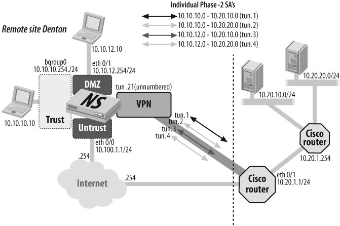
This recipe represents a worst-case scenario where you have noncontiguous subnets on each end of the tunnel. Between ScreenOS security devices, this is easy to solve by specifying a proxy ID of 0.0.0.0/0, allowing all traffic across the tunnel. This pro-vides ease in networking and rerouting while ScreenOS still provides secure traffic filtering with zone-based policies. However, many vendors have not taken this approach and require strict proxy ID matching. In this recipe, we use multiple Phase-2 SAs and logical tunnel interfaces to provide distinct paths for each pair of subnets that need to communicate with each other.
You begin by configuring your interface and putting the interfaces into the appropriate zones. Then, you create your tunnel interfaces and put them into the VPN zone. Here, we are using unnumbered interfaces and borrowing the IP address from eth0/0.
Configure any routes you may need. A default to the public network would be the minimum configuration.
Next, you create the Phase-1 gateway definition with a custom Phase-1 proposal that you plan to match on the Cisco end of the configuration:
S1-Denton->set ike p1-proposal "psk-3des-sha-g2-12800" preshare group2 esp 3des sha-1 second 12800S1-Denton->set ike gateway "cisco1" address 10.200.1.1 main outgoing- Interface eth0/0 preshare juniper123 proposal "psk-3des-sha-g2-12800"S1-Denton->set ike respond-bad-spi 1
A proposal named "psk-3des-sha-g2-12800" is created and configured for the preshared key, DH Group 2,and ESP using the 3DES and SHA-1 security options. Then, you create the Phase-1 gateway named "cisco1", specifying the Cisco interface IP as the gateway IP address, and choosing IKE Main mode negotiations with eth0/0 defined as the IKE peer. The preshared key juniper123 should match the Cisco configuration, as should the Phase-1 proposal that will be offered.
Now, you create the four distinct Phase-2 SAs for the purpose of matching the local and remote proxy IDs that will match the Cisco access control list (ACL) configuration. In addition, you create a custom Phase-2 proposal that will also be used on the Cisco device.
S1-Denton->set ike p2-proposal "g2-esp-3des-sha-10800-28800" group2 esp 3des sha-1 second 10800 kbyte 28800S1-Denton->set vpn "cisco-a" gateway "cisco1" no-replay tunnel idletime 0 proposal "g2-esp-3des-sha-10800-28800"S1-Denton->set vpn "cisco-a" id bind interface tunnel.1S1-Denton->set vpn "cisco-a" proxy-id local-ip 10.10.10.0/24 remote-ip 10.20.10.0/24 "ANY"S1-Denton->set vpn "cisco-b" gateway "cisco1" no-replay tunnel idletime 0 proposal "g2-esp-3des-sha-10800-28800"S1-Denton->set vpn "cisco-b" bind interface tunnel.2S1-Denton->set vpn "cisco-b" proxy-id local-ip 10.10.10.0/24 remote-ip 10.20.20.0/24 "ANY"S1-Denton->set vpn "cisco-c" gateway "cisco1" no-replay tunnel idletime 0 proposal "g2-esp-3des-sha-10800-28800"S1-Denton->set vpn "cisco-c" bind interface tunnel.3S1-Denton->set vpn "cisco-c" proxy-id local-ip 10.10.12.0/24 remote-ip 10.20.20.0/24 "ANY"S1-Denton->set vpn "cisco-d" gateway "cisco1" no-replay tunnel idletime 0 proposal "g2-esp-3des-sha-10800-28800"S1-Denton->set vpn "cisco-d" bind interface tunnel.4S1-Denton->set vpn "cisco-d" proxy-id local-ip 10.10.12.0/24remote-ip 10.20.10.0/24 "ANY"
Four different VPN definitions are created, named "cisco-a", "cisco-b", "cisco-c", and "cisco-d". Each is tied to the Phase-1 gateway definition, bound to a tunnel interface, and configured for the local and remote proxy IDs that match the Cisco ACLs.
Tip
The VPN monitor is not enabled in this configuration. However, you could use it with an advanced configuration. The VPN monitor traffic must also match the proxy IDs configured for each SA or the Cisco device will discard them. Therefore, you must specify the monitor’s source and destination addresses. In this scenario, you could use the interfaces in the Trust and DMZ zones as the source and a host in each remote subnet as the destination.
Because you have four distinct tunnels, you need to configure a mechanism to make sure you get the correct flows into the correct SA. One mechanism for accomplishing this is the NHTB mechanism. NHTB is fine for some scenarios where you need a simple point-to-multipoint interface configuration. However, it has proven ineffective for interoperability such as that shown in this scenario. NHTB only provides mapping into tunnels based on destination address. Here, you must strictly match source and destination addresses and process them across the appropriate SA, so a policy-based routing approach is used with multiple tunnel interfaces.
S1-Denton->set access-list extended 1 src-ip 10.10.10.0/24 dst-ip 10.20.10.0/24 entry 1S1-Denton->set access-list extended 2 src-ip 10.10.10.0/24 dst-ip 10.20.20.0/24 entry 1S1-Denton->set access-list extended 3 src-ip 10.10.12.0/24 dst-ip 10.20.10.0/24 entry 1S1-Denton->set access-list extended 4 src-ip 10.10.12.0/24 dst-ip 10.20.20.0/24 entry 1S1-Denton->set match-group name Net-aS1-Denton->set match-group Net-a ext-acl 1 match-entry 1S1-Denton->set match-group name Net-bS1-Denton->set match-group Net-b ext-acl 2 match-entry 1S1-Denton->set match-group name Net-cS1-Denton->set match-group Net-c ext-acl 3 match-entry 1S1-Denton->set match-group name Net-dS1-Denton->set match-group Net-d ext-acl 4 match-entry 1S1-Denton->set action-group name VPN-aS1-Denton->set action-group VPN-a next-interface tunnel.1 action-entry 1S1-Denton->set action-group name VPN-bS1-Denton->set action-group VPN-b next-interface tunnel.2 action-entry 1S1-Denton->set action-group name VPN-cS1-Denton->set action-group VPN-c next-interface tunnel.3 action-entry 1S1-Denton->set action-group name VPN-dS1-Denton->set action-group VPN-d next-interface tunnel.4 action-entry 1S1-Denton->set pbr policy name VPNPBRS1-Denton->set pbr policy VPNPBR match-group Net-a action-group VPN-a 1S1-Denton->set pbr policy VPNPBR match-group Net-b action-group VPN-b 2S1-Denton->set pbr policy VPNPBR match-group Net-c action-group VPN-c 3S1-Denton->set pbr policy VPNPBR match-group Net-d action-group VPN-d 4
First, you create your ACLs to match your four different sets of proxy IDs/SAs. Then, you create your match groups associated with the extended ACL definitions. Here, the match groups are named Net-a, Net-b, Net-c, and Net-d to stay within our naming convention. Next, you configure an action group. This is where you map to the appropriate interface as a next hop. The names VPN-a, VPN-b, VPN-c, iand VPN-d are mapped to our tunnel interfaces bound to the appropriate SA. Lastly, you create a policy linking the match group to the action group.
The VPN configuration is complete. Now, you can add any policies you may require to permit specific flows between the subnet pairs:
S1-Denton->set policy from trust to vpn any any any permit log countS1-Denton->set policy from vpn to trust any any any permit log countS1-Denton->set policy from dmz to vpn any any any permit log countS1-Denton->set policy from vpn to dmz any any any permit log count
Tip
Policies shown here are for ease of presentation. You should definitely create custom address objects and policies that are suitable for your environment.
Troubleshooting commands for this scenario include the following:
S1-Denton->get ike cookieS1-Denton->get saS1-Denton->get eventS1-Denton->get log trafficS1-Denton->debug ike