
Anti-burglary security circuits
The best known and most widely used type of electronic security unit is the so-called ‘burglar alarm’, which is usually designed to detect burglars attempting to break into protected premises while at the same time letting authorized individuals roam freely within those premises and to easily enter or leave their perimeter zones. It is important to understand that normal burglar alarms are last-resort devices that cannot be used on a ‘stand alone’ basis to give good protection against burglary; to give good protection, they must always be used in conjunction with various physical defences/deterrents and with mechanical security devices such as locks, latches, and security windows, and their sensors and sirens must be located to give the best possible security to the individual premises that are being protected. Note that the main aim of an anti-burglary security system is that of deterring potential burglars from even trying to break into the defended premises; the burglar alarm is simply a back-up to that system and activates when a burglary is actually in progress, and is thus of value only if the main deterrent security system fails in its task.
To get the best value from any burglar alarm the user must first learn the basic principles of anti-burglary protection, and must then use that knowledge to convert the basic burglar alarm into a device that gives a performance that is tailored to suit some specific security application. This chapter gives a concise outline of these various principles, and then goes on to show a variety of practical domestic-type burglar alarm and accessory circuits.
Anti-burglary basics
A burglar is a person who forcibly enters houses or other premises with the intention of theft. To be burgled is a vile experience. At best, the burglar may be a professional who will enter your home and steal many of your personal possessions, some of which will have a sentimental value far in excess of their insured monetary cost; the next day that same burglar will probably sell those precious goods for a trivial amount of money, and then go and rob someone else. At worst, your burglar may be a demented amateur who enters your home with a heart full of hate, intent on stealing your cash and destroying or desecrating everything else; he will slash your furniture and clothes, urinate on your bedding, smear excrement and paint on your walls, and try to smash or burn everything else; this type of burglary is so repulsive that many victims never recover from the psychological damage caused by the experience.
Your vulnerability to burglary is greatly influenced by the location and nature of the premises in which you live or work, and by the security precautions that you take to protect those premises. In all advanced Western countries, annual burglary totals are proportional to national population figures, and are typified by those of the UK, which has a total population of about 56 000 000. In the UK, the annual total of burglaries in the ten years up to 1997 averaged about 900 000, of which approximately 400 000 were domestic burglaries. Of these domestic incidents, almost three quarters involved actual physical forced entry, and more than a quarter were walk-in burglaries in which the intruder entered the premises via an unlocked door or window or (in a small number of cases) by using a carelessly hidden spare front door key.
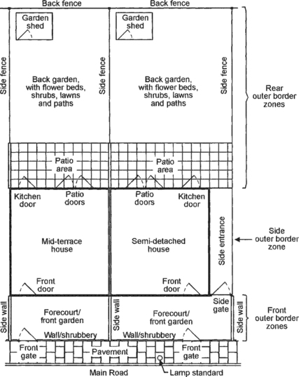
For security purposes, all private premises can be regarded as defensible fortresses (houses or other buildings) that are surrounded by defensible outer border zones (private land, with outer fences and hedges, etc.). No burglar can reach your private fortress without first passing through at least one of its outer border zones, which thus form your first and most important anti-burglary defence areas; if you use these areas sensibly, you will deter most burglars from even trying to break into your house. Figure 4.1 and the next two major sections of text help illustrate some of the basic defence principles of these areas, specifically applied to medium-sized mid-terrace and semi-detached houses of the types found in many suburban areas in the UK.
Front outer border defence zones
Most burglars make an unobtrusive visual study of a building by walking or driving casually past it to determine whether or not it seems an easy or a not-worth-the-risk target for burglary. Their main aim is to get into and out of the premises unobtrusively, and they thus like houses that have their front gardens enclosed by high shrubs or bushes, or are shrouded in darkness at night, and seem to be unoccupied and to have no obvious anti-burglary protection. Many potential burglars can be scared off by taking simple precautions such as fitting the building with time switches that automatically operate house lights at various times, or by leaving a radio switched on when the house is empty, or by fitting a real or dummy alarm bell housing to the front of the house.
One priceless anti-burglary device is the nosey but trustworthy neighbour who, if asked, will keep an eye on your house front when you are away on holiday, and will immediately summon help if anything suspicious is seen. Treat such people kindly, and try to gain their friendship.
If burglars decide to attack a house from the front, they usually enter the garden via the front gate and then try to enter the house by the front door or – if the house has a side entrance – by forcing the side gate and then entering the house from the rear. Burglars know that some people hide a spare front door key under a flower pot or porch mat or on a porch ledge when they leave the house, and burglars often make a quick search for such a key when they enter the porch. You can take advantage of this fact by making a simple ‘false key’ booby trap that activates a self-latching alarm if an object such as a flower pot is briefly moved, or if someone grabs a key that is tied to a microswitch by a short length of string, etc. Thus, basic rules for protecting the house against frontal attack are as follows, and are illustrated in Figures 4.2 and 4.3:
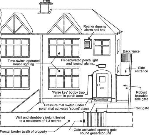
Figure 4.2 Diagram showing various burglar deterrents used in the front outer border zone of a semi-detached house
(1) Limit all front garden shrubbery to a maximum height of 1.3 metres.
(2) If your house front is poorly lit at night, fit it with an automatic PIR-activated porch lighting system.
(3) If your front gate is a self-closing type, fit it with a device that generates a distinctive sound as the gate is opened.
(4) If your front porch is not fitted with automatic PIR-activated lighting but does have a porch mat, place a pressure mat switch under the porch mat and use it to activate some clearly audible or visual warning device when anyone treads on the porch mat.
(5) Deter burglars by fitting a real or dummy alarm bell box to the front of the house, by fitting the house with time-switch operated lighting, and by leaving a radio turned on when the house is unoccupied.
(6) Fit a simple ‘false key’ booby trap in the porch area.
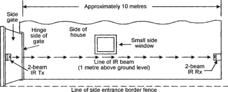
(7) If you have a side entrance, make sure that it is fitted with a robust and lockable side gate, at the house-front end of the entrance. Fit the side entrance with some type of intrusion-detecting alarm device that will activate if any unauthorized person enters the side entrance (even if they do so by climbing the gate), but will not be activated by cats, etc. House side entrances have a typical length of about 10 metres and are best defended by a PIR alarm fitted with a ‘corridor’ type of lens, or by an IR dual ‘light-beam’ alarm of the type described in Chapter 3 of this book; Figure 4.3 shows the basic arrangement of a suitable 2-beam IR light-beam alarm system.
In Figure 4.3 the IR dual-beam transmitter (Tx) is fixed to the side gate, near its ‘fence’ edge, and is aimed diagonally along the length of the side entrance, at a height of about 1 metre, towards the IR receiver (Rx) unit, which is fixed to the house wall at the far end of the entrance. Thus, the beam’s Tx to Rx contact will be broken if the gate is opened, or if any adult person moves along the side entrance when the gate is closed. Note that in this ‘slow movement’ type of application the system will work adequately if the Tx unit sends a 1mS high-frequency test pulse once every 200mS or so; thus, if this test pulse has a peak amplitude of (say) 100mA, the Tx unit may consume a mean current of only 250μA. The Tx and Rx units can thus easily be continuously operated and powered by rechargeable battery units that are trickle charged (from a single mains-powered unit) via a pair of low-voltage low-current leads.
Rear outer border defence zones
Three-quarters of all house break-ins occur at the back of the house (where the burglar is least likely to be seen), usually via a window. To reach the house, the burglar must cross the garden and patio areas, and usually reaches these by climbing a back or side fence or via a side entrance. Houses with rear access via a shared passage or driveway are particularly vulnerable to this type of break-in. Once a burglar has broken into one house, he can easily gain access to adjacent houses by climbing over their side fences, sometimes breaking into several houses or their sheds or garages in a short space of time. Thus, basic rules for protecting the house against attack from the rear are as follows, and in some cases are illustrated in Figure 4.4:
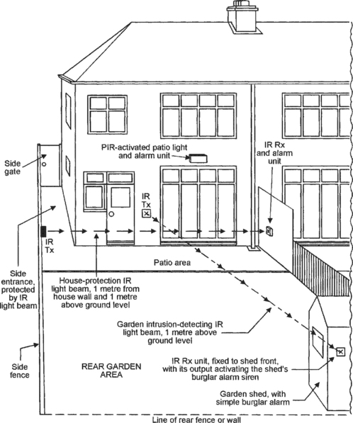
Figure 4.4 Diagram showing various burglar deterrents used in the rear border zone of a semi-detached house
(1) Burglars treat garden sheds and garages as valuable sources of tools and equipment for the break-in and for later sale, and often break into them before attacking the actual house. Thus, always fit your shed and garage with a simple battery-powered burglar alarm that activates a loud siren and a light strobe if not disabled (via a secret switch) within about 20 seconds of opening the shed/garage door.
(2) If you keep a ladder in the rear defence area, wire it to a simple ‘loop’ alarm (see Chapter 2), so that the alarm sounds if the ladder is forcibly moved.
(3) If your house has rear access via a passage or driveway, protect the top of your back fence/wall with barbed wire or in some other way.
(4) It is not practical to protect side fences against a burglar who wants to climb over them. Usually, however, the burglar is climbing them to reach the back of your house via the patio area, which can easily be protected via a PIR-activated flood-light/alarm unit or an IR light-beam alarm unit that is aimed along the back of the house a metre or so above ground level, as shown in Figure 4.4. If an IR light-beam is used, it must be positioned so that its beam can not be broken by carelessly placed patio furniture or by growing shrubbery.
(5) Sometimes the burglar may climb your garden fences to reach an adjacent property. You can detect this type of intrusion with an IR light-beam alarm unit that is aimed along the length of the garden, between the house and the garden shed (see Figure 4.4).
(6) If your house has a shared side entrance that leads to a pair of garages, mount a cheap dummy TV camera (with a built-in flashing LED that is powered from a remote battery) in a hard-to-reach position on the apex of the garages, aiming it along the entrance so that it is clearly visible from the street, as a burglar deterrent.
Front-door robbers
The easiest way to get into someone’s house is to simply knock on its front door and, when it opens, either barge or trick your way into the premises. Small-time crooks (including small children) often use the latter technique to carry out petty robberies, typically arriving as a pair and getting into the house on a flimsy pretext such as using your phone to make an emergency call, or asking for a glass of water, etc. One of the pair then keeps you busy with idle chit-chat while the other person searches the house for loose cash and trinkets. The basic rules for protecting yourself against this type of robbery are as follows:
(1) Fit your front door with a security chain, and never unhook it unless you are sure it is safe to do so.
(2) Buy a fixed or mobile self-latching panic-button alarm, and keep your finger on its button whenever you open the front door to a stranger.
(3) Never allow anyone (including children) into your house unless you are absolutely sure it is safe to do so.
(4) Never, under any circumstances, allow two or more strangers (particularly innocent looking children) into your house at the same time.
(5) Never, ever, under any circumstances, leave a total stranger alone in any part of your house; if they have the impertinence to ask to be left alone (to make a ‘private’ telephone call), immediately order them to leave the house, sound your panic alarm, and – as soon as they leave – call the local police.
The house
If the would-be burglar has successfully passed through your building’s outer border defence zones, he will now start to do physical and costly damage to the actual building by trying to break into it. His chances of breaking in are reduced (but the cost of the inflicted damage is increased) if the house is fitted with strong outer doors with robust locks/latches, and with double-glazed self-locking windows. You can greatly reduce the crook’s chances of committing a successful burglary by fitting the house (or other building) with a properly designed burglar alarm system.
Any building can, for crime prevention purposes, be regarded as a box that forms an enclosing perimeter around a number of interconnected compartments. This ‘box’ is the shell of the building, and contains walls, floors, ceilings, doors and windows. To commit any crime within the building, the intruder must first break through this shell, which thus forms the owner’s first line of house defence. In most houses, the most vulnerable parts of the shell are its doors and windows, but ceilings are also vulnerable (often via a trap door and loft space) in some top-floor flats and apartments and in many commercial buildings.
Once an intruder has entered the building, he can move from one room or compartment to the next only along paths that are predetermined by the layout of internal doors and passages. In moving from one compartment to the next he must inevitably pass over or through certain spots or areas in the building, as is made clear in Figure 4.5, which shows the ground-floor plan of a medium-sized house, together with suitable positions for anti-burglary devices/sensors such as PIR movement detectors, pressure mat switches, and reed-and-magnet ‘contact’ switches.
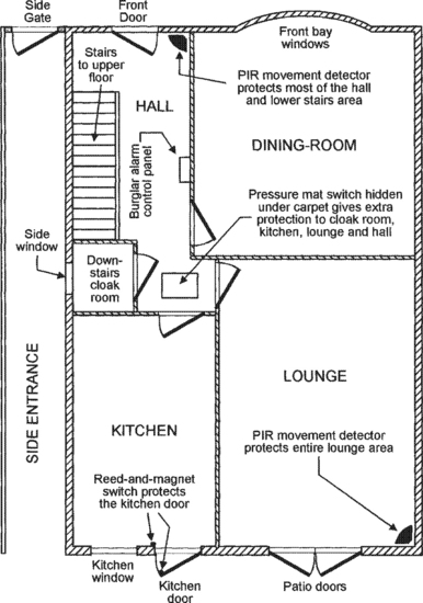
Figure 4.5 Ground-floor plan of a semi-detached house, showing suitable positions for anti-burglary defences
Thus, if an intruder breaks into this house via the kitchen (which has its outer door protected by a reed-and-magnet contact switch), or via the downstairs cloak room (via the side window), he can only reach the rest of the house by entering the hall, which is well protected by a hidden pressure mat switch and by a PIR movement detector, which also protects the front door and most of the stairway. The entire lounge is well protected by another PIR unit, which is aimed away from direct sunlight (a common cause of false alarms in PIR units) but will respond instantly if anyone enters the room via its main door or its patio doors. The dining-room is not individually protected, since it can only be accessed by its doorway (which is protected by the hall’s PIR unit), or via its bay window, which (if the windows are clearly visible from the street) is a very unlikely attack point. Thus, the entire ground floor of this house is adequately protected by just two PIR units and two detector switches. The upper floor can be protected with similar simplicity.
Note in Figure 4.5 that the burglar alarm’s main control panel is situated in the hall, where it can be conveniently operated (via a security key) on entering or leaving the house, or prior to going up the stairs (to go to bed), or immediately after coming down the stairs (after getting out of bed). The basic operating details of the burglar alarm system and its control panel are described in the next major section of this chapter.
Burglar alarm basics
Most modern domestic burglar alarm systems consist of a number of switched-output intrusion sensors (contact switches and PIR units, etc.) and a ‘panic’ button, which have their outputs coupled to the inputs of a master control unit that processes the received signals and, when appropriate, activates a built-in medium-power audible alarm and can, if required, also activate a high-power external siren or bell. The burglar alarm system’s block diagram thus takes the basic form shown in Figure 4.6.
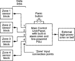
Note in Figure 4.6 that the alarm sensors are arranged in blocks or groups, each of which is allocated a specific ‘zone’ input connection point on the main control unit. The basic idea here is to divide your property into a number of distinct defence zones, each of which can cover any desired area and can have its defences enabled or disabled via the master control unit’s control panel. Suppose that the house shown in Figures 4.1 to 4.5 is divided up into the following four defence zones:
Zone 1 = External defences (shed, side-entrance, patio and garden).
Zone 2 = Entire upper floor of the house.
Zone 3 = The ground floor, except the lounge and the hall pressure mat.
Zone 4 = The lounge and the hall pressure mat.
With this defence system, superb round-the-clock anti-burglary protection can be obtained by switching the zones in the following ways, to suit the following circumstances:
When the house is empty, all four zones should be enabled, thus giving total protection. When the house is occupied during normal daylight hours but the garden area is unused, only Zone 1 should be enabled. If only the garden and ground floor are in use, only Zone 2 should be enabled. In the evening, if only the lounge is in use, Zones 1, 2 and 3 should all be enabled, thus protecting the occupier against the opportunist burglar who sneaks into the building while the family is watching TV in the evening (almost a quarter of all domestic burglaries occur when the house is occupied, with the occupiers either watching TV or asleep in bed). At night, when only the upper floor of the house is occupied, Zones 1, 3 and 4 should all be enabled. Note that the ‘panic’ button is normally enabled even when all four zones are disabled, thus giving the owner non-stop protection against thugs.
Entry/exit delay
In the basic type of system described above, the Zone 1, 2 and 4 defence circuitry is arranged so that, when these zones are active, the alarm sounds instantly if an intrusion is detected, but the Zone 3 defence circuitry (which protects the front door entry/exit and control panel areas) has a built-in ‘entry/exit’ operating delay of (typically) about 45 seconds. This delay gives the system’s key-holder limited freedom to pass through the Zone 3 defence area (to enter or leave the house or to operate the control panel) without sounding the alarm. This delay action is such that, when the owner enables Zone 3 via a key-switch prior to leaving the house or going to bed, the zone does not become active until the end of the 45 second ‘exit delay’ period; when the owner later passes through Zone 3 again to deactivate the zone via the key-switch, the zone’s sensors instantly detect the intrusion and activate a low-level ‘warning’ bleeper, but only activate the main alarm siren if the owner fails to disable the zone (or reset the alarm) via the key-switch by the end of the 45 second ‘entry’ delay period.
Thus, the Zone 3 entry/exit delay facility allows the alarm’s key holder to move reasonably freely about the house without activating the main alarm siren, but gives full protection against unwanted intruders who do not have access to the security key.
The main control unit/panel
The main control unit is the effective ‘heart’ of the burglar alarm system, and can be managed via a control panel. In simple units, the panel enables the unit’s main functions to be selected via a 4-way master key-switch (usually marked TEST, OFF, ON, and RESET). Most modern control units take the basic form shown in Figure 4.7 and are powered from the domestic AC power lines via a built-in DC PSU that also provides an auxiliary DC power output. The control unit should ideally also have a built-in rechargeable battery that is normally trickle-charged by the PSU but takes over the PSU’s main functions if the AC supply fails or is deliberately interrupted.

Modern control units usually have a built-in medium-power siren, plus a facility for activating a high-power external siren; ideally, the external siren should (to minimize the chances of generating publicly annoying false alarms) not activate until at least 30 seconds after the built-in siren has activated, and must (to conform to local noise control regulations) turn off automatically after a maximum period of about 15 minutes. Most units also have a built-in ‘tamper’ switch that (except when the master key is set to the TEST or RESET positions) activates the built-in self-latching siren if the unit’s case is opened.
The unit’s control panel usually takes the basic form shown in Figure 4.7, but in practice often uses electronic key-pad (rather than electromechanical) control switching. In this diagram, key-operated switch S1 selects the units main functions, and toggle switches S2 to S5 allow individual defence zones to be enabled or disabled. When S1 is set to the TEST position, the unit’s tamper switch and the external alarm are disabled, and the internal alarm operates in the non-latching mode. When S1 is set to the ON positions, the system is fully active and the internal alarm operates in the self-latching mode. When S1 is set to OFF, all four sensor zones are disabled, but the self-latching PANIC facility is fully active. If the alarm is activated in the self-latching mode, the alarm can only be turned off by first removing the cause of activation and then unlatching the alarm by moving S1 to the RESET position.
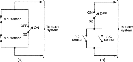
In traditional hard-wired alarm systems, the sensors that connect to the alarm’s various ‘zone’ input points usually take the effective forms of contact switches, which can easily be enabled or disabled by the S2 to S5 toggle switches shown in Figure 4.7. Figure 4.8 shows the connections for turning individual sections of the alarm sensor network on or off. Series-connected n.c. sensor networks can be enabled or disabled by wiring them in parallel with S2, as shown in Figure 4.8(a); the sensors are enabled when S2 is open, and are disabled when S2 is closed. Parallel-connected n.o. sensor networks can be enabled and disabled by wiring them in series with S2, as shown in Figure 4.8(b); the sensors are enabled when S1 is closed, and are disabled when S1 is open.
The external siren/alarm
The medium-power siren built into most modern control units usually drives an efficient piezoelectric output transducer and operates at a fairly high audio frequency (typically 1.5kHz to 4kHz); this type of siren floods the house with sound, but such sound attenuates rapidly with distance. Sirens designed for external use normally use an efficient horn-type loudspeaker as their output transducer and typically operate in the 800Hz to 1.2kHz audio range, which offers good long-distance acoustic coverage. Both types of siren normally generate an attention-grabbing multi-tone (pulsed, warbled, or swept) sound, rather than a tiresome monotone sound.
External sirens are usually enclosed in a weather-proof bell-type alarm box that is screwed to the house front; the box often incorporates a flashing alarm beacon that activates at the same time as the siren. Low-cost units of this type are usually powered, via a multi-cored cable, from the auxiliary power output terminals of the main control unit, and can be disabled by simply severing the power cable, which must thus be protected by burying it in brickwork, etc. High-quality external siren units, on the other hand, are self-powered and tamper-proof, and should (to conform to current design standards) meet the following basic design specifications:
(1) The siren must be powered by an internal rechargeable battery that is automatically trickle charged in some way and has enough capacity to provide at least 4 hours of continuous alarm operation.
(2) The unit must be designed so that the alarm is not triggered by a temporary failure in the trickle charging system, but will trigger if activated by the main control unit or if the unit’s main feed cable is cut.
(3) The box must incorporate tamper switches that automatically activate the alarm if the box’s cover is removed, or if the complete unit is forcibly removed from its fixing point (the wall).
(4) The unit must incorporate a timing mechanism that automatically resets the siren (but not necessarily the beacon) after (typically) not more that 15 minutes of continuous operation.
Figure 4.9 shows the block diagram of a typical high-quality external siren unit that satisfies the above design criteria, and is powered by a built-in battery that is trickle charged via the control unit’s auxiliary DC output terminals. This system is designed so that the control unit’s ‘alarm’ output is connected to the siren unit’s input via normally-closed (n.c.) switch S1, which is loop-wired in series with the siren unit’s two built-in n.c. tamper switches; one of these (S2) is connected to the unit’s box cover and opens if the cover is removed; the other (S3) is connected to the unit’s back plate and opens if the unit is pulled away from the wall. Thus, the siren activates if S1 opens, or if the main feed cable is cut, or if the box cover is removed, or if the unit’s back plate is torn from the wall. If any of these conditions occur, the unit’s built-in light strobe unit activates for the duration of the open circuit condition (or until the battery is exhausted), but the multi-tone siren (which is controlled by a 15-minute auto-timer and control logic) activates as soon as the open circuit condition occurs but resets again when the open circuit condition ends or, if the open circuit condition persists, after a maximum of 15 minutes. The siren may then turn off until the control unit is reset, or may reactivate again after a short delay, depending on the auto-timer design.

Note that the unit shown in Figure 4.9 is connected to the main control unit via a 4-core cable, with two cores dedicated to the trickle charger function and the other two to the ‘alarm’ signal. In some units, however, the siren and light strobe units are individually activated by the main control unit, and in such cases a 6-core cable may be used.
Wired versus wireless alarm systems
Modern commercial burglar alarm systems are usually microcontroller based, use a key-pad type of control panel, and incorporate an event recorder that – if a break-in occurs – records the precise order in which the various defence zones are invaded. Such systems come in two basic types, being either ‘wired’ or ‘wireless’ systems. In wired systems, all zone sensors (PIR movement detectors, contact switches, etc.) are cable wired to the main control unit, which in turn is wired to the external siren unit; such units are time consuming and (since they use lots of interconnection cable) messy to install. In wireless systems, all major zone sensors incorporate a wireless Tx unit that communicates (via a coded 418MHz or 458MHz RF signal) with a matching wireless Rx unit that is built into the main control unit; the Tx unit signals to the Rx unit if an alarm, tamper, or low-battery condition occurs; such systems are very easy and clean to install, but are considerably more expensive that normal wired systems.
All domestic wireless systems are provided with a key-fob style Tx unit that can be used to remotely set or unset the main alarm unit and to act as a ‘panic’ switch that can remotely activate the alarm siren at any time. Sensor units such as contact and PIR transmitters are battery powered (usually by a PP3 type battery) and, in approved designs, give at least six month of continuous operation per battery charge. Such units are permanently active, can transmit pre-settable identification codes, have a built-in tamper switch that initiates a full alarm condition if the unit is illegally opened, have a low-voltage detector that warns of a failing battery condition, and incorporate sophisticated energy-saving circuitry that greatly extends battery life; PIR units, for example, transmit a brief alarm signal as soon as an intrusion is detected, but then automatically go into a (typically) 60 second shut-down mode before becoming active again; this technique conserves power when a defended area is in normal ‘zone off’ use, but gives an instant intrusion warning if the zone is alarm-active.
Domestic-type wireless alarm systems vary greatly in price and performance. The cheaper systems usually provide a total of 256 possible identification codes and only four sensor defence zones, to which the sensors can be individually matched by a built-in block of ten miniature switches arranged as shown in Figure 4.10. Here, switches 1 to 8 enable the sensor unit’s 8-bit Tx ‘system’ code to be matched to that used by the system’s RX unit (which can be pre-set by the owner), and switches 9 and 10 are used to allocate a 2-bit ‘zone’ number to the sensor. At the other end of the price scale, some systems offer 10- or 12-bit identification codes, and up to 16 defence zones (identified by a 4-bit ‘zone’ code).
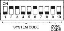
Figure 4.10 Block of ten miniature switches built into each wireless sensor used in a low-cost wireless burglar alarm, to match the sensor’s Tx ‘system’ and ‘zone’ coding to that used in the control unit’s wireless Rx section
Note that, in wireless systems, the main control unit identifies individual sensors purely by their zone codes. Thus, if a sensor in (say) Zone 3 transmits a low-battery-voltape warning, the unit’s control panel will display the fact; if only one sensor carries the Zone 3 code, the owner can quickly identify this particular unit and change its battery, but if several sensors carry the same code the fault can only be traced by individually testing all of the Zone 3 sensor batteries.
Also note that wireless ‘contact’ sensors usually activate only when an n.c. input switch opens for a period of at least 200mS (this technique minimizing the chances of false alarming due to transient switching or signal pick-up); such sensors can be used with any desired number of n.c. sensor switches (reed-and-magnet switches, window foil, etc.) that are loop wired in the basic manner shown in Figure 4.11; they cannot be directly used with pressure mat switches, which are n.o. devices.
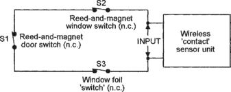
Figure 4.11 Example of three n.c. sensor switches loop-wired to the input of a single wireless ‘contact’ sensor unit
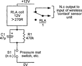
Figure 4.12 shows a simple relay-based adaptor circuit that can be used to activate a wireless contact sensor unit via a pressure mat switch or any other n.o. type of switch (or by any desired number of parallel-connected n.o. switches). Here, 12V relay RLA has a coil resistance of at least 270R, and has one set of change-over (c.o.) contacts that have their n.c pins wired to the input of the wireless sensor unit. RLA’s coil is wired in series with the 12V supply via mat switch S1 and the parallel C1-R1 combination. Normally, S1 is open, C1 is fully discharged, and the RLA/1 output contacts are closed. If S1 now closes, a heavy pulse of current flows through RLA coil via C1 and S1, thus opening the RLA/1 output contact and activating the wireless contact sensor unit. If S1 remains closed, the RLA current rapidly decays to a very low value (determined by R1) and (after a few hundred milliseconds) the RLA/1 contacts re-open; when S1 opens again, C1 slowly discharges via R1 until – after a delay of a minute or so – the system can again be reactivated by closing S1. This circuit thus draws zero quiescent current, and draws only a few microamps of mean current if S1 is closed for long periods.
Wireless alarm system categories
Domestic wireless burglar alarm systems vary greatly in price and performance, but can be roughly divided into the categories of ‘low-cost’, ‘mid-range’, and ‘top-of-the-range’ types. Figures 4.13 to 4.15 illustrate the basic features of typical examples of each of these system types.

Figure 4.13 Block diagram showing the basic features of a typical ‘low-cost’ wireless burglar alarm system
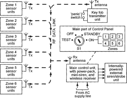
Figure 4.14 Block diagram showing the basic features of a typical ‘mid-range’ wireless burglar alarm system
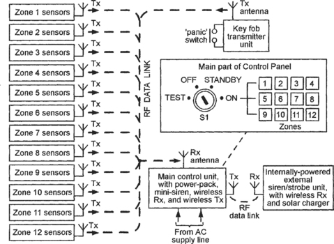
Figure 4.15 Block diagram showing the basic features of a typical ‘top-of-the-range’ wireless burglar alarm system
The cheapest and most popular types of wireless burglar alarm system are those that give levels of protection that are quite adequate for use in small flats or apartments, but give only very basic protection when used in 2 or 3 bedroom houses. Figure 4.13 illustrates, in block diagram form, the basic features of a typical low-cost system of this type. This system offers a total of four defence zones, but these are not individually selectable; in the unit shown, the user has the simple option of making either all four zones active (when the premises are empty), or of making all but one zone (Zone 4, the sleeping and bathroom areas) active (when the occupants are resting); the system gives no protection against burglars who enter the house while the occupants are watching TV, etc. Systems of this type rely on the control unit’s built-in siren to scare off any intruders; often, they are not supplied with an external siren but have provision for driving an optional external siren that is powered by the control unit; such sirens can be disabled by simply cutting their feed cables.
Figure 4.14 illustrates the basic features of a typical ‘mid-range’ wireless burglar alarm system that is designed for use in most houses and in small commercial premises. This system offers a total of six defence zones, all of which are individually selectable, and offers good protection against all types of burglar, including those who enter the house while the occupants are watching TV, etc. Systems of this type are usually supplied complete with an internally-powered external siren/strobe unit that is cable-wired to the main control unit and is fully protected against tampering and cable-cutting, etc.
Finally, Figure 4.15 illustrates the basic features of a typical ‘top-of-the-range’ wireless burglar alarm system that is designed for use in large houses or medium-sized commercial premises. This system offers a total of twelve defence zones, all of which are individually selectable, and offers excellent overall protection. The system shown is completely wireless, with no cable link between the main control unit and the external siren/strobe unit, which is wireless-activated (by the control unit), is fully protected against tampering, and is powered by an internal battery that is trickle charged by an integral solar panel.
Intrusion sensor types
The two types of intrusion sensor most widely used in modern domestic burglar alarm systems are PIR movement detectors for ‘area’ protection, and reed-and-magnet switches for ‘spot’ protection on doors and windows, etc. Other types of sensor commonly used in domestic systems are pressure mat switches for spot ‘floor’ protection, vibration sensors to give ‘object’ protection, and window foil and glass break detectors to detect window breakage. All of these sensors are similarly used in burglar alarm systems designed to protect commercial premises, which sometimes also use IR light beams or brittle wires (built into walls, floors, or ceilings) to detect break-ins via the building’s shell.
Note that modern PIR movement detectors are relatively inexpensive and have a high immunity to false alarms, and have consequently replaced once-popular but unreliable capacitive proximity detectors and microwave and ultrasonic movement detectors in most modern commercial ‘area’ protection systems. Older readers may also note that once-popular ‘dual-purpose loop’ burglar alarm systems – in which all contact sensors are wired to a continuously-monitored loop that is fitted with an end-of-line resistor – are no longer used in the modern domestic security systems.
Practical burglar alarm circuits
Modern microcontroller-based domestic burglar alarm systems are, like TVs and many other electronic ‘consumer’ products, so reasonably priced that few people would seriously consider DIY-building – rather than buying – such products. This is particularly true of wireless burglar alarm systems, which must use wireless Tx sections that have passed stringent tests laid down by a government testing/licensing authority. It is, however, possible to cost-effectively DIY-build a variety of fairly simple and inexpensive ‘conventional’ burglar alarm and accessory circuits, and a number of these are described in the remaining sections of this chapter.
A ‘false key’ booby trap circuit
Some people hide a spare front door key under a flower pot or porch mat or on a porch ledge when they leave the house, and burglars often make a quick search for such a key when they enter the porch area of a house. ‘False key’ booby trap units take advantage of this fact by activating a semi-latching siren if an object such as a flower pot is briefly moved, or if someone grabs a key that is tied to a short length of string, etc. Figure 4.16 shows the practical circuit of such a unit.
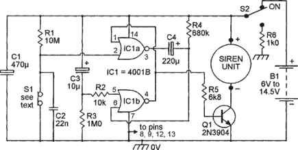
In Figure 4.16, two gates of the 4001B CMOS IC are wired as a simple monostable multivibrator that gives a low pin-4 output when a positive voltage is fed to pin-5, but, if pin-5 is low, produces a positive pin-4 output pulse if a positive-going transition is applied to pin-2 by opening sensor switch S1; this output pulse has a duration of about 2 minutes with the R4–C4 values shown, and is used to activate an inexpensive commercial siren unit via R5 and transistor Q1. Note that the monostable can only be triggered by a positive-going transition of its pin-2 voltage; its action is not influenced by ‘standing’ high or low voltages applied to pin-2 via R1–S1. Thus, the action of this booby trap circuit – which may typically be housed in an inverted flower pot – is as follows:
When power is switched to the circuit via S2, C3–R3 apply a decaying positive voltage to pin-5 that disables the monostable for at least 12 seconds, thus giving the user time to safely ‘prime’ the circuit (position it so that S1 is held in the closed position) without activating the siren. At the end of this period the monostable becomes enabled; if sensor switch S1 subsequently opens for a period in excess of 200mS (determined by R1–C2), the monostable fires and activates the siren for a continuous period of about 2 minutes (which is long enough to scare off most burglars). At the end of this 2-minute period the siren turns off, irrespective of the state of S1, and can only be retriggered by closing and then opening S1 again. Note that R6 discharges the circuit’s timing capacitors when control switch S2 is turned off, that most of the unit’s circuitry must be weatherproofed and protected with varnish, and that the unit can be powered by any 6V to 14.5V battery supply and the unit consumes a quiescent current of only a few μA (mainly via R1 and via C1’s leakage currents),
The circuit’s S1 sensor switch can take various forms; in a flower pot unit it may be an n.o. key-pad switch that is normally held closed by the weight of the pot, but opens when the pot is lifted; in another case it may be an n.c. type that opens when someone tugs on a piece of string, and so on.
Shed/garage burglar alarm circuits
Domestic workshops and garages that are fitted with AC power lines are best defended by simple AC-powered ‘house/flat’ types of burglar alarm that can activate powerful siren/light-strobe units for several minutes, and a versatile alarm unit of this type is shown later in this chapter. Most garden sheds and many domestic garages (and also caravans and small boats, etc.) are, however, devoid of AC power lines, and are best defended by battery-powered burglar alarms that, when activated, sound a siren for only a few minutes; this section looks at some practical circuits of this type.
Figures 4.17 to 4.20 show alternative versions of battery-powered shed/garage burglar alarms, which should ideally be powered by rechargeable batteries that are kept fully energized by solar-powered charger units. The Figure 4.17 – 4.18 unit is meant to be turned on and off by a key-switch that is operated from outside the building; the Figure 4.19 – 4.20 unit is meant to be turned on and off from within the building, and incorporates exit/entry time delays that let the key holder leave and enter the building without sounding its alarms. Each burglar alarm unit consumes a typical ON (‘standby’) current of 1-2μA, can use any desired number of n.o. (S1) and/or n.c. (S2) sensor switches, and has a pair of c.o. relay output contacts that latch on for about 5 minutes under the ‘alarm’ condition and can be used to activate any type of external siren, which may be self-powered or may be powered from the burglar alarm’s battery via the relay contacts.


Figure 4.18 Optional state-indicating sounder, for use with the Figure 4.17 circuit
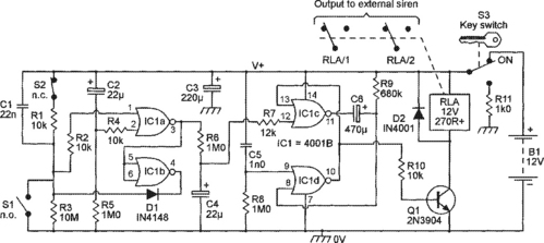
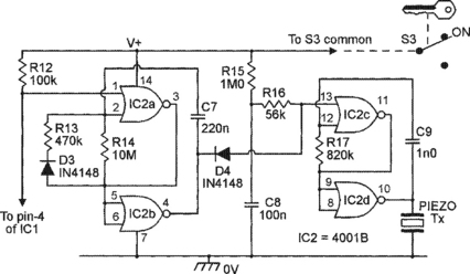
Figure 4.20 State-indicating sounder, for use with the Figure 4.19 circuit
Note in the Figure 4.17 and 4.19 diagrams that S1 can consist of any desired number of n.o. switches (including ‘tilt’ switches of the type used on up-and-over types of garage door) wired in parallel, and S2 can consist of any desired number of n.c. switches (such as reed-and-magnet switches on shed doors and opening windows, anti-tamper switches built into alarm and siren boxes, wire ‘loops’ formed inside easily-cut cables, and cable loops used to protect tools, etc.) all wired in series; if S1 is not needed, simply omit it; if S2 is not needed, replace it with a short.
The Figure 4.17 burglar alarm circuit is turned on and off via key-operated switch S3, which is mounted in a position where it can be operated from outside of the building’s main entrance; thus, S3 is used to enable the alarm after leaving the building, and to disable it before entering the building. The circuit is basically similar to that of Figure 4.16, which uses two gates of a 4001B IC as a triggered monostable pulse generator. In this case, however, the monostable output has a period of about 5 minutes and activates relay RLA via transistor Q1, and can be triggered by closing n.o. switch S1 or by opening n.c. switch S2.
Figure 4.18 shows an optional audible-output ‘system-state’ indicator that can be added to the Figure 4.17 alarm circuit and emits a brief ‘bleep’ when the alarm circuit is first switched on, confirming that it is receiving power, and emits a longer ‘decaying’ bleep as the alarm circuit is switched off, confirming that its power has been removed (if you do not use this add-on circuit, change the R7 value to 1k0 and wire its low end to the 0V line). In Figure 4.18, IC2 is wired as a gated astable that – when gated on by a ‘low’ voltage on pin-1 – generates an audible tone signal in a low-cost piezo sounder. The action is such that the astable is briefly driven on via R8–C5 as S3 is switched to the ON position, thus generating a brief ‘bleep’ in the sounder; when S3 is switched to the OFF position, C1’s stored charge drives the astable on via R7-Q1 and supplies the astable with limited operating power, thus producing a decaying ‘bleep’ in the sounder.
The Figure 4.19 burglar alarm circuit is turned on and off via key-operated switch S3, which is mounted inside the shed/garage; when S3 is first turned ON, an ‘exit delay’ comes into operation, giving the key holder about 18 seconds to leave the building, after which all S1/S2 sensor switches become fully active; when the building is re-entered after this period, the sensor switches trigger an ‘entry delay’ timer that – if S3 is not switched OFF within 18 seconds – triggers a 5-minute monostable that drives an external siren via the contacts of relay RLA. The basic circuit is similar to that of Figure 4.17, except that exit/entry time-delay logic is interposed between the outputs of S1/S2 and the input trigger point of the 5-minute monostable pulse generator (IC1c–IC1d). The circuit operates as follows:
In Figure 4.19, IC1a is used as a NOR gate that gives a low (logic-0) pin-3 output if either input is high, and gives a high output only if both inputs are low. The pin-1 input of IC1a is normally high, but goes low if S1 closes or S2 opens; the pin-2 input of IC1a is normally low, but is held high by the C2–R5 ‘exit delay’ network for about 18 seconds when power is first applied to the circuit via S3. Thus, IC1a’s output is locked low during the ‘exit delay’ period, but can subsequently switch high if S1 closes or S2 opens; if this latter action occurs, the output of inverter IC1b pulls IC1a’s pin-1 input low via D1, thus locking its output into the high state, irrespective of subsequent S1/S2 actions. This ‘high’ output is fed to the pin-12 ‘trigger’ input pin of the IC1c–IC1d relay-driving 5-minute monostable via the R6–C4 ‘entry delay’ timing network, which triggers the monostable about 18 seconds after pin-3 goes high.
Figure 4.20 shows an optional audible-output ‘system-state’ indicator that can be added to the Figure 4.19 alarm circuit and emits a brief ‘bleep’ when the alarm circuit is first switched on prior to leaving the building, and emits a series of 50mS ‘bleeps’ at roughly 1-second intervals when anyone re-enters the building, reminding them to turn S3 OFF before the siren-activating finish of the ‘entry delay’ period. In Figure 4.20, IC2c–IC2d are wired as a gated astable that – when gated on by a ‘low’ voltage on pin-13 – generates an audible tone signal in a low-cost piezo sounder, and IC2a–IC2b are wired as a gated asymmetrical astable that gates the IC2c–IC2d astable via D4 and activates automatically when anyone re-enters the building. The action is such that the IC2c–IC2d astable is briefly driven on via R15–C8 as S3 is switched to the ON position, thus generating a brief ‘bleep’ in the sounder, and is activated via the IC2a–IC2b astable whenever the main unit’s ‘entry delay’ circuitry becomes active, thus generating a series of 50mS ‘bleeps’ that are repeated at 1-second intervals until the main alarm unit is turned off via S3.
House/flat burglar alarm circuits
Shed/garage burglar alarms of the Figure 4.17 to 4.20 types are simple battery-powered single-zone units. Modern burglar alarms suitable for use in houses, flats and apartments are moderately complex AC-powered multi-zone units with built-in ‘panic’ and ‘tamper’ facilities; they usually have an internal trickle-charged battery that provides power in the event of an AC power-line failure, and have auxiliary 12V DC outputs suitable for powering external PIR movement detectors, etc. Figures 4.21 to 4.25 show the block diagram and practical circuit details of a sophisticated modular ‘universal’ burglar alarm unit of the latter type that can easily be built to suit the precise needs of the individual user.


Figure 4.21 shows the basic block diagram of the ‘universal’ burglar alarm unit, which can be fitted with one exit/entry zone plus any desired number of ‘normal’ defence zones, all of which are individually switch-selectable; each zone is provided with its own audio/visual ‘state’ indicator (not shown in this diagram) and activates internal and external alarm sirens when an intrusion is detected. The unit can also be fitted with any desired number of n.c. ‘panic’ switches (S3) wired in series, and with any number of n.c. tamper switches or loops (S2) wired in series. The unit comprises the four major sections shown in the diagram, and offers the following modes of operation, which are selectable via 4-way key-operated switch S1:
ON. When S1 is in the ON position, all four major sections of the unit are energized, and the ‘alarm timing/control’ circuitry’s 50-second and 16-minute timers are immediately triggered if an intrusion is detected by the ‘alarm triggering’ circuitry or if PANIC switch S3 is opened for more than 200mS. Under this condition the internal siren is immediately driven on via D4 and Q4, but the external siren (which is activated via 02 and RLA) is held off for 50-seconds via R4–Q1, thus minimizing the chances of accidentally sounding the external alarm; both alarms switch off when S1 is moved to the RESET position, or turn off automatically at the end of the 16-minute timing period; the intrusion detector’s piezo buzzer also sounds if an intrusion is detected and operates for the duration of the intrusion condition. The internal siren is driven on (via D5) if TAMPER switch S2 opens, and sounds for the duration of the open circuit condition.
TEST. When S1 is in the TEST position, the ‘alarm timing/control’ circuitry and the TAMPER and PANIC switches are disabled, but the intrusion detection circuitry is fully active; if an intrusion state is detected under this condition, only the internal piezo buzzer is activated. This mode is useful when testing or checking sensor switches, PIR units, or sensor wiring, etc.
OFF. When S1 is in the OFF position, the intrusion detection circuitry is disabled, but the TAMPER and PANIC circuitry is fully active. If TAMPER switch S2 opens, the internal siren is driven on (via D5–Q4) for the duration of the open circuit condition. If PANIC switch S3 opens, the internal siren is driven on immediately (via D4–Q4) and the external siren activates 50-seconds later; both sirens turn off when S1 is moved to RESET, or turn off automatically at the end of the 16-minute timing period.
RESET. When S1 is in the RESET position, the entire circuit (except the power supply circuitry) is effectively disabled, and Q3 rapidly resets the intrusion detector circuit’s ‘exit delay’ timer.
Figure 4.22 shows the basic circuitry of the ‘universal’ alarm unit’s intrusion sensing/signal processing circuitry, specifically applied to a unit with one entry/exit zone (Zone ‘A’) and three ‘normal’ zones (Zones ‘B’ to ‘D’); additional ‘normal’ zones can be added by simply duplicating the Zone ‘D’ and D5 circuitry for each extra zone. All zones use the same intrusion sensing circuit design as shown for Zone ‘A’. Each zone can use any desired number of series-connected n.c, (SWa) and/or parallel-connected n.o. (SWb) sensor switches, and is selected by a DPDT switch (SWc) that, when closed, connects the output of inverting buffer IC1a to a state-indicating LED (LED1a) and also connects the +12V supply to any auxiliary units (PIRs, etc.) that are associated with the zone. When a zone is selected by SWc and key-switch S1, its action is such that the output of IC1a goes high and illuminates the LED and activates a piezo buzzer (via D1 or D2) if any of the zone’s intrusion-detecting sensor switches are activated; this ‘high’ signal is also passed through the unit’s signal processing circuitry, as described in the next two paragraphs.
In Figure 4.22, the output signals from the sensing circuits of all selected ‘normal’ defence zones are ORed via D3–D4–D5 and are then fed to input A (monotone sound) of the piezo buzzer via D2, and also through transient suppressor R10–C3 (which only passes signals that switch high for at least 200mS); the output of R10–C3 is then inverted by IC3a and passed to one input of NOR-gate IC3c, which has its other input derived from 30-second switch-on delay generator R13–C4–IC3b, which disables IC3c for 30 seconds when power is first connected to the circuit via S1. The net result is that the circuit gives an instant audio-visual indication if the output of any selected zone switches high, but under this condition IC3b’s output only generates a siren-activating signal (via D8) if the circuitry has been energized via S1 for at least 30-seconds.
In Figure 4.22, the output signals from the entry/exit zone are (when SWc is closed) fed to input A of the piezo buzzer via D1, and also passed – via transient suppressor R5–C1 – to the input of a gated self-latching non-inverting buffer formed by 1C2a–IC2b, which is gated by the R13–C4–IC3b 30-second switch-on delay generator, which provides the zone with its ‘exit’ delay. If the zone’s output switches high during the 30-second exit delay period (as, for example, when someone exits the zone), the circuit gives an instant audio-visual indication of the fact but produces no other effects. If the zone’s output switches high after the end of the 30-second exit delay period (as, for example, when someone re-enters the zone), the circuit again gives an instant audio-visual indication of the fact, but in this case the output of IC2b switches high and is latched into that state via D6–R7; this action drives input B (timing-beat sound) of the piezo buzzer high and also initiates a 30-second entry delay timing period (controlled via R8–C2 and non-inverting buffer IC2c–IC2d); if the complete circuit is not switched off (via S1) by the end of this 30-second ‘entry’ period, IC2d’s output switches high and activates the unit’s sirens via D7.
Note in Figure 4.22 that D9–R14 are used to rapidly discharge C4 via the positive supply rail and Figure 4.21‘s transistor Q3 when S1 is moved to the RESET position. Also note, when building the Figure 4.22 circuit, that pin-14 of all 4001B ICs must be wired to the +ve supply rail, pin-7 to the 0V rail, and that all unused gate input pins must be tied to the 0V rail. All LEDs must be high-brightness types.
Figure 4.23 shows the circuit of the unit’s state-indicating piezo buzzer unit, which is powered from the supply rails of the intrusion sensing/signal processing circuitry and consists of two gated astables that are activated by high (logic-1) gate voltages. IC1c–IC1d are wired as a simple ‘tone’ astable that – when gated on via pin-13 – generates a 680Hz tone signal in the piezo sounder, and IC1a–IC1b are wired as a gated semi-latching asymmetrical astable that – when gated on via the alarm’s ‘entry delay’ timer (see Figure 4.22) – produces one-per-second 50mS output pulses that gate the tone astable via D2. The action is such that the tone astable is briefly driven on via C2–R6 when power is first switched to the circuit, thus generating a brief ‘switch-on’ bleep in the sounder, and is activated via the input-‘A’ terminal whenever a sensor switch is activated in any of the alarm’s active zone areas. The tone astable is also activated via the IC1a–IC1b astable and D2 whenever the alarm’s ‘entry delay’ circuitry becomes active, thus generating a series of 50mS ‘bleeps’ at roughly 1-second intervals when anyone re-enters the building, reminding them to tum key-switch S1 OFF before the siren-activating finish of the ‘entry delay’ period.
Figure 4.24 shows the circuit of the alarm’s siren control unit, which is based on the block diagram of Figure 4.21 but uses its own component numbering system and is energized when S1 is in the ON and OFF positions. Here, IC1a–IC1b are wired as a non-inverting buffer that drives the internal siren on (via D1–Q3) if Tamper switch S2 opens, and the remaining ICs act as triggered 50-second and 16-minute timers that activate the internal and external sirens if Panic switch S3 is opened or if a ‘high’ input is received from the output of the alarm’s intrusion detector circuitry. These timing circuits operate as follows:
In Figure 4.24, IC1c–IC1d are wired as a simple monostable timer that controls the external siren’s ‘hold-off’ period; it is automatically reset at S1-switch-on via C3–R5 and is triggered by a positive-going transition on pin-12 (derived from the intrusion detector, or by opening S3). When triggered, the monostable’s pin-10 output switches high and activates the IC2–IC3 16-minute timer and turns Q1 on, but switches low again at the end of its 50-second (nominal) timing period, which is controlled by R6–C4. In practice, this timing period also depends on the ‘threshold’ voltage value of the individual IC, and may vary substantially from the 50-second value; if it does, make the timing roughly correct by changing the R6 value.
The output of the 50-second timer triggers the 16-minute timer, which is a semi-precision design built around a bistable latch (IC2a–IC2b), a gated 8.5Hz astable (IC2c–IC2d), and a 14-stage (divide-by-16 384) ripple counter (IC3). The action is such that, at switch-on, the bistable is automatically reset (with its pin-3 output low and pin-4 high) via C3–R5–R7, thus gating the astable off, and the counter is reset via C6–R9. As soon as the 50-second timer (IC1c–IC1d) is triggered, its pin-10 output flips the IC2a–IC2b bistable, driving the internal siren on via D2–Q3 and feeding a drive current towards the base of relay-driving transistor Q2 via R12–R11, and also gating on the astable, which immediately starts feeding clock pulses into the IC3 counter at a 8.5Hz rate.
Note that, in the early stages of this 16-minute timing sequence, Q1 is driven on by the monostable timer, thus preventing the bistable’s drive current from reaching the base of Q2, but that Q1 turns off after 50 seconds, thus enabling Q2 to turn on and activate the external siren via relay contacts RLA/1–RLA/2. Meanwhile, the astable keeps feeding clock pulses into the counter until, after 16-minutes, on the arrival of the 8192nd pulse, the pin-3 output flips high and resets the bistable via D3, thus terminating the timing process and turning both the internal and external sirens off. The circuits timing period can easily be set to precisely 16-minutes by connecting a LED and 4k7 series resistor between pins 12 and 8 of IC3 and – with the timer triggered – carefully trimming RV1 so that the LED operates with precise 30-second on and off periods.
Figure 4.25 shows the circuit of the alarm’s ‘reset’ and internal siren driver circuitry, together with its connections to S1; this diagram is based on those of Figures 4.21 and 4.24 but uses its own component numbering system. Here, Q1 is driven on whenever S1 is in the RESET position, and rapidly resets the alarm’s intrusion detector ‘exit delay’ timer by discharging its timing capacitor (C4 in Figure 4.22). Q2 is driven on (via the output of the alarm timing/control unit) and activates the internal siren unit (a low-cost multi-tone medium-power commercial unit) whenever an intrusion is detected or a tamper or panic switch is operated; the specified Q2 transistor has a maximum current rating of 200mA, which is adequate for driving most medium-power 12V sirens.
Regarding the ‘universal’ burglar alarm’s power supply, note that the basic unit consumes a typical standby current of only a few microamps and can, if desired, simply be powered by a rechargeable 12V battery. In practice, however, modern burglar alarms are usually used in conjunction with PIR detector units, each of which typically consume a quiescent current of 20mA; thus, a system that uses three PIRs consumes a quiescent operating current of about 60mA, which can – if desired – be supplied by a 12V rechargeable 1.2AH battery that is fed – via a protective diode – via the output current of a line-powered 60mA trickle charger. In a unit of this type, the charger supplies the full operating current when the alarm is in its ON but untriggered mode; the battery supplies all excess power if the alarm is triggered, and receives a safe 60mA (l/20th of its 1.2AH capacity) trickle charge when the alarm is not in the ON state.
Finally, note that the ‘universal’ burglar alarm is very simple to operate, and is normally used in the ON mode when required to respond to an intrusion, and in the OFF mode (in which its panic and tamper switches are still active) when it is not required to detect an intrusion. The TEST mode is only used when setting up or testing the system. The RESET mode is only used to reset the alarm timing/control circuitry once an alarm siren has activated, or to rapidly reset the intrusion detector’s exit delay timer when an unexpected repeat of the full ‘exit delay’ time is needed.