
Automobile security circuits
Modern automobiles virtually bristle with various ‘security’ devices and gadgets, which are designed to enhance the vehicle’s safety, reliability, mechanical efficiency, and immunity to theft. If you own a reasonably modern (post 1994) automobile, it is probably already so well equipped with good security devices that you will not need to add any more. If, on the other hand, your vehicle dates back well beyond 1989, you may be able to gain by fitting one or more of the simple security circuits that are described in this chapter, or by using one or more of the various commercial ‘add-on’ vehicle security units that are widely available.
To help illustrate some of the advances that have taken place in automobile security in recent years, let me cite two of my own personal experiences. At the time of writing (1998) I own a perfectly standard 1995, bottom-of-the-range, European-built 4-door family saloon, and before that I owned a 1986 version of the same basic vehicle. The 1986 vehicle was (as supplied from the factory) fitted with no anti-theft devices other than simple key-controlled door, steering and ignition locks, had a traditional petrol engine that used a normal carburettor and had a manual choke, and had 2-speed windshield wipers but was otherwise completely devoid of modern ‘security/safety’ devices.
By contrast, my 1995 vehicle is fitted – as standard equipment – with a central-locking system that controls the security of its four doors and can be activated manually or via an infra-red remote-control key-fob, is fitted with three different anti-theft systems, has a smart electronically-controlled fuel-injection petrol engine with an automatic choke, has multi-speed windshield wipers, has a timed auto-turn-off rear-screen heater, and has a ‘lights-are-on’ reminder that automatically activates a bleeper if I try to leave the vehicle while its lights are still turned on.
My 1995 vehicle’s three anti-theft systems are additional to its normal key-controlled door, steering and ignition locks, and consist of a basic switch-activated alarm unit that activates if any of the vehicle’s doors or its trunk (boot) or bonnet (hood) are illegally opened, plus a dual narrow-beam short-range ultrasonic unit that triggers an alarm if anyone pushes an arm through either of the two front-side windows while the alarm is turned on, plus a key-pad engine immobilizer that only enables the electronically-controlled fuel-injection system if the correct ignition key is used and a personal 4-digit code is punched into the key-pad before trying to start the engine.
This chapter presents a variety of automobile add-on security circuits that are particularly suitable for use in most older vehicles that are fitted with 12V electrical systems. Its main section starts by describing vehicle anti-theft principles, then presents a few simple but useful anti-theft circuits, and then goes on to describe various simple circuits that can be used to enhance a vehicles safety or reliability.
Vehicle anti-theft principles
Vehicle thieves come in three basic types, and can be categorized as either car burglars, drive-away thieves, or hoist-away thieves. Car burglars are mainly interested in stealing saleable articles from vehicles; usually, they enter the vehicle by smashing a side window and then opening the side door and grabbing any valuables that are lying around; they work fast, do expensive damage to the vehicle, and are not usually deterred by burglar alarms. Some car burglars specialize in stealing vehicle parts such as wheels (and their easily-sold tyres) and radios. It is almost impossible to protect modern vehicles against really determined car burglars.
Drive-away thieves simply break into the vehicle and drive it away for temporary pleasure or for use in some criminal enterprise or for resale in either complete or broken-down form. Most drive-away thieves can be deterred by a well-designed burglar alarm and a good and sensible-fitted immobilizer unit.
Hoist-away thieves steal a complete vehicle by either towing it away or hoisting it onto the back of a truck; the vehicle is then (usually) deposited in an enclosed workshop, where it is processed ready for resale through a local, national, or international dealing organization. Most hoist-away thieves only steal vehicles with a good resale value, and are rarely detected by burglar alarms or inconvenienced by immobilizers. Vehicles can be given fairly good protection against this type of theft only by fitting the vehicle with a modern (and expensive) wireless ‘tracker’ system, as described in the next section of this chapter.
Anti-theft devices
Vehicle anti-theft devices come in four basic types. The first and simplest of these are mechanical ‘theft’ deterrents such as steering locks and lockable filler caps and wheel nuts, etc. Note that most built-in steering locks (of the type that are operated via the vehicles ignition key) are fairly weak, and can often be broken by an experienced car thief – using brute force – in just a few seconds. Add-on steering locks are usually very strong and are excellent deterrents against drive-away car thieves, but are cumbersome to use.
The second type of anti-theft device is the ‘immobilizer’, which is intended purely to reduce a thief’s chances of starting or driving away a target vehicle; it offers no protection against the car burglar or against haul-away thieves. Immobilizers usually consist of some type of electronic or electromechanical ‘switch’ that is wired into some part of the electrical wiring of the vehicles engine, so that the engine will only operate if the ‘switch’ is disabled.
The third type of anti-theft device is the true burglar alarm, which sounds an alarm (and perhaps also immobilizes the vehicle’s engine) if any unauthorized person tampers with the vehicle or tries to force their way into it. These alarms may be activated in any of several basic ways. The most popular way is via microswitches that operate when any of the car doors, hood or trunk are opened. Microswitch-activated alarms are fairly inexpensive, very reliable, and give excellent anti-theft protection.
Another way of detecting an intrusion is via the small volt drop that takes place across the vehicle’s battery when a door-, hood- or trunk-activated courtesy light turns on, or when the ignition is turned on. These so-called ‘voltage sensing’ alarms give the same degree of anti-theft protection as the microswitch types of alarm system, but are generally more expensive and less reliable.
Some vehicle alarms are activated by a vibration or movement detector, which reacts when a vehicle is entered or moved. Most of these systems have poor reliability, and can be false-triggered by natural movements caused by vehicles passing close by, or by strong gusts of wind, or by potential thieves deliberately rocking the vehicle in an effort to destroy the owner’s trust in the system.
Some vehicle alarms are ultrasonic ‘doppler shift’ types, in which an ultrasonic transmitter (Tx) and a matching receiver (Rx) are aimed into the vehicle’s driver/passenger compartment. If anyone enters any part of the compartment they cause a doppler shift in the Rx signal, and this activates the alarm. In practice, similar doppler shifts can be caused by draughts blowing through poorly closed windows or ventilators, and many such units thus have very poor reliability. In most modern vehicles, ultrasonic units are only used to give short-range protection of small areas, such as front-side windows, and are used in conjunction with conventional microswitch-types of alarm unit, rather than as stand-alone alarms.
Practical vehicle burglar alarm systems may be designed to be switched on and off either from within the vehicle, or from outside. Up until the late 1980s, most vehicle burglar alarm systems were switched from within the vehicle. Internally switched burglar alarms must incorporate exit and entry delays of about 20 seconds, to enable the owner to leave or enter the vehicle without sounding the alarm. This entry delay makes the vehicle very vulnerable to car burglars, who can easily carry out a snatch-theft in less than 20 seconds and thus escape before the vehicle’s alarm sounds.
By contrast, externally switched vehicle burglar alarms sound off the instant that any car door starts to open, and thus give better protection against car burglars. Most modern cars are fitted with a central-locking system that protects all doors, and this system and the burglar alarm are controlled (turned on and off) externally via the driver’s door key or via a wireless or IR remote-control key-fob. If you want to give this kind of protection to an older vehicle you can do so by buying a fit-it-yourself central locking system and remote-controlled burglar alarm, etc., from a specialist dealer.
A cheaper way of fitting an externally switched burglar alarm to an older vehicle is to simply fit microswitches to all car doors and to the hood and trunk, to use these to activate one of the simple anti-theft alarms described later in this chapter, and to turn the alarm on and off via a hidden toggle-switch or a prominent key-switch that is fitted to the outside of the vehicle.
The fourth and final type of vehicle anti-theft device is the wireless ‘tracker’ system, which is meant to be used in conjunction with a normal burglar alarm/immobilizer system and is used solely to quickly (often in less than half an hour) help track down the vehicle if it is stolen, even if it is hidden away in an enclosed workshop. A ‘tracker’ is a special wireless receiver/transmitter unit that normally lies dormant, hidden away in the vehicle. If the vehicle’s owner reports the vehicle’s theft to the police (or some other law-enforcement authority), they will wireless-transmit that vehicle’s special ‘tracker’ code number which – if received – will activate the tracker’s transmitter, thus enabling the vehicle to be quickly found with the aid of suitable wireless-location equipment.
The comparative table of Figure 7.1 shows the degree of protection that different types of vehicle anti-theft device offer against different types of thief. Thus, immobilizers give good protection against drive-away thieves but give no protection against car burglars or hoist-away thieves, while externally switched microswitch-activated and voltage-sensing alarms give good protection against all except hoist-away thieves.

Practical immobilizer circuits
An immobilizer can greatly reduce a thief’s chances of starting or driving away a target vehicle. Simple immobilizers can take the form of a secret switch (or a pair of remotely-controlled relay contacts) wired into some vital electrical part of the vehicle’s engine; Figures 7.2 to 7.5 show some basic circuits of this type.
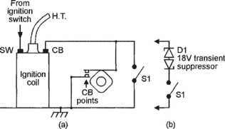
Figure 7.2 Contact-breaker immobilizer, operates when switch is closed; (a) is basic circuit, (b) is improved circuit
Figures 7.2 and 7.3 show how immobilizers can be wired into the engine’s ignition system. In Figure 7.2(a), switch S1 is wired across the engine’s contact-breaker (CB) points; when S1 is open the ignition operates normally, but when it is closed the CB points are shorted out and the engine is unable to operate. This simple circuit gives excellent protection, particularly if the wiring is carefully concealed at the CB end, but S1 must be able to handle the coil’s high operating current when it is closed, and be able to withstand the CB point’s typical 600V peak-to-peak ‘ringing’ voltages when the engine is operating normally.
The improved immobilizer circuit of Figure 7.2(b) does not suffer from the above snags. Here, an inexpensive and easily available 18V transient suppressor diode (D1) – which acts like a pair of back-to-back Zeners – is wired in series with S1; this device passes no current until its applied voltage exceeds 18V, and acts like a near-short to voltages greater than 18V. Thus, in this circuit, S1 passes zero DC current when it is closed, but kills the ignition systems vital ‘ringing’ voltages when an attempt is made to start the engine. This circuit gives superb anti-theft protection.
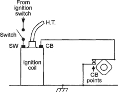
In the Figure 7.3 circuit the immobilizer switch is wired in series with the vehicle’s ignition switch, so that the engine operates only when the switch is closed. The protection offered by this circuit is not quite as good as that of Figure 7.2, since a moderately skilled thief can easily by-pass the immobilizer and ignition switches by simply hooking a wire from the battery to the SW terminal of the ignition coil.
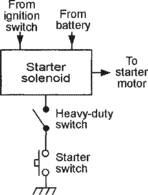
Figure 7.4 shows how a heavy-duty immobilizer switch can be wired into the vehicle’s electric starter system, so that the starter only operates if this switch is closed. This system gives better protection than that of Figure 7.3, but is not as good as Figure 7.2 because the starter solenoid can be operated manually on many old vehicles, and also because the starter and immobilizer switches can be by-passed by a single length of wire.
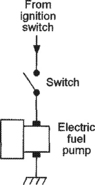
Finally, Figure 7.5 shows how an immobilizer switch can be wired in series with the electric fuel pump on suitable vehicles, so that the pump only operates when this switch is closed. Note that this system lets a thief start the engine and drive for a short distance on the carburettor’s residual fuel, which is quickly used up.
A weakness of the Figure 7.2 to 7.5 circuits is that they must all be turned on and off manually, and thus only give protection if the owner remembers to turn them on. By contrast, Figure 7.6 shows an immobilizer that turns on automatically when an attempt is made to start the engine, but can be turned off by briefly operating a hidden push-button switch. A small ‘reminder’ light turns on when the engine is disabled by the immobilizer. This circuit thus gives a high level of protection, since it does not depend on the memory of its owner, and operates as follows.

The coil of relay RLA is shunted by series-connected R1 and a LED, which illuminates when RLA is on, and this combination is wired in series with 1000μF capacitor C1, which is shunted by series-connected n.o. relay contacts RLA/1 and n.c. push-button switch S1; this RLA–C1 combination is wired between the ignition coil’s SW terminal and ground, and the relay’s RLA/2 n.o. contacts are wired across the vehicle’s CB points.
Normally, C1 is fully discharged; consequently, when the ignition switch is first closed a surge of current flows through RLA coil via C1, and the relay turns on, illuminating the LED. As the relay goes on, contacts RLA/1 close and lock the relay on via S1, and contacts RLA/2 close and short out the vehicle’s CB points, thus immobilizing the engine. The relay stays on until S1 is briefly opened, at which point the relay unlatches and C1 charges up rapidly via the relay coil, and the relay and LED then turn off. As the relay turns off, it removes the short from the vehicles CB points, and the engine is able to operate in the normal way.
The relay used in the Figure 7.6 circuit can be any 12V type with a coil resistance of at least 180R, and with two sets of n.o. contacts. The circuit shown is designed for use on vehicles with normal negative-ground 12V electrical systems; some older vehicles use 12V positive-ground systems, and on these simply reverse the polarities of C1 and the LED.
Anti-theft alarm circuits
It was explained earlier in this chapter that the most reliable vehicle anti-theft alarms are externally switched microswitch-activated or voltage-sensing types, and that on older vehicles these can be inexpensively turned on and off via a prominent key-switch (or a concealed toggle switch) fitted to the outside of the vehicle. Figures 7.7 to 7.14 show practical examples of alarm systems of these types; each of these circuits can also act as an immobilizer, and (if required) operates the vehicle’s horn and lights and immobilises the engine under the ‘alarm’ condition.

Figure 7.7 Basic microswitch-activated anti-theft alarm/immobilizer for 12V negative-ground vehicles

Figure 7.8 Basic microswitch-activated anti-theft alarm/immobilizer for 12V positive-ground vehicles
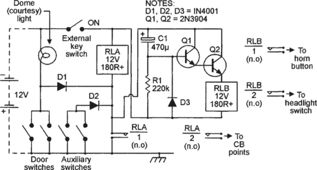
Figure 7.10 Improved anti-theft alarm/immobilizer (for 12V positive-ground vehicles) has time-controlled outputs
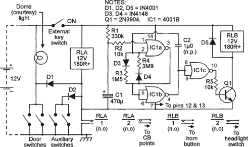
Figure 7.11 Improved anti-theft alarm/immobilizer (for 12V negative-ground vehicles) has pulsed and time-controlled outputs
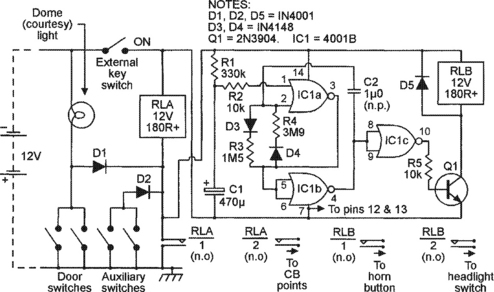
Figure 7.12 Improved anti-theft alarm/immobilizer (for 12V positive-ground vehicles) has pulsed and time-controlled outputs


In the Figure 7.7 to 7.12 circuits, microswitches that are built into the vehicle are used to trip a pair of self-latching relays when any of the car doors, hood or trunk are opened; these relays immobilize the engine and operate the horn and headlights either directly or via additional timing circuitry. Two suitable front-door microswitches are built into most vehicles as standard fittings and are used to operate the courtesy or dome lights; additional dome-light-operating microswitches, which are readily available from specialist ‘vehicle security’ retailers, can easily be fitted to the rear doors. Similar microswitches can be used as ‘auxiliary’ switches to protect the hood and trunk (bonnet and boot).
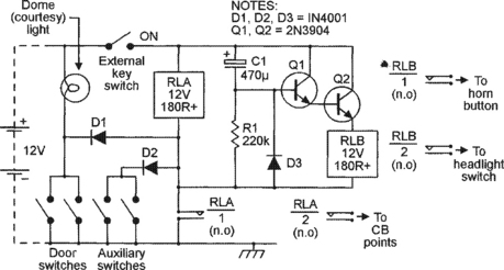
Figure 7.9 improved anti-theft alarm/immobilizer (for 12V negative-ground vehicles) has time-controlled outputs
The operation of the Figure 7.7 circuit is very simple. Normally, with the key-switch open, no voltage is fed to the relay network, so the alarm is off. Suppose, however, that the key-switch is closed. If any of the door switches close, current flows through both relays via D1, or if any of the auxiliary switches close, current flows through both relays via D2. In either case, both relays turn on, As RLA goes on, contacts RLA/1 close and lock both relays on, and contacts RLA/2 close and short out the vehicle’s CB points, thus immobilizing the vehicle.
Simultaneously, contacts RLB/1 close and switch on the car horn (or a siren unit), giving an audible indication of the intrusion, and contacts RLB/2 close and switch on the headlights (or activate a headlight flasher unit), giving a visual identification of the violated vehicle. The horn and light (etc.) remain on until the key-switch is opened.
The Figure 7.7 circuit is meant for use on vehicles fitted with normal 12V negative-ground electrical systems. The circuit can be modified for use on old vehicles fitted with 12V positive-ground systems by simply reversing the polarities of D1 and D2, as shown in Figure 7.8.
Obvious weaknesses of the simple Figure 7.7 and 7.8 circuits are that, if they are activated and are not switched off manually within a reasonable space of time (typically 15 minutes), they will probably break local noise-control regulations, will probably damage the horn, and will eventually flatten the vehicle’s battery. Figure 7.9 shows a way of modifying the Figure 7.7 circuit so that the horn and lights turn off automatically after about four minutes, but the immobilizer stays active until turned off via the key-switch, thus eliminating all of the above problems.
In Figure 7.9, RLA turns on and self-latches in the same way as in the Figure 7.7 circuit, but as contacts RLA/1 close they connect the full battery voltage across the Q1–Q2 RLB-driving timer network, which has its timing controlled via C1–R1. At the moment that power is applied to this network, C1 is fully discharged and acts like a short circuit, so the base and collector of Q1 are effectively shorted together, thus driving RLB on via the Q1–Q2 Darlington emitter-follower and activating the horn and lights via contacts RLB/1 and RLB/2.
As soon as power is applied to the circuit, C1 starts to charge up via R1, and the voltage on RLB’s coil starts to decay exponentially towards zero. After a delay of about four minutes this voltage falls so low that RLB (and thus the horn and lights) turn off. RLA remains on, however, until the system is turned off via the key-switch, and the vehicle thus remains immobilized via its CB points.
The Figure 7.9 circuit is meant for use on 12V negative-ground vehicles. It can be modified for use on old 12V positive-ground vehicles by reversing the polarities of D1 and D2, and reversing the connections to the RLB-driving network, as shown in Figure 7.10.
A practical snag with the above two circuits is that, since they give a ‘monotone’ form of horn operation, their owners are unlikely to be able to recognize the sound of their own vehicles, and will tend to check them whenever they hear any vehicle horn sound off. This snag is overcome in the circuit of Figure 7.11, which pulses the horn and lights on for 4 seconds and off for 1.5 seconds repeatedly for about four minutes under the alarm condition, thus producing a very distinctive warning signal.
The Figure 7.11 circuit is similar to that of Figure 7.9, except that relay RLB is activated via a time-gated asymmetrical pulse generator formed from a 4001B CMOS IC and Q1. This generator is activated for about four minutes, via R1–C1, whenever RLA is turned on by a ‘break-in’ detector, and repeatedly pulses RLB (and thus the vehicle’s lights and horn) on and off, for unequal periods, for the duration of this 4-minute period. During this ‘pulsing’ period, the ‘off’ time of RLB is controlled by C2–D3–R3 and approximates 1.5 seconds, and the ‘on’ time is controlled by C2–D4–R4 and approximates 4 seconds. Note that C2 is a non-polarized (n.p.) capacitor.
The Figure 7.11 circuit is designed for use on vehicles fitted with 12V negative-ground electrical systems; it can be modified for use on old 12V positive-ground vehicles by reversing the polarities of D1 and D2 and the supply connections to the RLB-driving network, as in Figure 7.12.
Finally, to complete this look at anti-theft alarm circuits, Figure 7.13 shows the practical circuit of a simple voltage-sensing type of alarm unit that can be used in place of the basic RLA-driving network used in the Figure 7.7 to 7.12 circuits. Circuit operation relies on the fact that (when the vehicle’s engine is not operating) a small but sharp drop occurs in the vehicle’s battery voltage whenever a courtesy light is automatically turned on by the opening of a front door, or when the ignition is switched on. This sudden drop in voltage is detected and made to operate RLA. The system has the advantage that its ‘alarm’ signals are derived directly from the vehicle’s battery, rather than via various microswitches, but it is not quite as reliable as a conventional microswitch-activated alarm system.
The operation of the Figure 7.13 circuit – which is connected across the vehicle’s battery via S1 – is fairly simple. Here, potential divider R1–R2–R3 is wired across the circuit’s supply lines, and the output of this divider is fed, via RV1–R4, to the inverting (pin-2) input terminal of the 741 op-amp, which is wired in the open-loop mode, but is taken to the non-inverting (pin-3) input via a simple (R5-C1-R6) time-delay ‘memory’ network. A small offset voltage can be applied between the two input terminals via RV1.
Suppose then that the RV1 offset control is adjusted so that the pin-2 voltage is fractionally higher than that of pin-3 under normal ‘steady voltage’ conditions, and that under this condition the output of the op-amp is driven to negative saturation. If now a small but abrupt fall occurs in the supply voltage, this fall is transferred immediately to pin-2 of the op-amp, but does not immediately reach pin-3 because of the time-delay or memory action of C1. Consequently, pin-2 briefly goes negative relative to pin-3, and as it does so the output of the op-amp is driven briefly to positive saturation, thus giving a positive output pulse. This pulse is used to charge C2 via D1, and C2 drives Q1–Q2 and the relay on via R7. As the relay goes on, contacts RLA/1 close and cause the relay to self-latch, and contacts RLA/2 close and immobilize the vehicle via its CB points. Note that this circuit responds only to sudden drops in voltage, and is not influenced by stable absolute values of battery voltage.
The Figure 7.13 circuit is intended for use on 12V negative-ground vehicles, and can be used directly in place of the RLA network in any of the Figure 7.7, 7.9, or 7.11 circuits. The circuit can be modified for use on 12V positive-ground vehicles by using the connections shown in Figure 7.14, and can then be used directly in place of the RLA network in any of the Figure 7.8, 7.10 or 7.12 circuits.
When installing the Figure 7.13 or 7.14 circuit in a vehicle, RV1 must be carefully adjusted so that the alarm turns on reliably when the courtesy (dome) light goes on, without being excessively sensitive to the small shifts that occur in the battery voltage due to its chemical action. To find the correct setting of RV1, temporarily disable self-latching contacts RLA/1, and temporarily replace the courtesy lamp with one having roughly half its normal current rating. Now adjust RV1 just past the point where RLA fails to activate when the lamp goes on, and then turn RV1 back a fraction, so that RLA is just activated by the courtesy light. Now refit the original courtesy light, and recheck the action. If reliable action is obtained, re-enable the RLA/1 contacts.
Installing anti-theft alarms
The anti-theft alarms described in this chapter are all designed to be turned on and off via an externally mounted switch, which may take the form of a carefully hidden toggle switch or a prominently mounted key-switch. In either case, the switch must be mounted so that neither it or its wiring is vulnerable to damage by weather, dirt or potential car thieves.
Once the alarm’s external on/off switch has been fitted, the next installation job is to fit suitable microswitches to activate the system. Two suitable switches are already fitted to most vehicles, and are used to operate the dome or courtesy light. Additional switches must be fitted to the rear doors, and must also be fitted to the trunk and hood if full anti-theft protection is to be obtained. Note that if your vehicle is fitted with a voltage-sensing type of alarm system, these microswitches must be used to switch a normal filament lamp; the higher the load current used, the more reliable will be the operation of the alarm circuit; the microswitches can all be wired in parallel and used to drive a single load. When installation is complete, give your system a complete functional check, taking care not to annoy your neighbours in the process.
Ice-hazard alarms
Ice-hazard alarms activate when the vehicle’s ignition is turned on and the air temperature several inches above the road surface is at or below the 0°C freezing point of water. The alarms thus indicate a risk of meeting ice under actual driving conditions. Two useful ice-hazard alarms are shown in this section, and can easily be fitted to most automobiles. Both units use a low-cost n.t.c. thermistor – mounted outside of the vehicle, near its front and several inches above the road surface – as a thermal sensor that gives a good indication of the actual road temperature.
The first circuit, shown in Figure 7.15, connects to the vehicle’s 12V supply via its ignition switch, and turns on relay RLA under the ‘ice-hazard’ condition; the RLA/1 contacts can be used to activate any desired type of external alarm device. In this circuit, the 3140 op-amp is used as a voltage comparator, in which a pre-settable reference voltage is applied to its pin-3 input via RV1, a temperature-sensitive variable voltage is applied to pin-2 from the R1–TH1 potential divider, and the action is such that the pin-6 output of the op-amp switches low and activates Q1 and RLA if the variable voltage exceeds the reference voltage. In practice, the output voltage of the R1–TH1 divider rises as the TH1 temperature falls, and – if the circuit is correctly set up – trips relay RLA at a TH1 temperature of precisely 0°C.
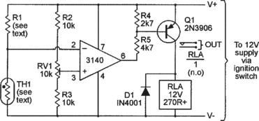
This circuit’s thermistor can be any n.t.c. disc or bead type that has a resistance in the range lk5 to 5k0 at 25°C (the normally-specified ‘nominal resistance value’ temperature). Typically, the TH1 resistance at 0°C is about treble the 25°C value, and in this circuit the R1 value should roughly equal TH1’s ‘0°C’ value; thus, if TH1 has a nominal 25°C value of lk5, R1 needs a value of about 4k5. Note, however, that the precise R1 value is not critical, since balance-control RV1 can compensate for errors in the range −50% to +100% in the R1 value. The actual methods of mounting TH1 and setting RV1 are described later in this section.
In most practical ice-hazard alarm applications the hazard condition may continue intermittently during several hours of driving, and it is thus best to use a flashing-LED type of ‘hazard alarm’ indicator, rather than a continuously-active audible-warning type. Figure 7.16 shows the Figure 7.15 circuit modified to give a flashing-LED alarm output directly, rather than via a relay. In this case Q1 is wired as an emitter-follower, and drives on D1 – a low-cost flashing LED device – when the op-amp output switches low. Note that R4–ZD1 and Q1’s base-emitter volt-drop limit D1’s maximum applied voltage to a safe value of 9.4 volts.

When building either of these ice-hazard alarms, note that thermistor TH1 must be mounted in a small ‘head’ that is fixed to the lower front of the vehicle and connected to the main alarm-unit via twin flex. To make the thermistor head, solder the thermistor to a small tag-board and solder its leads to the twin flex. Coat the whole assembly with waterproof varnish, so that moisture will not affect its apparent resistance, then mount it in a small plastic or metal box and fix it to the lower front of the vehicle. Before fixing the head in place, however, calibrate the alarm system as follows:
Immerse the head in a small container filled with a water and ice mixture. Use a thermometer to measure the temperature of the mixture, and add ice until a steady reading of 0°C is obtained. Now adjust RV1 so that the alarm (RLA or the flashing LED) just turns on; raise the temperature slightly, and check that the alarm turns off again. If satisfactory, the head and the alarm system can now be fixed to the vehicle.
Low-fuel-level/engine-overheat alarms
Two of the most annoying things that can happen to a car driver are to run out of fuel, or to have the engine suddenly fail due to severe overheating, when each of these conditions could easily have been avoided if the driver had noticed the advance-warnings indicated by the vehicle’s fuel gauge or the engine’s water-temperature gauge readings. Both of these events can often be avoided by fitting the vehicle with simple circuits that monitor the standard fuel or temperature gauges and activate a flashing-LED alarm under potential ‘danger’ conditions. Two such circuits are shown in this section; both use the same flashing-LED type of output stage as the Figure 7.16 circuit, but can be made to give relay outputs by replacing these with the type of output stage used in the Figure 7.15 circuit.
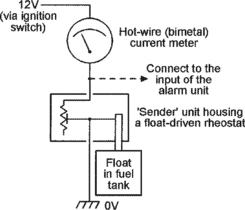
Most reasonably-modern vehicles are fitted with an analogue fuel-level gauge circuit that takes the basic form shown in Figure 7.17. Here, the gauge is actually a hot-wire (bimetal) current meter that is wired in series with a ‘sender’ unit that is mounted in the fuel tank and consists of a float-driven rheostat that presents a high resistance (and a low current-meter reading) when the tank is empty, and a low resistance (and a high current-meter reading) when the tank is full. Note that the output voltage of the sender rises as the fuel level falls, and a low-fuel-level alarm can thus take the basic form of a simple over-voltage alarm. A suitable ‘flashing-LED’ alarm circuit is shown in Figure 7.18.

Before starting to build the Figure 7.18 circuit, check that you can gain easy access to the tank-mounted sender unit or the rear of the fuel gauge, and that the sender’s output voltage varies in the way described above. In the Figure 7.18 circuit, the 3140 op-amp is wired as a voltage comparator, with a pre-set fraction of the supply voltage applied to pin-3 via multi-turn pot RV1, and with half of the sender’s output voltage applied to pin-2 via the R1–R2 potential divider. The op-amp’s output goes low and activates the flashing-LED (via Q1) when the pin-2 voltage rises above the pre-set pin-3 value.
To set up the Figure 7.18 circuit, wait until the fuel falls to the required ‘danger’ level, then connect the unit to the vehicle’s supply via the ignition switch and trim RV1 so that the flashing-LED just turns on. Check that the flashing-LED turns off when the fuel level is increased by a modest amount.
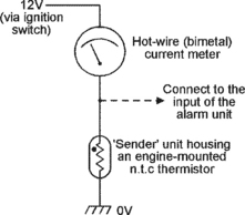
Most reasonably-modern vehicles are fitted with an analogue engine-temperature gauge circuit that takes the basic form shown in Figure 7.19. Here, the gauge is a hot-wire current meter that is wired in series with a ‘sender’ that is simply an engine- or radiator-mounted n.t.c. thermistor and presents a high resistance (and a low current-meter reading) at low temperatures, and a low resistance (and a high current-meter reading) when the engine is at or above its normal running temperature (about 105°C absolute maximum in modern engines). Note that the output voltage of the sender falls as the engine temperature rises, and an engine over-heat alarm can thus take the basic form of a simple under-voltage alarm. A suitable ‘flashing-LED’ alarm circuit is shown in Figure 7.20.

Before starting to build the Figure 7.20 circuit, gain access to the sender unit and check that its output voltage varies in the way described above. In the Figure 7.20 circuit, the 3140 op-amp is wired as a voltage comparator, with a pre-set fraction of the supply voltage applied to pin-2 via multi-turn pot RV1, and with the sender’s output voltage applied to pin-3 via R2–R3. The op-amp’s output goes low and activates the flashing-LED (via Q1) when the pin-3 voltage falls below the pre-set pin-3 value.
To set up the Figure 7.20 circuit, connect it to the vehicle’s supply via the ignition switch, temporarily disable the cooling fan, run the engine up to a fairly high ‘X’ temperature and trim RV1 so that the flashing-LED just turns on, then stop the engine and let it cool down. Now restart the engine and check that the flashing-LED remains off until ‘X’°C is reached. If all is well, turn the LED off via RV1, run the engine up to its red-line ‘overheat’ temperature, then reset RV1 so that the LED turns on. Finally, stop the engine and re-enable the cooling fan.
Lights-are-on alarms
Most modern automobiles are fitted – as standard equipment – with a lights-are-on reminder unit that emits a low-power audible alarm signal that warns the driver, as he/she open the driver’s door, if the car lights have been left on. ‘Lights-are-on’ alarm units of this basic type are easy to build and are fairly easy to add to most older types of vehicle, and come in two basic types. Type-1 is for use in very old vehicles that are not fitted with a courtesy light that is switched automatically via a conventional door-activated microswitch, and Type-2 is for use in vehicles that are fitted with such a courtesy light system.
Figure 7.21 illustrates the basic operating principles of a Type-1 lights-are-on alarm that is added to a vehicle with a 12V negative-ground electrical system. Here, the actual alarm consists of a low-power 15-second buzzer or siren unit that has its supply lines wired in series with diode D1 so that current can only flow through the unit (and thus activate the buzzer/siren) when point-X is many-volts positive to point-Y, and in the diagram this situation only occurs when ‘lights’ switch S1 is in the ON (Side or Head) position and ‘ignition’ switch S2 is turned OFF. Thus, if the lights are left on, the alarm unit sounds-off as soon as the ignition is switched off, but mutes automatically after 15 seconds.

Figure 7.22 illustrates the basic operating principles of a Type-1 lights-are-on alarm that is added to a vehicle with a 12V positive-ground electrical system. Here, the positions of the ‘X’ and ‘Y’ points are simply transposed, so that the alarm again activates only when ‘light’ switch S1 is ON and ‘ignition’ switch S2 is OFF.
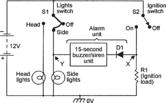
Figure 7.23 shows a simple but practical version of a Type-1 ‘lights-are-on’ alarm unit. Here, Q1–Q2 are wired as a modified complementary astable multivibrator that has its power supplied via D1 and uses a 64R low-power speaker as the collector load of Q2, which is a 2N3704 type and has a peak collector current rating of 800mA. The astable’s action is such that it generates a loud and fairly high alarm tone when power is initially applied, but the volume and frequency then decay steadily down to zero over a period of about 15 seconds. The decay time is controlled by R3–C2, and the initial frequency is controlled by R3–R4 and C1. To use the unit, simply connect its ‘X’ and ‘Y’ points in the appropriate way shown in Figure 7.21 or 7.22.
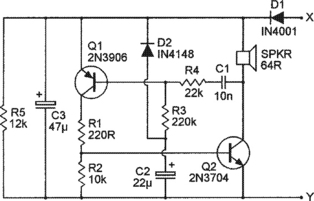
Figure 7.24 and 7.25 illustrate the basic operating principles of Type-2 lights-are-on alarms that are added to vehicles with 12V negative-ground or positive-ground electrical systems. The Type-2 system is similar to the Type-1 system, except that the alarm unit is wired between ‘lights’ switch S1 and dome-light-activating door-switch S2, so that the alarm only sounds if the lights are on when the driver’s door is open.
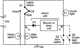

The above system is used on most modern vehicles, in which the dome light uses separate circuits for its ‘courtesy’ and ‘reading’ lights. A snag with most older vehicles is that they use a single light-bulb to perform both of these functions, with the ‘reading’ switch wired in parallel with S2, as shown by S3 in Figures 7.24 and 7.25, and as a consequence the alarm can be activated by either of these switches. The easiest way around this snag is to use an auto-turn-off alarm unit that, like the Type-1 unit, only sounds for a dozen or so seconds when activated. The alarm unit can thus take the simple ‘monotone’ form shown in the Figure 7.23 circuit, or can take the more attractive ‘warble-tone’ form shown in the Figure 7.26 circuit.
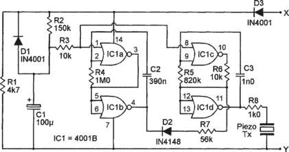
The Figure 7.26 circuit is based on the warble-tone circuits that are shown in Figures 2.17 and 2.23 and are fully described in Chapter 2. In brief, however, IC1a–IC1b and R4–C2 are wired as a gated l.f. (low-frequency) astable and IC1c–IC1d and R5–C3 form a gated h.f. (high-frequency) astable. Both astables are gated via the R2–C1 time-constant network, and are on when C1’s output is below (roughly) half-supply volts and off when C1’s output is above half-supply volts. When the astables are gated on, the l.f. astable frequency-modulates the h.f. astable (via D2–R7–R6), which has its output fed to piezo output transducer Tx via R8.
When power is connected to the Figure 7.26 circuit, C1 is initially fully discharged, so both astables are gated on and generate a warble-tone sound in the piezo Tx, but C1 then charges up via R2 and after a delay of about 15 seconds (determined by R2–C1) gates both astables off, silencing the piezo Tx. When the unit’s power connections are removed, C1 rapidly (in a second or so) discharges via D1–R1, and the unit is then ready to repeat its operating sequence when power is connected again.
A headlight time-delay switch
Headlight time-delay switches are simple add-on units that, when activated by a push switch, turn a car’s headlights on for just a few minutes, during which the owner can leave and lock the vehicle, walk along a drive or pathway that is well lit by the headlights, and then enter the security of a safe building before the lights automatically turn off again. Figure 7.27 shows a practical transistor version of such a circuit.

In Figure 7.27, Q1 is an emitter follower that uses R3–R4 as its emitter load but has ‘bootstrapped’ resistor R2 wired between its base and emitter, so that R2’s impedance – as seen from Q1’s base – is many times greater than its dc resistance value. C1 and Q1’s input impedance (which equals the parallel values of R2’s impedance and Q1’s base impedance) form a C–R time-constant network. The action of Q1 and this network is such that, when power is first connected to the circuit by briefly closing push-button switch S1, C1 is fully discharged and thus pulls Q1’s base and emitter up to almost the full positive supply voltage, thus driving relay-activating common-emitter amplifier Q2 on via R3; as relay RLA turns on, contacts RLA/1 close and lock the supply on, and contacts RLA/2 close and turn the vehicle’s headlights on.
As soon as power is connected to the circuit, C1 starts to charge up via the very high parallel impedances of R2 and Q2’s base, and Q2’s emitter voltage (and the current fed into Q2’s base via R3) starts to decay exponentially until, after a delay of about two minutes, these values fall so low that RLA turns off, thus breaking the supply connection as RLA/1 opens and turning off the headlights as RLA/2 opens. C1 discharges rapidly via R1–D1 when the circuit’s power connection is broken.
A rear-screen heater timer
Automobile rear-screen heaters draw typical operating currents of about 15 amps and thus place a heavy strain on the vehicle’s electrical generating system. If the heater is inadvertently left on for long periods, this strain can greatly reduce the generator’s reliability and working life. Consequently, most modern automobiles are fitted with push-button operated rear-screen heater controllers that turn the heater off automatically after an operating period of about 15 minutes. Reliability-enhancing units of this basic type can easily be added to older vehicles, and – to conclude this chapter – Figure 7.28 shows a practical circuit of this type.
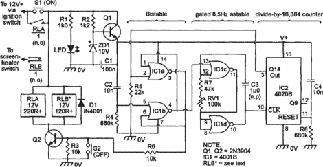
The Figure 7.28 circuit incorporates a simple voltage regulator built around transistor Q1, a stable 16-minute timer built around IC1 and IC2, and relays RLA (which controls the circuit’s semi-latching function) and RLB (which controls the rear-screen heater’s power feed), and derives its power feed via the vehicle’s ignition switch. The complete circuit operates as follows.
The Figure 7.28 circuit is turned on by briefly closing push-button switch S1. As S1 closes, the LED illuminates, a stable 9.4V supply is applied to the IC1–IC2 timer circuit via Q1, and ‘reset’ pulses are fed to the IC1a–IC1b bistable (via C2–R4) and the IC2 counter (via C4–R8). As the bistable resets, its pin-3 output flips high and turns on RLA and RLB via Q2; as the relays turn on, the RLA/1 contacts close, shunting S1 and locking-on the circuit’s supply connection, and RLB/1 contacts close and connect power to the rear-screen heater. Simultaneously, as the IC1a–IC1b bistable resets, its pin-4 output flips low and turns on the IC1c–IC1d gated astable, which starts feeding clock pulses into pin-10 of the IC2 counter at an 8.5Hz rate. Sixteen minutes later, on arrival of the astable’s 8192nd clock pulse, the pin-3 output of IC2 flips high and changes the state of the IC1a–IC1b bistable, which simultaneously gates off the astable and removes Q2’s base drive, thus turning off both relays; as RLA turns off it removes the timer’s supply connection, and as RLB turns off it removes power from the rear-screen heater.
Thus, when the vehicle’s ignition is turned on, the Figure 7.28 circuit connects power to the rear-screen heater as soon as S1 is closed, but removes it again automatically after 16-minutes; if desired, the timing period can be ended prematurely by briefly closing S2, thus turning off both relays. The circuit’s timing period can, if you wish, be set to precisely 16 minutes by connecting a LED and 2k7 series resistor between pins 12 and 8 (0V) of IC2 and trimming RV1 so that the LED operates with precise 30-second on and off periods. When building the circuit, note that RLA’s contacts have to pass maximum currents of less than 200mA, and RLA can thus be almost any general-purpose relay, but that RLB’s contacts have to pass the full operating current of the rear-screen heater (typically 15A), and RLB must thus be a dedicated heavy-duty ‘automobile’ relay.