
Optoelectronic security circuits
Optoelectronic circuits – which respond to either visible or invisible (usually infra-red) light levels – are widely used in modern domestic and commercial security systems. Optoelectronic security circuits come in three basic types, the first of which is the simple ‘visible-light-level’ type that reacts when a light level goes above or below a preset value. The second type is the light-beam alarm, which reacts when a person, object or animal breaks or reflects a projected visible or infra-red (IR) light beam. The third type is the passive infra-red (PIR) detector, which is sensitive to the heat-generated infra-red energy radiated by the human body, and thus reacts when a human or other large warm-blooded animal comes within the sensing range of the PIR detector. Practical optoelectronic circuits of all of these types are described in this chapter.
‘Visible-light-level’ circuits
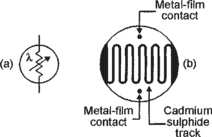
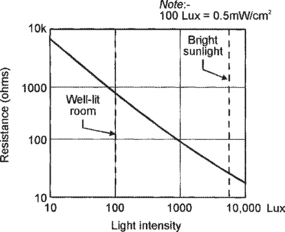
Most optoelectronic circuits that are designed to respond to normal visible light use a cadmium sulphide (CdS) LDR (light-dependent resistor) as their light-sensing element or photocell. Figure 3.1 shows an LDR’s circuit symbol and basic construction, which consists of a pair of metal film contacts separated by a snake-like track of light-sensitive cadmium sulphide film; the structure is housed in a clear plastic or resin case. Figure 3.2 shows the typical photoresistive graph that applies to an LDR with a face diameter of about 10mm; the LDR acts as a high resistance (typically hundreds of kilohms) under dark conditions, falling to about 900R at a light intensity of 100 Lux (typical of a well lit room) or about 30R at 8000 Lux (typical of bright sunlight). Note that although most of the practical circuits shown throughout this ‘Visible-light-level’ section of this chapter are shown using an ORP12 photocell, they will in fact work well with almost any general-purpose LDRs with face diameters in the range 3mm to 12mm.
Simple relay switches and alarms
The simplest ‘visible-light-level’ security circuits are the types that are designed to activate when the light level goes through a large change, such as from near-dark to a moderately high level, or vice versa. Some circuits of this type function as ‘light-activated’ units that switch on a relay or safety mechanism or sound an alarm when light enters a normally dark area such as the inside of a storeroom, wall safe, or security case, etc. Other circuits are designed as ‘dark-activated’ units, and activate when the light level drops well below some nominal value. Figures 3.3 to 3.7 show some simple circuits of these types.


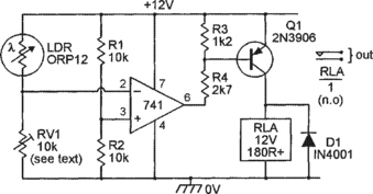
The Figure 3.3 circuit is that of a simple non-latching light-activated relay switch. Here, R1–LDR and R2 form a potential divider that controls the base-bias of Q1. Under dark conditions the LDR resistance is very high, so negligible base-bias is applied to Q1, and Q1 and relay RLA are both off. When light enters the normally dark area and falls on the LDR face, however, the LDR resistance falls to a fairly low value and base-bias is applied to Q1, which thus turns on and activates the relay and its RLA/1 contacts, which can be used to control external circuitry. The relay can be any 12V type with a coil resistance of 180R or greater.
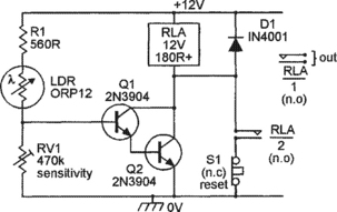
The simple Figure 3.3 circuit has a fairly low sensitivity, and has no facility for sensitivity adjustment. Figure 3.4 shows how these deficiencies can be overcome by using a super-alpha-connected pair of transistors in place of Q1, and by using sensitivity control RV1 in place of R2; this circuit can be activated by LDR resistances as high as 200k (i.e. by exposing the LDR to very small light levels), and draws a standby current of only a few microamps under ‘dark’ conditions. The diagram also shows how the circuit can be made to give a self-latching action via relay contacts RLA/2; normally-closed push-button switch S1 enables the circuit to be reset (unlatched) when required.
Figure 3.5 shows an LDR used in a simple dark-activated circuit that turns relay RLA on when the light level falls below a value that is pre-set via RV1. Here, R1 and LDR act as a potential divider that is fed with a pre-set dc voltage from RV1 and generates an output voltage that rises as the light level falls, and vice versa. This generated voltage is buffered by emitter follower Q1 and used to control the relay via common-emitter amplifier Q2 and current-limiting resistor R3. Thus, when the light level falls below the preset value the R1–LDR divider’s output voltage reaches a large enough level to activate both Q1 and Q2, and the relay turns on.
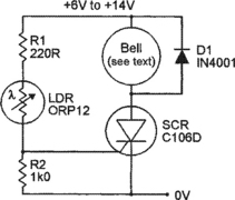
Figures 3.6 and 3.7 show simple SCR (silicon controlled rectifier) circuits that – under the light-sensitive ‘alarm’ condition – activate an ordinary self-interrupting electromechanical alarm bell. This bell must (when the specified C106D SCR is used) consume an operating current of less than 2A, and the circuit’s supply voltage must be at least 1V greater than the bell’s nominal operating voltage.
The Figure 3.6 circuit is a simple non-latching one, in which the alarm bell is wired in series with an SCR that receives its gate drive from the positive supply rail via the R1–LDR–R2 potential divider. Thus, under dark conditions the LDR resistance is very high, so negligible gating voltage appears across R2, and the SCR and alarm are both off. When light enters the normally dark area and falls on the LDR face, however, the LDR resistance falls to a fairly low value, and if this value is below roughly 10k the LDR passes enough current to gate the SCR into the ‘on’ mode, thus sounding the alarm bell. Most LDRs (including the ORP12) give a resistance of less than 10k when exposed to low-intensity room lighting or the light of a torch, so this circuit operates as soon as it is exposed to a moderate amount of illumination.
Note in the above circuit that, although the SCR is a self-latching device, it automatically unlatches each time that the bell enters a self-interrupt phase (and the SCR anode current drops to zero). Consequently, the alarm bell automatically turns off when the light level falls back below the SCR’s ‘trip’ level.
The Figure 3.6 circuit has a fairly low sensitivity and has no facility for sensitivity adjustment. Figure 3.7 shows how these deficiencies can be overcome by using RV1 in place of R2 and by using Q1 as a buffer between the LDR and the SCR gate; this circuit can be activated by LDR resistances as high as 200k (i.e. by exposing the LDR to very small light levels). This diagram also shows how the circuit can be made self-latching by wiring R4 across the bell so that the SCR anode current does not fall to zero as the bell self-interrupts. Switch S1 enables the circuit to be reset (unlatched) when required.
Siren-output alarms
The Figure 3.2 to 3.7 circuits are designed to give either alarm-bell or relay outputs. In some applications an electronic ‘siren sound’ output may be preferable, and Figures 3.8 and 3.9 show low-power (up to 520mW) speaker-output circuits of this type. The Figure 3.8 circuit gives non-latching operation and develops a pulsed-tone output signal. The Figure 3.9 circuit gives self-latching operation, and develops a monotone output signal. Both circuits are designed around a 4001B CMOS IC.


In the Figure 3.8 circuit the IC’s two left-hand gates are wired as a low-frequency (6Hz) gated astable multivibrator that is activated via the light-sensitive LDR–RV1 potential divider, and the two right-hand gates are wired as a gated 800Hz astable that is activated by the 6Hz astable. Under dark conditions the LDR–RV1 output voltage is high and both astables are gated off, and the circuit consumes a fairly low standby current, but under bright conditions the LDR–RV1 output voltage is low and both astables are activated, with the left-hand astable gating the 800Hz astable on and off at a 6Hz rate, thus generating a pulsed 800Hz tone in the speaker.
In the self-latching Figure 3.9 circuit the IC’s two left-hand gates are wired as a simple bistable multivibrator that can be activated (SET) by a high voltage on the output of the light-sensitive LDR–RV1 potential divider, and the two right-hand gates are wired as a gated 800Hz astable that is activated by the bistable’s output. Under normal dark conditions the output of the LDR–RV1 divider is low, the bistable output is in the high ‘RESET’ state, thus gating the astable off, and the circuit consumes only a small standby current. When the LDR is exposed to light, however, the LDR–RV1 junction goes high, flipping the self-latching bistable into the SET mode, in which its output goes low and gates on the 800Hz astable, thus generating a monotone speaker signal. Once it has been activated, the circuit can only be turned off again by removing the LDR’s illumination and briefly closing RESET switch S1, at which point the bistable output resets to the high state and the astable is gated off again.
Note that the trigger points of the Figure 3.8 and 3.9 circuits occur at the point at which the LDR–RV1 junction voltage swings above or below IC1’s ‘transition’ voltage value, which lies somewhere between one-third and two-thirds of the supply voltage value. In practice, the light-trigger points of these circuits are not greatly affected by supply voltage variations. Also note that, when using the output stages shown in the diagrams, these two circuits each give maximum output powers of only 520mW into the 64R speakers, but that these powers can be boosted to as high as 13.2 watts by replacing the Q1 output stages with the power-boosting circuits shown in Figures 2.21 or 2.22 (in Chapter 2).
Precision relay-switching circuits
The relay-switching circuits of Figures 3.3 to 3.5 are fairly sensitive to variations in supply voltage and temperature, and are not suitable for use in a precision light-sensing application. Figure 3.10 shows a very sensitive light-sensitive relay-driving circuit that is not influenced by such variations, and is thus suitable for use in many precision light-sensing applications, and which turns the relay on when the light level rises above a pre-set value. In this case, LDR–RV1 and R1–R2 are connected in the form of a Wheatstone bridge, and the op-amp and Q1–RLA act as a highly sensitive balance-detecting switch. The bridge balance point is quite independent of variations in supply voltage and temperature, and is influenced only by variations in the relative values of the bridge components.
In Figure 3.10, the LDR and RV1 form one arm of the bridge, and R1–R2 form the other arm. These arms can actually be regarded as potential dividers, with the R1–R2 arm applying a fixed half-supply voltage to the non-inverting input of the op-amp, and with the LDR–RV1 divider applying a light-dependent variable voltage to the inverting terminal of the op-amp. In use, RV1 is adjusted so that the LDR–RV1 voltage rises slightly above that of R1–R2 as the light intensity rises to the desired trigger level, and under this condition the op-amp output switches to negative saturation and thus drives RLA on via Q1 and biasing resistors R3-R4. When the light intensity falls below this level, the op-amp output switches to positive saturation, and under this condition Q1 and the relay are off.
The Figure 3.10 circuit is very sensitive and can detect light-level changes too small to be seen by the human eye. The circuit can be modified to act as a precision dark-activated switch (which turns the relay on when the light level falls below a pre-set value) by either transposing the inverting and non-inverting input terminal connections of the op-amp, or by transposing RV1 and the LDR. Figure 3.11 shows a circuit using the latter option. This diagram also shows how a small amount of hysteresis can be added to the circuit via feedback resistor R5, so that the relay turns on when the light level falls to a particular value, but does not turn off again until the light level rises a substantial amount above this value (this action helps prevent spurious switching due to passing shadows, etc., in automatic lighting-control circuits). The hysteresis magnitude is inversely proportional to the R5 value, being zero when R5 is open circuit.

Figure 3.12 shows how a precision combined light-/dark-activated switch (which activates a single relay if the light intensity rises above one pre-set value or falls below another pre-set value) can be made by combining the ‘light’ and ‘dark’ switch circuits of Figures 3.10 and 3.11 To set up this circuit, first pre-set RV1 so that roughly half-supply volts appear on the LDR-RV1 junction when the LDR is illuminated at the mean or normal intensity level. RV2 can then be pre-set so that RLA turns on when the light intensity falls to the desired dark level, and RV3 can be pre-set so that RLA activates when the light rises to the desired ‘bright’ level.
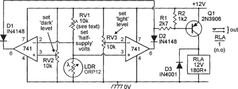
Note in the Figure 3.10 to 3.12 ‘precision’ circuits that the basic RV1 value should be roughly double that of the LDR resistance value at the desired ‘trigger’ light levels, so that RV1’s slider is reasonably close to its central position under this condition. Thus, the RV1 value may have to be reduced below 10k if a circuit is set to trigger under very bright conditions, or may have to be increased above 10k if used to trigger under very dark conditions.
Precision alarm-sounding circuits
The basic op-amp based precision circuits of Figures 3.10 to 3.12 can easily be used in conjunction with some of the alarm-bell activator or siren-sound generator circuits already shown in this chapter, to make various precision alarm-sounding circuits. Figure 3.13, for example, shows modified versions of the basic Figure 3.6 and 3.10 circuits combined to make a precision light-activated alarm bell circuit that can easily be changed into a dark-activated unit by simply transposing RV1 and the LDR. Note that the op-amp’s supply line is decoupled from that of the bell via D3 and C1.
Similarly, Figure 3.14 shows modified versions of the basic Figure 3.8 and 3.10 circuits combined to make a precision light-activated pulsed-tone alarm with built-in hysteresis. The hysteresis is controlled by R3, which can have its value altered to obtain different hysteresis values, or can be removed if hysteresis is not needed.

Light-beam alarm circuits
A light-beam alarm system consists of a focused light-beam transmitter (Tx) and a focused light-beam receiver (Rx), and may be configured to give either a direct-light-beam or a reflected-light-beam type of optical contact operation. Figure 3.15 shows the basic elements of a direct-light-beam type of alarm system, in which the sharply focused Tx light-beam is aimed directly at the light-sensitive input point of the Rx unit, which (usually) is designed to activate an external alarm or safety mechanism if a person, object, or piece of machinery enters the light-beam and breaks the optical contact between the Tx and Rx.

Figure 3.16 shows a very simple example of a lamp-and-LDR direct-light-beam system that activates an alarm-bell if the beam is interrupted. The beam is generated via an ordinary electric lamp and a lens, and is focused (via a ‘collector’ lens) on to the face of an LDR in the remote Rx unit, which operates as a dark-activated alarm. Normally, the LDR face is illuminated by the light-beam, so the LDR has a low resistance and very little voltage thus appears on the RV1–LDR junction, so the SCR and bell are off. When the light-beam is broken, however, the LDR resistance goes high and enough voltage appears on the RV1–LDR junction to trigger the SCR, which drives the alarm bell on; R3 is used to self-latch the alarm.
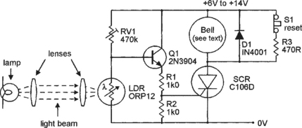
Figure 3.17 shows the basic elements of a reflected-light-beam type of alarm system, in which the Tx light-beam and Rx lens are optically screened from each other but are both aimed outwards towards a specific point, so that an optical link can be set up by a reflective object (such as metallic paint or smoke or fog particles) placed at that point. This type of system is usually designed to activate an alarm when the presence of such an object is detected, but can also be configured to give the reverse action, so that the alarm activates if a reflective object is legally or illegally removed.

Units of the Figure 3.17 type were once widely used in conjunction with reflection-type fog and smoke detector units; Figure 3.18 shows a sectional view of a smoke detector unit of this type. Here, the lamp and LDR are mounted in an open-ended but light-excluding box, in which an internal screen prevents the lamp-light from falling directly on the LDR face. The lamp is a source of both light and heat, and the heat causes convection currents of air to be drawn in from the bottom of the box and to be expelled through the top. The inside of the box is painted matt black, and the construction lets air pass through the box but excludes external light.
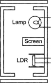
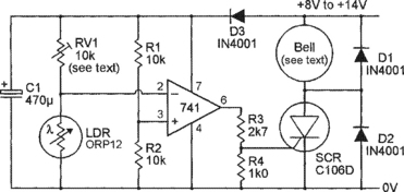
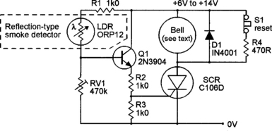
Thus, if the convected air currents are smoke-free, no light falls on the LDR face, and the LDR presents a high resistance. If the air currents do contain smoke, however, the smoke particles cause the light of the lamp to reflect on to the LDR face and so cause a large and easily detectable decrease in the LDR resistance. Figure 3.19 shows the practical circuit of a reflection-type smoke alarm that can be used with this detector; the circuit acts in the same way as the improved Figure 3.7 light-activated alarm circuit.
IR light-beam alarm basics.
Simple lamp-and-LDR light-beam alarms of the types described in the last section have several obvious disadvantages in most modern security-alarm applications. Their light-beams are, for example, clearly visible to an intruder, the transmitter’s filament lamp is unreliable, and the systems are (because the transmitter’s filament lamp wastes a lot of power) very inefficient. In practice, virtually all modern light-beam security systems operate in the invisible infra-red (rather than visible light) range, and use one or more pulse-driven IR LEDs to generate the transmitter’s ‘light-beam’, and use matching IR photodiodes or phototransistors to detect the beam at the receiver end of the system. The graph of Figure 3.20 conveys some useful information regarding the spectral response of the human eye and of general-purpose and IR photodiodes and phototransistors.

Figure 3.20 Typical spectral response curves of (a) the human eye and (b) general-purpose and (c) IR photodiodes/phototransistors
Thus, the human eye is sensitive to a range of electromagnetic light radiation; it has a peak spectral response to the colour green, which has a wavelength of about 550nm, and has relatively low sensitivity to the colour violet (400nm) at one end of the visible-light spectrum and to dark red (700nm) at the other; the human eye is blind to electromagnetic light radiation beyond this narrow spectrum. Optoelectronic semiconductor devices such as photodiodes and phototransistors have spectral responses that are determined by the chemistry of their semiconductor junction material; general-purpose ‘light-sensitive’ types have (as shown in Figure 3.20) typical spectral responses that straddle the human visibility spectrum, but IR types operate at a peak wavelength of about 900nm and generate an output spectrum that is well beyond the range of normal human visibility. IR light-beams are thus invisible to human eyes.
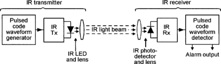
A simple IR direct-light-beam intrusion detector or alarm system can be made by connecting an IR light-beam transmitter and IR receiver in the basic way shown in Figure 3.21. Here, the transmitter feeds a coded pulse-type signal (often a simple squarewave) into an IR LED that has its output focused into a fairly narrow beam (via a moulded-in lens in the LED casing) that is aimed at a matching IR photodetector (phototransistor or photodiode) in the remotely placed receiver. The system action is such that the receiver output is ‘off’ while the light-beam reaches the receiver, but turns on and activates an external alarm or other mechanism if the beam is interrupted by a person or other object. This basic type of system can be designed to give a useful detection range of up to 20 metres when used with additional optical focusing lenses, or up to 5 metres without extra lenses.
Note that the simple Figure 3.21 light-beam alarm system works on a strict line-of-sight principle between the Tx and Rx lenses, and the alarm may thus activate if any object with a diameter greater than the smaller of the two lenses enters the beam’s line-of-sight. Thus, a weakness of this simple system is that it can easily be false-triggered by relatively small insects entering the beam or resting on one of the lenses. The improved dual-light-beam system shown in Figure 3.22 does not suffer from this particular defect.
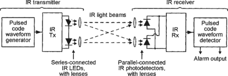
The Figure 3.22 system is basically similar to that already described, but transmits the IR beam via two series-connected LEDs that are spaced about 75mm apart, and receives the beam via two parallel-connected photodetectors that are also spaced about 75mm apart. Thus, each photodetector can detect the beam from either LED, and the receiver’s alarm will thus activate only if both beams are broken simultaneously, and this will normally only occur if a large (greater than 75mm) object is placed within the composite beam. This system is thus virtually immune to false triggering by insects, etc.
Note that, as well as giving excellent false-alarm immunity, the dual-light-beam system also gives (at any given LED drive-current value) double the effective detection range of the simple single-beam system, since it has twice as much effective IR transmitter output power and twice the receiver sensitivity.
IR system waveforms
IR light-beam systems are usually used in conditions in which high levels of ambient or background IR radiation (generated by natural or artificial heat sources) already exist. To enable the systems to differentiate against this background radiation and give good effective detection ranges, the transmitter beams are invariably pulse-coded, and the receivers are fitted with matching pulse-code detection circuitry. In practice, the transmitter beams usually use either a continuous-tone or a tone-burst type of pulse-coding, as shown in Figure 3.23.
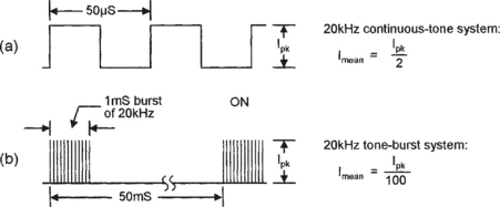
IR LEDs and photodetectors are very fast-acting devices, and the effective range of an IR beam system is thus determined by the peak currents fed into the transmitting LED (or LEDs), rather than by the mean LED current. Thus, if the waveforms of Figure 3.23 are used in IR transmitters giving peak LED currents of 100mA, both systems will give the same effective operating range, but the Figure 3.23(a) continuous-tone transmitter will consume a mean LED current of 50mA, while the tone-burst system of Figure 3.23(b) will consume a mean current of only 1mA (but will require a more complex circuit design).
The operating parameters of the tone-burst system require careful consideration, since this type of IR intrusion detecting system actually works on a ‘sampling’ principle and is usually intended to detect the presence of a human intruder. Note that humans moving at normal walking speed take about 200mS to pass any given point, so IR light-beam systems do not need to be switched on continuously to detect a human intruder, but only need to be turned on for brief ‘sampling’ periods at repetition periods that are far shorter than 200mS (at, say, 50mS); the actual sample period can be very short relative to the repetition period, but must be long relative to the tone frequency period. Thus, a good compromise is to use a 20kHz tone with a burst or ‘sample’ period of 1mS and a repetition period of 50mS, as shown in the waveform example of Figure 3.23(b).
IR system design
The first step in designing any electronic system is that of devising the system’s block diagrams. Figure 3.24 shows a suitable block diagram of a continuous-tone IR light-beam intrusion alarm/detector system, and Figure 3.25 shows the block diagram of a tone-burst version of the system. Note that a number of blocks (such as the IR output stage, the tone pre-amp, and the output driver) are common to both systems.
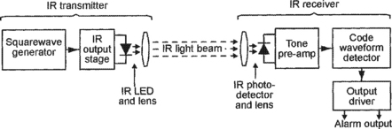

The continuous-tone system (Figure 3.24) is very simple, with the transmitter comprising nothing more than a squarewave generator driving an IR output stage, and the receiver comprising a matching tone pre-amplifier and code waveform detector, followed by an output driver stage that can activate a device such as a relay or alarm, etc.
The tone-burst system (Figure 3.25) is rather more complex, with the transmitter comprising a free-running pulse generator (generating 1mS pulses at 50mS intervals) that drives a 20kHz squarewave generator, which in turn drives the IR output stage that generates the final tone-burst IR light beam. In the receiver, the beam signals are picked up and passed through a matching pre-amplifier and then passed on to a code waveform detector/expander block, which ensures that the alarm does not activate during the ‘blank’ parts of the IR waveform. The output of the expander stage is fed to the output driver.
IR light-beam transmitter circuits
Figure 3.26 shows the practical circuit of a simple continuous-tone dual-light-beam IR transmitter. Here, a standard 555 ‘timer’ IC is wired as an astable multivibrator that generates a non-symmetrical 20kHz squarewave output that drives the two series-connected IR LEDs at peak output currents of about 400mA via R5 and Q1 and the low source impedance of storage capacitor C1. The circuit’s timing action is such that the ON period of the LEDs is controlled by C2 and R2, and the OFF period by C2 and (R1+R2), i.e. so that the LEDs are ON for only about one eighth of each cycle; the circuit thus consumes a mean current of only about 50mA.

The Figure 3.26 circuit can use either TIL38 or LD271 (or similar) ‘high power’ (100mW or greater) IR LEDs. These popular and widely-available LEDs can handle mean currents up to only 100mA or so, but can handle brief repetitive peak currents of up to at least 2.5A. Figure 3.27 shows the outline and connections of these devices, which have a moulded-in lens that focuses the output into a radiating beam of about 60° width; at the edges of the beam the IR signal strength is half of that at the centre of the beam.

Minor weaknesses of the IR output stage (Q1 and R3 to R5) of the Figure 3.26 circuit are that it has a very low input impedance (about 300R), that it gives an inverting action (the LEDs are ON when the input is low), and that the LED output current varies with the circuit’s supply voltage. Figure 3.28 shows an alternative universal IR transmitter output stage that suffers from none of these defects.

In Figure 3.28, the base drive current of output transistor Q2 is derived from Q1 collector, and the Q1 circuit has an input impedance of about 5k0 (determined mainly by the R1 value). Thus, when the circuit’s input is low Q1 is off, so Q2 and the two IR LEDs are also off, but when the input is high Q1 is driven to saturation via R3, thus driving LED1 (a standard red LED) and Q2 and the two IR LEDs on. Note that under this latter condition about 1.8V is developed across LED1, and that about 0.6V less than this (= 1.2V) is thus developed across R4, causing Q2 to act as a constant-current generator that feeds a peak collector current of 1.2V/R4 amps into the two IR LEDs. Thus, this circuit’s peak output current can be set by giving R4 an ohms value of 1.2V/I, where I is the desired peak output current in amps.
Figure 3.29 shows a 20kHz squarewave generator (made from a 555 timer IC) that can be used in conjunction with the Figure 3.28 output circuit to make a continuous-tone IR beam transmitter. In this case the Figure 3.28 circuit’s R4 value should be at least 6R8, to limit the peak IR LED currents to less that 200mA.

Alternatively, Figure 3.30 shows the circuit of a tone-burst generator that gives 1mS bursts of 20kHz at 50mS intervals and which can be used in conjunction with the Figure 3.28 output stage to make an IR tone-bursts transmitter. Here, the IC1a and IC1b sections of a 4011B CMOS quad 2-input NAND gate IC are wired as a free-running asymmetrical astable multivibrator that produces 1mS and 49mS periods; this waveform is inverted and buffered by IC1c and used to gate a 20kHz 555-type squarewave generator via D2, and this squarewave is then buffered and inverted by the final 4011B stage (IC1c), ready for feeding to the input of the Figure 3.28 output stage.

Note when using the Figure 3.30 circuit that R4 in the Figure 3.28 output stage can be given a value as low as 2R2, to give peak output currents of up to 550mA, but that under this condition the transmitter will consume a mean current of little more than 6mA.
IR receiver pre-amp design
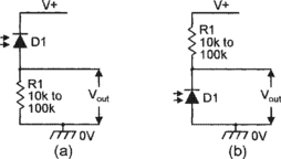
The basic IR input signal to an IR light-beam receiver can be picked up and converted into a proportional current by either an IR photodiode or an IR phototransistor. If a photodiode is used, it can be connected in series with a load resistor (with a typical value in the range 10k to 100k) and used in either of the reverse-biased configurations shown in Figure 3.31 The diode’s basic action is such that its reverse-biased leakage current is proportional to the IR light intensity on its junction, being very low under dark conditions and relatively high when brightly illuminated; this current is converted into a proportional output voltage by R1.
An IR phototransistor can be used by connecting it in either of the basic ways shown in Figure 3.32(a) or (b), in which load resistor R1 has a typical value in the range 1k0 to 33k. Most phototransistors have only two externally-accessible leads (collector and emitter), but a few are 3-lead types with an accessible base lead; a 3-lead device can be used as a phototransistor by connecting it in either of the two basic ways already shown, or can be used as a photodiode by connecting it in the way shown in Figure 3.32(c).
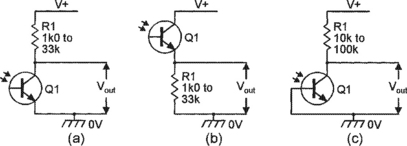
Figure 3.32 (a) and (b); alternative phototransistor configurations, (c); a 3-lead phototransistor used as a photodiode
Note that a phototransistor’s sensitivity is typically one hundred times greater than that of a photodiode, but its maximum operating frequency (typically a few hundred kHz) is proportionally lower than that of a photodiode (typically tens of MHz). Also note in Figures 3.31 and 3.32 that the photosensor exhibits a high sensitivity but a low cut-off frequency if R1 has a high value, and a low sensitivity but high cut-off frequency if R1 has a low value.
Figure 3.33 shows the practical circuit of an IR light-beam receiver that is designed for use with 20kHz continuous-tone or tone-burst single-beam or dual-beam systems, and using IR photodiodes as signal converters. Here, the two IR diodes are connected in parallel and wired in series with R1, so that the converted IR signal is developed across R1 (note that one of these diodes can be removed if the unit is used with a single-beam IR system). The converted R1 signal is amplified by cascaded op-amps IC1 and IC2, which can provide a maximum signal gain of about ×17 680 (= ×83 via IC1 and ×213 via IC2), but have the gain made variable via RV1. These two amplifier stages have their frequency responses centred on 20kHz, with third-order low-frequency roll-off provided via C4–C5–C6 and with third-order high-frequency roll-off provided by C3 and the internal capacitors of the two op-amps.
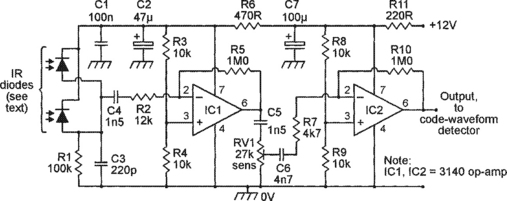
The Figure 3.33 receiver pre-amp circuit can be used with a variety of IR detector diode types, which ideally should be housed in black (rather than clear) infra-red transmissive mouldings, which greatly reduce unwanted pick-up from visible light sources. Figure 3.34 shows the case outline and IR-sensitive face positions of three popular IR photodiodes of this type.

The output of the Figure 3.33 pre-amplifier can be taken from IC2 and fed directly to a suitable code waveform detector circuit, such as that shown in Figure 3.35. Note, however, that if the IR Tx–Rx light-beam system is to be used over ranges less than 2 metres or so, the pre-amp output can be taken directly from IC1 and all the RV1 and IC2 circuitry can be omitted from the pre-amp design.
A code waveform detector
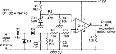
In the Figure 3.35 code waveform detector circuit the 20kHz tone waveforms (from the pre-amp output) are converted into dc via the D1–D2–C2–R5–C3 network and fed (via R6) to the non-inverting input of the 3140 op-amp voltage comparator, which has its inverting input connected to a thermally stable 1V0 dc reference point. The overall circuit action is such that the op-amp output is high (at almost full positive supply rail voltage) when a 20kHz tone input signal is present, and is low (at near-zero volts) when a tone input signal is absent; if the input signal is derived from a tone-burst system, the output follows the pulse-modulation envelope of the original transmitter signal. The detector output can be made to activate a relay in the absence of a beam signal by using the expander/output driver circuit of Figure 3.36.

An expander/output driver
The operating theory of the Figure 3.36 circuit is fairly simple. When the input signal from the detector circuit switches high C1 charges rapidly via D1, but when the input switches low C1 discharges slowly via R1 and RV1; C1 thus provides a dc output voltage that is a ‘time-expanded’ version (with expansion presettable via RV1) of the dc input voltage. This dc output voltage is buffered and inverted via IC1a and used to activate relay RLA via Q1 and an AND gate made from IC1b and IC1c.
Normally, the other (pin-2) input of this AND gate is biased high via R2, and the circuit action is such that (when used in a complete IR light-beam system) the relay is off when the beam is present, but is driven on when the beam is absent for more than 100mS or so. This action does not occur, however, when pin-2 of the AND gate is pulled low; under this condition the relay is effectively disabled.
The R2–C2 network’s purpose is to disable the relay network via the AND gate (in the way just described) for several seconds after power is initially connected to the circuit or after DISABLE switch S1 is briefly operated, thus enabling the owner or other authorized persons to pass through the beam without activating the relay. Note that the relay can be made self-latching, if required, by wiring normally-open relay contacts RLA/2 between Q1 emitter and collector, as shown dotted in Figure 3.36.
IR light-beam system ranges
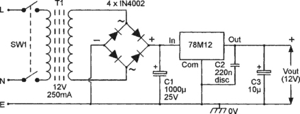
The circuits of Figures 3.33, 3.35, and 3.36 can be directly interconnected to make a complete IR light-beam receiver that can respond to either tone-burst or continuous-tone signals; the receiver must be powered from a well-regulated 12V DC supply unit, such as that shown in Figure 3.37. The practical maximum operating range of a complete IR light-beam security system of this type is greatly affected by the types of lenses used in the system. If additional lenses are not used, but the Tx and Rx are carefully aimed at each other, and the Rx diodes are screened from the effects of visible light by mounting them deep inside aimed tubing, the maximum range should be at least 5 metres, and may be as high as 7 metres. This range can be vastly increased with the help of additional focusing lenses and/or reflectors.
At the Tx end of the system, most of the optical output power of each IR LED is typically radiated over an arc of about 60°, and thus has a fairly low radiation density value; the Tx signal’s radiation density value can easily by increased by a factor of four (thus doubling the system’s effective range) by mounting each IR LED at the focal point of a simple torch-type optical reflector that is aimed at the receiver unit.
At the Rx end of the light-beam system, each IR photodiode has an integral lens that focuses the received IR light on to the diode’s photosensitive area. On 5mm detectors such as the SFH2030F, this lens has a collection area of about 19.6mm2; in this example, the detector’s effective sensitivity can be increased by a factor of four (thus doubling the system’s range) with the help of an external 10mm2 focusing lens, or by a factor 36 (thus increasing the range by a factor of six) with the help of a 30mm2 focusing lens. Thus, if reasonable care is taken in the opto-mechanical design of the IR system, its range can easily be increased to 20 metres, and possibly to 60 metres or more.
PIR movement-detecting systems
IR light-beam alarms are ‘active’ IR units that react to an artificially generated source of IR radiation. Passive IR (PIR) alarms, on the other hand, react to naturally generated IR radiation such as the heat-generated IR energy radiated by the human body, and are widely used in modern security systems. Most PIR security systems are designed to activate an alarm or floodlight, or open a door or activate some other mechanism, when a human or other large warm-blooded animal moves about within the sensing range of a PIR detector unit, and use a pyroelectric IR detector of the type shown in Figure 3.38 as their basic IR-sensing element.
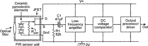
The basic Figure 3.38 pyroelectric IR detector relies on the fact that some special ceramics generate electrical charges when subjected to thermal variations or uneven heating. Modern pyroelectric IR detectors such as the popular PIS201S and E600STO types incorporate two small opposite-polarity series-connected ceramic elements of this type, with their combined output buffered via a JFET source-follower, and have the IR input signals focused onto the ceramic elements by a simple filtering lens, as shown in the basic PIR detector usage circuit of Figure 3.38. It is important to note at this point that the detector’s final output voltage is proportional to the difference between the output voltages of the two ceramic elements.
The basic action of the Figure 3.38 PIR detector is such that, when a human body is within the visual field of the pyroelectric elements, part of that body’s radiated IR energy falls on the surfaces of the elements and is converted into small but detectable variation in surface temperature and corresponding variation in the output voltage of each element. If the human body (or other source of IR radiation) is stationary in front of the detector’s lens under this condition, the two elements generate identical output voltages and the unit’s final ‘difference’ output is thus zero, but if the body is moving while in front of the lens the two elements generate different output voltages and the unit produces a varying output voltage.
Thus, when the PIR unit is wired as shown in the Figure 3.38 basic usage circuit, this movement-inspired voltage variation is made externally available via the buffering JFET and dc-blocking capacitor C1 and can, when suitably amplified and filtered, be used to activate an alarm or other mechanism when a human body movement is detected. In practice, pyroelectric IR detectors of the simple type just described have, because of the small size (usually about 20mm2) and simple design of the detector’s IR-gathering lens, maximum useful detection ranges of roughly one metre. In modern commercial PIR movement detecting security units, however, this range is greatly extended (usually to well over ten metres) with the aid of a large (about 2000mm2) multi-faceted external IR-gathering/focusing plastic lens, which splits the visual field into a number of parallel strips and focuses them onto the two sensing areas of the PIR unit.
Figure 3.39 shows the typical PIR sensing pattern of a commercial ‘intrusion detector’ unit designed to protect a normal-sized room in domestic-type applications. In this example the unit is mounted on a wall at a height of seven feet and is aimed downwards at a shallow angle, and the multi-faceted plastic lens splits the visual field into a large number of vertical and horizontal segments. Any person moving through a single segment will activate a single trigger signal within the PIR sensor; a person moving through the entire visual field will thus produce numerous triggering signals, but a stationary IR source will produce no signals. Most intrusion detectors of this type incorporate ‘event counting’ circuitry that will only generate an alarm-activating output if three or more trigger signals are detected within a few seconds, thus minimizing the chances of a false alarm due to sudden changes in temperature caused by the auto-activation of time-switched security lights, etc.

Figure 3.39 Typical PIR sensing pattern of a commercial ‘intrusion detector’ unit designed for normal domestic-type applications
The lens-generated PIR sensor pattern shown in Figure 3.39 is the type that is often used in burglar-alarm systems to protect a single room in a medium-sized house. Alternative (and usually interchangeable) plastic lens types, offering different ranges and coverage patterns for various special types of application, are available at low cost from many commercial PIR-unit suppliers. Among the most important of these are the ‘pet’ type, in which the field’s vertical span is restricted to 2.5 to 6.6 feet above ground level to avoid activation by domestic pets while giving good sensitivity to normal humans, and the ‘corridor’ type, in which the field’s horizontal span is restricted to about 20 degrees to give long-distance coverage (typically about 30 metres) of narrow corridors and passageways.
Note that, because high-quality commercial PIR security units of this basic type are widely available at comparatively low cost, it is not practicable (on aesthetic and cost-effective grounds) to try to build similar units on a DIY basis.