
Temperature-sensitive security circuits
Temperature-sensitive security circuits can be used to automatically activate alarms or safety devices when one or more monitored temperatures goes above or below a pre-set level, or when two temperatures differ by more than a prescribed amount. Such circuits can be used to give warning of fire, frost, excessive boiler temperature, the failure of a heating system, or overheating of a piece of machinery or a liquid, etc. They may use thermostats, thermistors or various types of solid-state device as their temperature-sensing elements, and may give an audible output via some type of electro-acoustic device (a siren or bell, etc.) or a switched output via some type of relay. A wide range of useful temperature-sensitive security circuits are presented in this chapter.
Thermostat fire-alarm circuits
One of the simplest types of temperature-sensitive circuit is the thermostat-activated fire alarm. Figure 5.1 shows the practical circuit of a relay-aided non-latching alarm of this type. Here, any desired number of n.o. thermostats are wired in parallel and then connected in series with the coil of a relay, and one set of the relay’s n.o. contacts are wired in series with the alarm bell so that the bell operates if the relay turns on. Normally, the thermostats are all open, so the relay and alarm bell are off. Under this condition the circuit consumes zero standby current. At ‘over-heat’ temperatures, on the other hand, one or more of the thermostats closes, and thus turns on the relay and thence the alarm bell. Note that push-button switch S1 is wired in parallel with the thermostats, enabling the circuit to be functionally tested by operating the push-button.
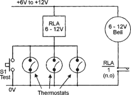
The thermostats used in this and all similar circuits described in this chapter must be n.o. types that close when the temperature exceeds a preset limit. When the thermostats are located in normal living areas they should be set to close at a temperature of roughly 60°C (140°F), but when they are located in unusually warm places – such as furnace rooms or attics – they should be set to close at about 90°C (194°F).
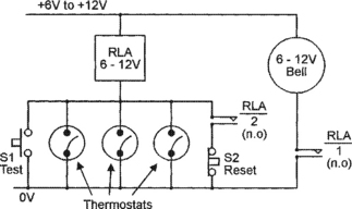
The basic Figure 5.1 circuit gives a non-latching form of operation. If required, the circuit can be made self-latching by wiring a spare set of n.o. relay contacts in parallel with the thermostats, as shown in Figure 5.2. Note that n.c. push-button switch S2 is wired in series with these relay contacts, so that the circuit can be reset or unlatched by momentarily operating S2.
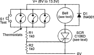
Bell-output fire-alarms can sometimes be activated via an SCR rather than a relay; Figure 5.3 shows a typical circuit of this type. Here, a normal self-interrupting type of alarm bell is wired in series with the SCR anode, and gate current is provided from the positive supply line via the thermostats and via current-limiting resistor R1. Normally the thermostats are open, so the SCR and bell are off, and the circuit passes only a small leakage current. At high temperatures, however, the thermostats close and apply gate current to the SCR via R1, and the alarm bell turns on.
The basic Figure 5.3 circuit gives a non-latching form of operation. The circuit can be made self-latching by wiring shunt resistor R3 across the bell as shown in Figure 5.4, so that the SCR’s anode current does not fall below its latching value when the bell goes into the self-interrupting mode. Note that push-button switch S2 is wired in series with R3 so that the circuit can be reset or unlatched.
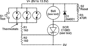
It should be noted that the SCR used in the Figure 5.3 and 5.4 circuits has a current rating of only 2A, so the alarm bell should be selected with this point in mind. Alternatively, SCRs with higher current rating can be used in place of the device shown, but this modification may also necessitate changes in the R1 and R3 values of the circuits. Roughly 1V is dropped across the SCR when it is on, so the circuit’s supply line voltage needs to be about 1V greater than the bell’s nominal operating voltage.
Thermostat fire alarms can be made to generate a siren-type alarm signal directly into a loudspeaker by using the connections shown in Figures 5.5 or 5.6. The Figure 5.5 circuit generates a pulsed-tone non-latching alarm signal, while the Figure 5.6 circuit generates an 800Hz (monotone) self-latching alarm signal. Both circuits are designed around 4001B CMOS digital IC.
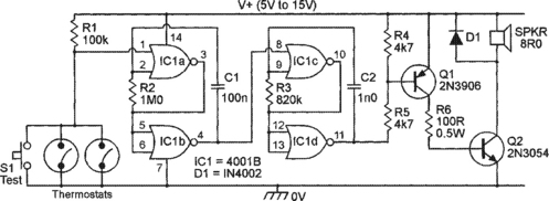
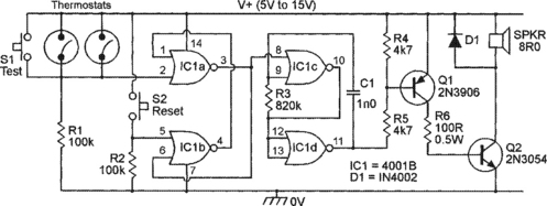
The Figure 5.5 circuit, which gives an output tone of 800Hz pulsed on and off at a rate of 6Hz, is based on the circuit of Figure 2.16 combined with a medium-power (see Figure 2.21) output stage, and the self-latching Figure 5.6 circuit is based on the Figure 2.25 monotone circuit combined with the same medium-power output stage; full descriptions of the operation of these circuits is given in Chapter 2. The Figure 5.5 and 5.6 circuits should be used with 8R0 horn-type speakers (which are far more efficient than normal speakers), and can use any supply in the range 5V to 15V; they give a mean output power (into the speaker) of about 4.5 watts at 12V or 7.0 watts at 15V.
Over-temperature security circuits
Over-temperature security circuits can easily be designed to generate a variety of types of output signal when a monitored temperature rises above a pre-set level, which may range from well below the freezing point of water to well above the boiling point of water. The circuits may be designed to generate an audible signal or to activate some type of relay switch under the ‘alarm’ condition, and may use one or more thermistors or solid-state devices as their temperature-sensing elements.
Several useful over-temperature security circuits are described in this section. Most of them use inexpensive n.t.c. (negative temperature coefficient) thermistors as their temperature-sensing elements. These devices act as temperature-sensitive resistors that present a high resistance at low temperatures and a low resistance at high temperatures. The thermistor circuits described in this and following sections of this chapter have all been designed to work with thermistors that present a resistance of roughly 5k0 at the desired operating temperature; all of these circuits are highly versatile, however, and will in fact work well with any n.t.c. thermistors that present a resistance in the range 1k0 to 20k at the required ‘trip’ temperature.
Figure 5.7 shows the practical circuit of a simple but very sensitive over-temperature switch that has a relay output. Here, the thermistor (TH1) and RV1–R1–R2 are wired in the form of a simple Wheatstone bridge in which R1–R2 generate a fixed half-supply ‘reference’ voltage and TH1–RV1 generate a ‘variable’ output voltage that is inversely proportional to the TH1 temperature and is trimmed (via RV1) so that it almost equals the R1–R2 reference value at the required ‘trip’ temperature. These two voltages are fed to the input of the type 741 op-amp which is used – in conjunction with transistor Q1 – as the bridge’s balance detector and relay driver. The 741 op-amp is used in the open-loop mode in this circuit, and its action is such that its pin-6 output is driven low (to negative saturation) if its pin-3 (non-inverting) input is more than a few millivolts negative to the pin-2 (inverting) input, and is driven high (to positive saturation) if pin-3 is significantly positive to pin-2.
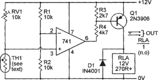
Suppose, then, that the bridge is adjusted so that it is close to balance at the desired ‘trip’ temperature. When the temperature falls below this value the TH1 resistance increases, so the 741’s pin-3 voltage rises above that of pin-2, and the pin-6 output voltage thus goes to positive saturation and consequently applies no base drive to Q1; Q1 and the relay are off under this condition. When the temperature rises above the ‘trip’ value, however, the TH1 resistance decreases and the 741’s pin-3 voltage falls below that of pin-2, and the pin-6 output voltage thus goes to negative saturation and applies heavy base drive to Q1; Q1 and the relay are driven on under this condition. Thus, the relay goes on when the temperature rises above the preset level, and turns off when the temperature falls below the pre-set level.
Important points to note about the Figure 5.7 circuit are that, because it uses the bridge sensing configuration, its accuracy is independent of variations in supply voltage, and that the circuit can respond to TH1 resistance changes of less than 0.1 percent, i.e. to temperature changes of a fraction of a degree. Also note that the basic circuit is quite versatile and can, for example, be converted to a precision under-temperature switch by simply transposing the R1 and TH1 positions, or by transposing the op-amp’s pin-2 and pin-3 connections, or by redesigning the Q1 output stage so that it uses an npn transistor in place of the pnp device. Similarly, there are a number of alternative ways of connecting the circuit so that it operates as a precision over-temperature alarm.
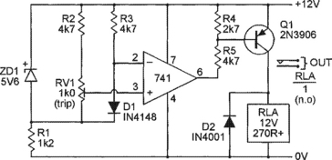
One such alternative, shown in Figure 5.8, acts as a precision over-temperature alarm with an alarm-bell output. The circuit is similar to that shown in Figure 5.7, except that the op-amp’s pin-2 and pin-3 connections are transposed, and the op-amp’s output is used to drive the gate of an SCR rather than the base of a pnp transistor. The circuit action is such that the op-amp output goes to negative saturation at ‘low’ temperatures, thus applying zero gate drive to the SCR, but goes to positive saturation at ‘high’ temperatures, thus driving the SCR and the alarm bell on. The SCR specified in this circuit has a mean current rating of only 2A, so the alarm bell (a self-interrupting type) must be selected with this point in mind.

The Figure 5.7 and 5.8 circuits use thermistors with nominal trip-level resistance values of 5k0 as their temperature-sensing elements, and these thermistors dissipate several milliwatts of power under actual working conditions. In some special applications this power dissipation may cause enough self-heating of the thermistor to upset its thermal sensing capability. In such cases an alternative type of temperature-sensing device may have to be used.
Ordinary silicon diodes have temperature-dependent forward volt-drop characteristics, and can thus be used as temperature-sensing elements. Typically, a silicon diode gives a forward volt drop of about 600mV at a current of 1mA. If this current is held constant, the volt drop changes by about −2mV for each degree Centigrade increase in diode temperature. All silicon diodes have similar thermal characteristics. Since the power dissipation of the diode is a mere 0.6mW under the above condition, negligible self-heating takes place in the device, which can thus be used as an accurate temperature sensor.
Figure 5.9 shows how general-purpose silicon diode D1 can be used as a thermal sensing element in an op-amp over-temperature relay-switch circuit. Here, zener diode ZD1 is wired in series with R1 so that a constant 5.6V is developed across the two potential dividers formed by R2–RV1 and R3–D1, and a near-constant current thus flows in each of these dividers. A constant reference voltage is thus developed between the R1–RV1 junction and pin-2 of the op-amp, and a temperature-dependent voltage with a coefficient of −2mV/°C is developed between the R1–RV1 junction and pin-3 of the op-amp. Thus, a differential voltage with a coefficient of −2mV/°C appears between pin-2 and pin-3 of the op-amp.

In practice, this circuit is set up by simply raising the temperature of D1 to the required over-temperature trip level, and then slowly adjusting RV1 so that the relay just turns on. Under this condition a differential temperature of about 1mV appears between pin-2 and pin-3 of the op-amp, the pin-3 voltage being below that of pin-2, and Q1 and the relay are driven on. When the temperature falls below the trip level the pin-3 voltage rises above that of pin-2 by about −2mV/°C change in temperature, so Q1 and the relay turn off. The circuit has a typical sensitivity of about 0.5°C, and can be used as an over-temperature switch at temperatures ranging from sub-zero to above the boiling point of water.
Note that the operation of the Figure 5.9 circuit can be reversed, so that it functions as an under-temperature switch, by simply transposing the pin-2 and pin-3 connections of the op-amp. Also note that dedicated precision temperature-sensing ICs are now available, and are suitable for use in place of simple diodes in many high-precision security applications; details of some of these ICs are given later in this chapter.
Finally in this section, Figures 5.10 and 5.11 show the circuits of a pair of over-temperature alarms that give alarm outputs directly into loudspeakers. The Figure 5.10 circuit generates a pulsed-tone alarm signal and gives non-latching operation. The Figure 5.11 circuit generates an 800Hz monotone alarm signal and gives self-latching operation. The Figure 5.10 and 5.11 circuits are almost identical to the Figure 5.5 and 5.6 fire-alarm circuits respectively, but have different resistor numbering and have their input activating signals taken from the junction of the RV1–TH1 potential divider rather than from the contacts of the thermostats.


An inherent feature of the Figure 5.10 and 5.11 circuits is that their 4001B CMOS input stages become enabled or disabled when their input voltages move above or below a certain CMOS ‘threshold’ value. This threshold voltage is not fixed but is directly proportional to the circuit’s supply voltage value. Consequently, these circuits switch from a disabled to an enabled state, or vice versa, when the RV1–TH1 ratios go above or below some particular value. This ratio is independent of the supply voltage, but depends on the threshold value of the individual 4001B IC used in each circuit. The ratio has a nominal value of 50:50, but in reality may vary from 30:70 to 70:30 between individual ICs. In practice, the Figure 5.10 and 5.11 circuits each turn on when the TH1 temperature exceeds a value that is preset by RV1 (which has a value similar to that of TH1 at the ‘trip’ level); each circuit has a typical sensitivity of 0.5°C.
Under-temperature security circuits
The over-temperature security circuits of Figures 5.7 to 5.11 can all be made to give under-temperature operation by making very simple changes to their input connections, as shown in Figures 5.12 to 5.16. Figures 5.12 to 5.14 show how the circuits of Figures 5.7 to 5.9 can be made to give under-temperature operation by simply transposing the connections to pins 2 and 3 of their op-amps. Figures 5.15 and 5.16 show how the circuits of Figures 5.10 and 5.11 can be converted to under-temperature alarms by transposing their TH1 and RV1 positions.


Miscellaneous temperature switches
Each temperature-sensitive circuit shown so far in this chapter activates when a monitored temperature goes either above or below a pre-set level. The present section of the chapter shows three other types of temperature-sensitive security circuit. Two of these circuits activate relays if the temperature deviates from a pre-set level by more that a pre-set amount, and the third activates a relay if two monitored temperatures differ by more than a pre-set amount. In all cases, the relay(s) can be used to operate any type of electrical alarm or slave device.
Figures 5.17 and 5.18 show the circuits of a pair of temperature-deviation switches, which activate if the temperature deviates from a pre-set level by more than a pre-set amount. The Figure 5.17 circuit has independent over-temperature and under-temperature relay outputs, while the Figure 5.18 circuit has a single relay output that activates if the temperature goes above or below pre-set levels.

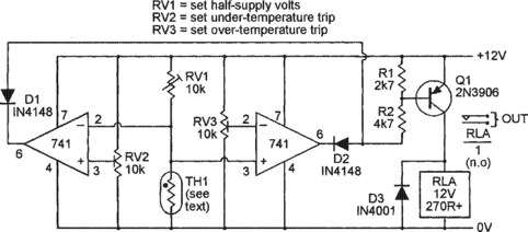
Both of these circuits are made by combining the basic over-temperature and under-temperature circuits of Figures 5.7 and 5.12. The right (over-temperature) half of each circuit is based on that of Figure 5.7, and the left (under-temperature) half is based on that of Figure 5.12. Both halves of the circuit share a common RV1–TH1 temperature-sensing network, but the under-temperature and over-temperature switching levels of the circuits are independently adjustable. Each of the two op-amp outputs of the Figure 5.17 circuit are taken to independent transistor-relay output stages, while the two op-amp outputs of the Figure 5.18 circuit are taken to a single transistor-relay output stage via the D1–D2 gate network. The procedure for setting up the two circuits is as follows.
First, set RV2 and RV3 to roughly mid-travel, then, with TH1 at its normal or mid-band temperature, adjust RV1 so that half-supply volts are developed across TH1. Now fully rotate the RV2 slider towards the positive supply line, rotate the RV3 slider towards the zero volts line, and check that no ‘trip’ condition is indicated (relays off). Next, reduce the TH1 temperature to the required under-temperature trip value and adjust RV2 so that the appropriate relay goes on to indicate the ‘trip’ condition. Now increase the TH1 temperature slightly and check that the relay turns off. Finally, raise the TH1 temperature to the required over-temperature trip level and adjust RV3 so that the appropriate relay turns on to indicate the ‘trip’ condition. All adjustments are then complete, and the circuits are ready for use.
Figure 5.19 shows the circuit of a differential-temperature switch that activates a relay if two monitored temperatures differ by more than a preset amount. The circuit uses a pair of silicon diodes as temperature-sensing elements, and activates the relay only when the temperature of D1 is more than a pre-set amount greater than that of D2, and is not influenced by the absolute temperatures of the two diodes. Circuit operation is as follows.
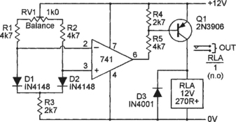
General-purpose silicon diodes D1 and D2 are used as temperature-sensing elements. A standing current is passed through D1 from the positive supply rail via RV1–R1 and R3, and a similar current is passed through D2 via RV1–R2 and R3. The relative values of these currents can be adjusted over a limited range via RV1, thus enabling the forward volt drops of the diodes to be equalized, so that they give zero differential output when they are both at the same temperature.
Suppose then that the diode voltages have been equalized in this way, so that zero voltage differential exists between them. If now the temperatures of both diodes are raised by 10°C, the forward voltages of both diodes will fall by 20mV, and zero differential will still exist between them. The circuit is thus not influenced by identical changes in the temperatures of D1 and D2.
Suppose next that the temperature of D2 falls 1°C below that of D1; in this case the D2 voltage will rise 2mV above that of D1, so the op-amp’s pin-3 voltage goes positive to that of pin-2, thus driving the op-amp output to positive saturation and holding Q1 and the relay off. Finally, suppose that the temperature of D2 rises 1°C above that of D1; in this case the D2 voltage will fall 2mV below that of D1, so the op-amp output goes into negative saturation and drives Q1 and the relay on. Thus, the relay turns on only when the temperature of D2 is above that of D1. The circuit has a typical sensitivity of 0.5°C
The above explanation assumes that RV1 is adjusted so that the D1 and D2 voltages are exactly equalized when the two diodes are at the same temperature, so that the relay goes on when the D2 temperature rises a fraction of a degree above that of D1. In practice, RV1 is usually adjusted so that the standing bias voltage of D2 is some millivolts greater than that of D1 at normal temperatures, in which case the relay will not turn on until the temperature of D2 rises some way above that of D1. The magnitude of this differential temperature trip level is fully variable from zero to about 10°C via RV1, so the circuit is quite versatile. The circuit can be set up by raising the temperature of D2 the required amount above that of D1, and then trimming RV1 so that the relay just turns on under this condition.
Precision temperature sensor ICs
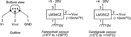
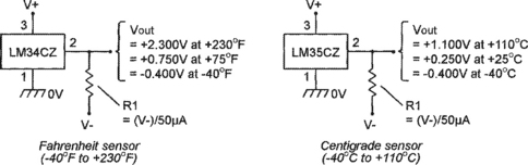
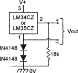
Several companies manufacture dedicated temperature-sensing ICs that are suitable for use in place of ordinary silicon diodes in high-precision security applications. Two of the most useful and popular of these ICs are National Semiconductor’s commercial-grade LM34CZ and LM35CZ micropower temperature sensors, which are each housed in 3-pin TO-92 packages and produce output voltages that are linearly equal to +10mV/°F and +10mV/°C respectively. Figure 5.20 lists the basic specifications of these two ICs, and Figure 5.21 shows the IC outline and pin notations of the ICs, together with their basic application circuits.

Note in the Figure 5.21 basic application circuits that – since the circuits use single-ended supplies and the ICs give output voltages that are directly proportional to temperature – these simple designs cannot indicate temperatures that are below zero (in practice, the simple LM34CZ circuit can accurately indicate temperatures down to only +5°F, and the LM35CZ can indicate minimum temperatures of +2°C). If required, the ICs can be made to give full-range outputs (i.e. to give temperature readings down to −40°F or −40°C) by using the dual-supply connections shown in Figure 5.22, or by using the single-ended ‘simulated dual-supply’ connection of Figure 5.23.
Also note that – like most micropower ICs – these devices tend to become unstable if their outputs are fed directly to uncompensated capacitive loads greater than a few picofarads. This snag can be overcome by feeding such loads in either of the ways shown in Figure 5.24. Finally, note that these ICs can be used to make analogue thermometers by connecting their outputs to a 100μA moving-coil meter via a suitable ‘ranging’ resistor, using the connections shown in Figure 5.25; this ranging resistor needs an actual value equal to the desired full-scale temperature (in degrees) multiplied by 100R, minus the meter’s coil resistance. Thus, to read 120°F full-scale, using a meter with a coil resistance of 3750 ohm, the multiplier needs a resistance of 12k – 3.75k = 8.25k.

