Security system basics
Any system that provides its owner/user with a reasonable degree of protection against one or more real or imagined dangers, threats, or nuisances (such as physical attack, theft of property, unwanted human or animal intrusion, machine breakdown, or risks from fire, electric shock, or vermin infestation, etc.) can be described as a ‘security’ system. An ‘electronic’ security system is one in which the system’s actions are heavily dependent on electronic circuitry; simple examples of such systems are electronic door-bells, key-pad door locks, and domestic burglar alarms. The opening chapter of this book starts off by explaining electronic security system basic principles and then goes on to describe a wide variety of devices that can be used within modern electronic security systems. Later chapters show practical examples of various specific types of low- to medium-complexity electronic security systems and circuits.
Electronic security system basics
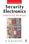
All electronic security systems consist of the basic elements shown in Figure 1.1. Here, one or more ‘danger’ sensing units are placed at the front of the system and generate some kind of electrical output when danger is sensed. The output of the sensor unit is fed, via a data link, to a decision-making signal processing unit, and this unit’s output is fed, via another data link, to a ‘danger’ response unit such as an alarm or an electromechanical trigger or shutdown device. Note in Figure 1.1 that each of the system’s three major elements is shown using its own power supply, but that in practice two or more elements may share a single power supply.
Figures 1.2 to 1.5 show, in basic form, four different low- to medium-complexity types of security system. The first of these (Figure 1.2) is a simple electronic door-bell or shop-entry alarm system, in which the ‘danger’ sensor is a push-button switch in the case of the door-bell system or a door-mounted microswitch (or a pressure mat switch, etc.) in the case of the shop-entry system. In both cases, the circuit action is such that when switch S1 closes it activates a timing generator that turns on an alarm sound generator for a period of 10 seconds, irrespective of the actual duration of the switch closure, and repeats this action each time that S1 is closed. Ideally, this type of circuit draws zero quiescent current. Note in the case of the door-bell circuit that the ‘danger’ sensor (S1) is operated voluntarily by the unknown visitor, in a deliberate effort to attract the attention of the householder, but that in the case of the shop-entry circuit S1 is operated involuntarily by the visitor, and warns the shopkeeper of the presence of a potential customer or thief.

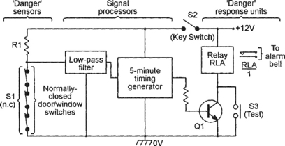
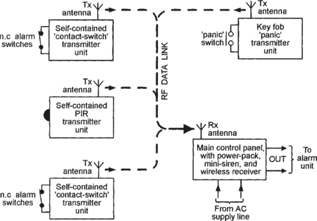
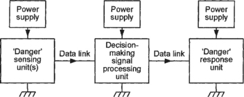
Figure 1.3 shows a simple domestic burglar alarm circuit. Here, the main alarm system is enabled by closing key-operated switch S2, and the S1 ‘danger’ sensor actually consists of any desired number of series-connected normally-closed switches (usually reed-and-magnet types) that are each wired to a protected door or window, so that the composite S1 switch opens when any protected door or window is opened or a break occurs in S1’s wiring. Under this condition, R1 pulls the input of the transient-suppressing low-pass filter high, and after a brief delay (usually about 200mS) the filter output triggers the 5-minutes timer generator, which turns on relay RLA via transistor Q1 and thereby activates an external alarm bell or siren via the relay’s RLA/1 contacts. Once activated, the relay and alarm turn off automatically at the end of the 5-minute timing period, but can be turned off or reset at any time by opening key-switch S2. The alarm can be tested at any time, with or without closing S2, via push-button switch S3, which closes RLA directly.
Figure 1.4 shows, in pictorial form, a modern passive infra-red (PIR) movement detector system that can be used to automatically sound an alarm or turn on floodlights when a person enters the PIR detection field (the PIR has a typical maximum range of 12 metres and the field has a vertical span of about 15 degrees and a horizontal span of 90 to 180 degrees). The PIR unit detects the small amounts of infra-red radiation generated by human body heat, but gives an ‘alarm’ output only when the heat source moves significantly within the detection field. Most PIR units have good immunity to false alarms; some types incorporate an output relay that is normally closed (turned on) but opens (turns off) when an intruder is detected or the unit’s power supply fails or is removed; units of this latter type typically need a 12V DC supply and consume a quiescent current of about 20mA. PIR units are widely used to give room or area protection in modern burglar alarm systems.
Figure 1.5 shows, in simplified form, the basic elements of a modern domestic ‘wireless’ burglar alarm system, in which the data link between the various major parts of the system takes the form of a coded RF (usually 418MHz or 458MHz) signal, thus greatly easing installation problems. The heart of the system is the main control panel, which houses a wireless receiver and decoder and control logic, plus a high-power mini-siren, and has an output that can activate an external high-power siren and light-strobe alarm unit. The system’s ‘danger’ sensing units each house a small RF transmitter and antenna that sends out a coded signal under a danger condition; each of the units are designed to give a minimum of six months of normal operation from a small battery.
Most domestic wireless burglar alarm systems can be used to monitor a maximum of four to six zones (individual protected areas) via suitable sensing units. The sensing units come in three basic types; ‘contact-switch’ types transmit a danger signal when one or more series-connected normally-closed switches are opened, and can be used to protect a zone of any desired size; ‘PIR’ types transmit a danger signal when a human moves within the visual field of the PIR unit, and can be used to protect a zone of limited size; ‘panic’ types transmit a danger signal when a key-fob button is pressed, and can be used to protect a person against sudden physical attack or threat whenever they are within communication range of the system’s receiver (control panel) unit. All three types of sensing unit also send out monitoring signals that give warnings of failing battery power or deliberate interference, etc., and the wireless burglar alarm system thus offers a high degree of security.
Note that simple electronic security systems such as those shown in Figures 1.2 and 1.3 can be easily and cheaply built on a DIY basis, but that it is not cost-effective to build a PIR unit of the Figure 1.4 type as a DIY project, or cost-effective or legal (because the RF transmitters must be certified by an approved state or national body) to build (rather than buy) a Figure 1.5 type of wireless burglar alarm system as a pure DIY project. Commercial PIR units and wireless burglar alarm units can, however, easily be used as special elements that can be incorporated in a wide variety of DIY security systems.
Security system reliability
The most important parameter of any practical electronic security system is its reliability in performing its designated task. Specifically, all such systems must be easy to use, difficult to disable, and have good immunity against malfunctioning and the generation of false alarms (which very quickly destroy the user’s confidence in the system). The degree and types of reliability required from a security system vary with the level of security that the system is designed to provide. Domestic burglar alarm systems (in which only a few family members have access to the major functional parts of the system) have, for example, relatively low anti-tamper requirements, but anti-burglary systems used in large shops and stores – in which the public have easy access to many protected areas during normal ‘opening’ hours – have very high levels of anti-tamper requirement.
The overall reliability of any electronic security system is greatly influenced by the nature of its major system elements, i.e. by its danger sensing units and its data links, etc. Simple electromechanical danger sensors such as reed switches and pressure pad switches have, for example, far greater intrinsic levels of reliability than electronic sensors such as ultrasonic, microwave, and simple light-beam intrusion detectors, but electronic key-pad security switches usually have far greater reliability than the mechanical key-switches that they are designed to replace, and so on. To gain a useful insight into this subject, the reader needs a good understanding of the wide variety of elements that are used in modern electronic security systems.
Security system elements
All electronic security systems consist – as shown in Figure 1.1 – of one or more ‘danger’ sensing units that generate some kind of electrical output when danger is sensed, and which feed that output – via a data link and a decision-making signal processing unit – to a ‘danger’ response unit such as an alarm or an electromechanical trigger or shutdown device. Apart from the actual signal processing unit, the three other major elements of any electronic security system are thus the sensing unit, the data link, and the response unit, and each of these elements may take an electromechanical, electrical, or an electronic form. Each of these three basic elements are available in a variety of guises, and the most important of these are described in the remaining sections of this chapter.
Electromechanical sensors
The simplest and most widely used electromechanical sensors are ordinary electrical switches of the various types shown in Figures 1.6(a) to 1.6(e). The types shown in (a) to (d) are linear pressure-operated types and may take normal manually-operated forms or may be microswitches that are activated by the mechanical movement of a door, window or machine part, etc. The (e) type is a rotary multi-step pressure-operated switch that is (normally) activated manually. The sensor shown in (a) is a normally-open (NO or n.o.) push-button switch, (b) is a normally-closed (NC or n.c.) push-button switch, (c) is a single-throw single-pole (SPST) toggle switch, (d) is a single-pole double-throw (SPDT) or ‘change-over’ toggle switch, and (e) is a single-pole 4-way rotary switch.

Figure 1.7 shows three basic ways of using normal electrical switches in power (or signal) switching applications. In (a), a SPST switch is used as an on/off controller to switch power to a single load, in (b) a 1-pole 3-way switch is used as a power distributor to switch power to any one of three loads, and in (c) is used as a power selector, to connect any one of three power sources to a single load.

Switched-output electromechanical sensors are available in a variety of basic types, including temperature-sensitive thermostats, orientation-sensitive ‘tilt’ and ‘tip-over’ switches, pressure-sensitive ‘mat’ switches, key-operated security switches, and time-sensitive ‘timer’ switches, all of which are shown in basic form in Figures 1.8 to 1.10.

Thermostats
Thermostats are temperature-activated on/off switches that usually work on the ‘bimetal’ principle illustrated in Figure 1.8(a), in which the bimetal strip consists of two bonded layers of conductive metal with different coefficients of thermal expansion, thus causing the strip to bend in proportion to temperature and to make (or break) physical and electrical contact with a fixed switch contact at a specific temperature. In practice, the bimetal element may be in strip, coiled, or snap-action conical disc form, depending on the application, and the thermal ‘trip’ point may or may not be adjustable. Figures 1.8(b) and (c) show the symbols used to represent fixed and variable thermostats. A variety of thermostats are readily available, and can easily be used in automatic temperature control or danger-warning (fire or frost) applications. Their main disadvantage is that they suffer from hysteresis; typically, a good quality adjusted thermostat may close when the temperature rises to (say) 21°C but not re-open again until it falls to 19.5°C.
Tilt switches
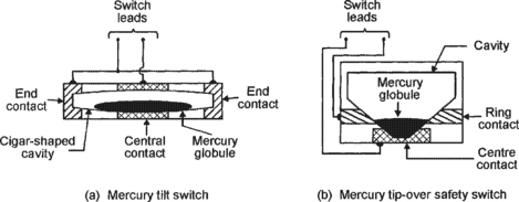
Figure 1.9(a) illustrates the basic construction and operating principle of a mercury tilt switch, which (in this example) consists of a cigar-shaped cavity that is formed within a block made of two electrically-connected metal end contacts and a central metal contact, which are separated by insulating sections. The cavity holds a mercury globule, which rests on the central contact but is insulated from the end contacts when the switch is horizontal, but rolls and touches one or other of the end contacts (and also the central contact) if the switch is tilted significantly (typically by more that 10 degrees) out of the horizontal. The mercury ‘switch’ is thus normally open, but closes when tilted, and can be used to activate an alarm if an attempt is made to move a normally-stationary protected item such as a TV, PC, or hi-fi unit, etc.
Tip-over switches
Figure 1.9(b) illustrates the basic construction and operating principle of a mercury tip-over safety switch. In this case the cavity is fairly steep-sided, and the construction is such that the mercury globule touches both a ring contact and a centre contact when the unit is vertical, and thus acts as a closed switch, but breaks this contact and acts as an open switch when the unit is tilted heavily (typically by more than 40 degrees) out of the vertical position. One common application of this type of switch is in free-standing electric heaters, where the switch is built into the unit and wired in series with its power lead, so that the appliance automatically turns off if it is accidentally knocked over.
Pressure mat switches
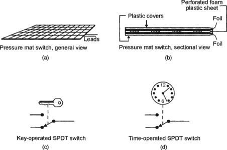
Figures 1.10(a) and 1.10(b) illustrate the general appearance and basic construction of a pressure mat switch, which is designed to be hidden under a mat or carpet and acts as a normally-open switch that closes if a person steps heavily on any part of the switch. The device consists of two sheets of metal foil that are normally held apart by a perforated sheet of foam plastic; this sandwich is encased in a hermetically sealed plastic envelope; when a person treads on the envelope their weight compresses the foam plastic, and the metal foils make electrical contact via the foam sheet’s perforations. Pressure mat switches are widely used in domestic and commercial burglar alarm systems; most such switches have four output wires; the two ‘switch’ wires have partly-bared ends; the other two wires are not bared, are internally shorted together, and serve a n.c anti-tamper function in which an alarm system activates if the sensor wiring is cut (see the Data links section of this chapter), and can be ignored in most domestic applications.
Key switches
Figure 1.10(c) shows a symbolic representation of a simple key-operated SPST electric switch, in which the switch arm is moved by turning a Yale-type key in a matching tumbler mechanism. Switches of this basic type are available in many different switch and key-type styles, and are widely used in security applications in buildings and vehicles, and on items such as PCs and burglar alarm control units. The most important parameter of a key-switch (or of any type of key-operated lock) is its number of ‘differs’ or possible key profiles; Yale-type switches have a number of pins (usually five) which must each be raised to a certain level by the key to allow the switch to operate; usually, each pin has three possible levels, and a simple 5-pin key switch thus has 243 (= 35) differs; if the key’s shaft also carries two long grooves that must match the lock’s face plate and offer (say) a further 9 differs, the total number of differs is raised to 2187.
Time switches
Figure 1.10(d) shows a symbolic representation of a simple analogue time-operated SPST electric switch, in which the switch arm is moved by a mechanical (clockwork or slow-release), electrical (current-heated thermostat) or electromechanical (synchronous motor plus gearbox) timing mechanism. Switches of this basic type are available in many different switch styles, with many different timing ranges, and are widely used in light-switching and solenoid-operating security applications.
Reed switches
One of the most useful types of switched-output electromechanical sensor devices is the ‘reed’ switch, which activates in the presence of a suitable magnetic field and is particularly useful in proximity-detector applications. Figure 1.11 shows the basic structure of a reed switch, which consists of a springy pair of opposite-polarity magnetic reeds with plated low-resistance contacts, sealed into a glass tube filled with protective gasses. The opposing magnetic fields of the reeds normally hold their contacts apart, so they act as an open switch, but these fields can by nulled or reversed by placing the reeds within an externally-generated magnetic field (see Figure 1.12), so that the reed then acts as a closed switch.

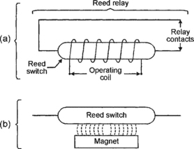
A reed switch can be activated by placing its reeds within an externally-generated magnetic field, which can be derived from either an electric coil that surrounds the glass tube, as in the ‘reed relay’ diagram of Figure 1.12(a), or by a permanent magnet placed within a few millimetres of the tube, as shown in Figure 1.12(b). Reed relays are used in the same way as normal relays, but typically have a drive-current sensitivity ten times better than a standard relay. Reed-and-magnet combinations are very useful in proximity-detector applications in security and safety systems, etc., as illustrated in Figure 1.13.
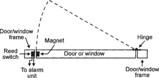
Figure 1.13 Method of using a reed switch/magnet combination to give burglar protection to a door or window
Figure 1.13 shows a method of using a reed and magnet to give burglar protection to a door or window. Here, the reed switch is embedded in a door or window frame, and the activating magnet is embedded adjacent to it in the actual door or window so that the reed switch changes state whenever the door/window is opened or closed. The reed switch can thus be used to activate an alarm circuit whenever a protected door/window is opened. In practice, the reed and magnet may take the basic forms shown in Figure 1.12(b), or may be encapsulated in special housings that can easily be screwed to – or embedded in – the frame/body of the door/window.
Basic alarm switching circuits
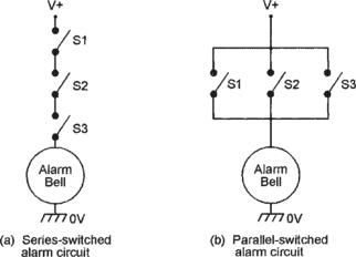
Several switched-output sensor devices can be used to activate an alarm bell or other device by connecting them in one or other of the basic modes shown in Figure 1.14. In (a), the switches are wired in series, so that the alarm sounds only when all three switches are closed at the same moment. In (b), the switches are wired in parallel, and the alarm sounds whenever any one of the switches is closed. In most practical alarm systems, a combination of series and parallel switching is used, as shown in the example of Figure 1.15. In this case, the alarm system is enabled (made alert) by closing series-connected time switch S1 and key switch S2; once enabled, the alarm bell can be activated by closing any of the parallel-connected S3 to S5 switches. In burglar alarm systems, important intrusion-sensing switches should be n.c.types that are wired in series and used in the basic manner already shown in Figure 1.3, so that the alarm activates if any switch opens or if its wires are cut; R1 should have a high value (typically several megohms), to give low quiescent current consumption.

Electrical sensor devices
A thermistor is a passive resistor device with a resistance value that is highly sensitive to the device’s temperature. Practical thermistors are available in rod, disc, and bead forms, and with either positive or negative temperature coefficients (known as PTC and NTC types respectively). Unlike electromechanical thermostats, they do not suffer from hysteresis problems, and are thus suitable for use in a variety of precision temperature sensing and switching applications. Figure 1.16 shows two alternative symbols that can be used to represent a thermistor. In most practical applications, thermistors are used in conjunction with electronic circuitry that gives a switch-type output when the thermistor temperature goes above (or below) a pre-set limit. Thermistors have typical operating temperature ranges of −40°C to +125°C.

Thermocouples
When a junction is formed between two dissimilar metals a thermo-electric (temperature-dependent) voltage is generated across the junction. Thermocouples are devices in which the two types of metal are specially chosen to exploit this effect for temperature measurement purposes. A thermocouple using a copper and copper-nickel junction, for example, has a useful ‘measurement’ range from −100°C to +250°C, and has a typical sensitivity of 42μV per °C over the positive part of that range. Some thermocouples using other types of metal have useful measurement ranges that extend well above +1100°C. Figure 1.17(a) shows the symbol used to denote a normal thermocouple. In some special types of thermo-couple device the junction can be heated via a d.c. or r.f. current passed through a pair of input terminals; the thermocouple output can then be used to indicate the magnitude of the input current or power. Devices of this type use the symbol shown in Figure 1.17(b).
Light-dependent resistors (LDRs)
An LDR (also known as a cadmium sulphide (CdS) photocell) is a passive device with a resistance that varies with visible-light intensity. Figure 1.18 shows the device’s circuit symbol and basic construction, which consists of a pair of metal film contacts separated by a snake-like track of light-sensitive cadmium sulphide film; the structure is housed in a clear plastic or resin case. LDRs have many practical applications in security and auto-control systems.
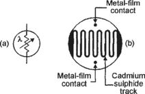
Figure 1.19 shows the typical photoresistive graph that applies to an LDR with a face diameter of about 10mm; the resistance may be several megohms under dark conditions, falling to about 900R at a light intensity of 100 Lux (typical of a well lit room) or about 30R at 8000 Lux (typical of bright sunlight).

Microphones
Microphones are acoustic-to-electrical transducers and have a number of uses in eavesdropping and other security applications. The three best known types of electrical microphones are the moving-coil (‘dynamic’), ribbon, and piezoelectric (‘crystal’) types. In most security electronics application, microphones are required to be small but sensitive types that generate medium-fidelity outputs; electronic ‘electret’ microphones are widely used in such applications.
Electronic sensor devices
An ‘electronic’ sensor may take the form of a single semiconductor component such as a photodiode or phototransistor, or may be a combination of electrical and/or electronic components that together perform a particular sensing function; examples of the latter type are electronic key-pad locks and light-beam alarms. The most important of such devices are described in this section.
Photodiodes
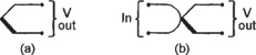
When p–n silicon junctions are reverse biased their leakage currents and impedances are inherently photo-sensitive; they act as very high impedances under dark conditions and as low impedances under bright ones. Normal diodes have their junctions shrouded in opaque material to inhibit this effect, but photodiodes are made to exploit it and use a translucent casing material; some photodiodes are made to respond to visible light, and some to infra-red (IR) light. Figure 1.20(a) shows the standard symbol of a photodiode. In use, the photodiode is simply reverse biased and the output voltage is taken from across a series resistor, which may be connected between the diode and ground as shown in Figure 1.20(b), or between the diode and the positive supply line, as in Figure 1.20(c).

Phototransistors
Ordinary silicon transistors are made from an npn or pnp sandwich, and thus inherently contain a pair of photo-sensitive junctions. Some types are available in phototransistor form, and use the standard symbol shown in Figure 1.21(a). Figures 1.21(b) to 1.21(d) show three basic ways of using a phototransistor; in each case the base-collector junction is effectively reverse biased and thus acts as a photodiode. In (b) the base is grounded, and the transistor acts as a simple photodiode. In (c) and (d) the base terminal is open circuit and the photo-generated currents effectively feed directly into the base and, by normal transistor action, generate a greatly amplified collector-to-emitter current that produces an output voltage across series resistor R1.
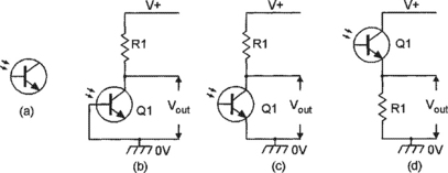
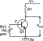
The sensitivity of a phototransistor is typically one hundred times greater than that of a photodiode, but its useful maximum operating frequency (a few hundred kHz) is proportionally lower than that of a photodiode (tens of MHz). Some phototransistors are made in very-high-gain Darlington form. A phototransistor’s sensitivity (and operating speed) can be made variable by wiring a variable resistor between its base and emitter, as shown in Figure 1.22; with RV1 open circuit, phototransistor operation is obtained; with RV1 short circuit, photodiode operation occurs.
Optocouplers
An optocoupler is a device housing a LED (usually an IR type) and a matching phototransistor; the two devices are optocoupled but are electrically isolated from each other and – in a normal type of optocoupler – are mounted in a light-excluding housing. Figure 1.23 shows a basic optocoupler ‘usage’ circuit. The LED is used as the input side of the circuit, and the phototransistor as the output. Normally, SW1 is open and the LED and Q1 are thus off. When S1 is closed a current flows through the LED via R1, and Q1 is turned on optically and generates an output voltage across R2. The output circuit is thus controlled by the input one, but the two circuits are fully isolated electrically (‘isolation’ is the major feature of this type of optocoupler, which can be used to couple either digital or analogue signals).

The Figure 1.23 device is a standard type of optocoupler. There are, however, two special types of optocoupler that are of particular value in security electronics applications, and these are shown in Figures 1.24 and 1.25. The Figure 1.24 ‘slotted’ device has a slot moulded into the package between the LED light source and the Q1 light sensor. Light can normally pass from the LED to Q1 via a pair of windows in the slot walls, but can be blocked by placing an opaque object in the slot. The slotted optocoupler can thus be used in a variety of ‘presence detecting’ applications, such as limit switching and dark-liquid level detection.


The Figure 1.25 ‘reflective’ optocoupler has the LED and the Q1–Q2 Darlington light sensor optically screened from each other within the package but arranged so that they both point outwards – via windows – towards an external point. The construction is such that an optocoupled link can be set up by a reflective object (such as metallic paint or tape) placed a short distance outside the package, in line with the LED and Q1. The reflective optocoupler can thus be used in applications such as tape-position detection, engine- or motor-shaft RPM measurement, or marked-object theft (illegal movement) detection, etc.
Light-beam units
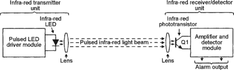
Most modern ‘light-beam’ units work on the basic principle illustrated in Figure 1.26, in which a focused invisible beam of pulsed infra-red light is generated by a transmitter unit, and is detected at a remote point by a matching lens and receiver/detector unit. Normally, the unit is configured so that the receiver generates an alarm output if the IR beam is interrupted. Such units have useful operating ranges of up to thirty metres and are often used in industry in automatic batch counting and safety-switch operating applications, and in commercial and domestic applications as intruder-detecting security alarms. Simple single-beam alarms of the basic Figure 1.26 type have fairly low values of reliability, since they can easily be triggered by insects settling on one or other of the unit’s lenses, but dual-beam types of alarm – in which both the transmitter and the receiver use two lenses placed a few inches apart – have high values of reliability.
Pyroelectric IR detectors
Some special crystals and ceramics generate electric charges when subjected to thermal variations or uneven heating; this is known as a pyroelectric effect. Pyroelectric infra-red detectors incorporate one or two elements of this type, plus a simple filtering lens and a field-effect transistor (FET), configured in the basic way shown in Figure 1.27(a). The basic action of the device is such that – if a human body moves within the visual field of its pyroelectric elements – part of the radiated infra-red energy of that body falls on the surface of the elements and is converted into a minute variation in surface temperature and a corresponding variation in the element’s output voltage. When the unit is wired as shown in the Figure 1.27(b) basic usage circuit, this movement-inspired voltage variation is made externally available via the buffering JFET and capacitor C1 and can, when suitably amplified and filtered, be used to activate an alarm when a human body movement is detected.
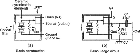
Note that pyroelectric IR detector circuits of the basic type described above have, because of the small size of the detector’s light-gathering lens, maximum useful detection ranges of just over one metre, but that this range can be extended to more than ten metres with the aid of a relatively large external light-gathering/focusing lens of the type used in modern passive infra-red (PIR) movement detector systems (see Figure 1.4 and its associated text).
Piezoelectric transducers
A piezoelectric transducer is an electro-constrictive device that converts a varying electrical signal into a sympathetic set of fine mechanical variations, or vice versa. Devices of this type include piezo sounders, ‘crystal’ earphones and microphones, ordinary quartz crystals, and ultrasonic transducers. Most devices of the later type are sharply tuned low-power units designed to peak at about 40kHz, and are supplied in matching pairs, with one optimized for use as a signal transmitter and the other as a signal receiver. They are useful in many remote control and distance-measurement applications, and in ‘doppler effect’ intruder alarm systems of the basic type shown in Figure 1.28.

The Figure 1.28 intruder alarm system consists of three main elements. The first is a transmitter (Tx) that floods the room with 40kHz ultrasonic signals, which bounce back and forth around the room. The second is a receiver (Rx) that picks up and amplifies the reflected signals and passes them to a phase comparator, where they are compared with the original 40kHz signal. If nothing is moving in the room the Tx and Rx signal frequencies will be the same, but if an object (an intruder) is moving in the room the Rx signal is doppler-shifted by an amount proportional to the rate of object movement (by about 66Hz at 10 inches/sec). The l.f. output of the comparator is passed on to the third system element, the alarm activator, which is a signal conditioner that rejects spurious and out-of-limits signals, etc., and activates the alarm-call generator only if an intruder is reckoned to be genuinely present. In practice, many systems of this basic type have poor reliability when set to high-sensitivity levels, since they can easily be false-triggered by draughts, central-heating air currents, and curtain movements, etc. Low-sensitivity versions of the system are often used to protect small areas, such as the interiors of automobiles, however, and usually have high values of reliability.
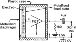
Electret microphones
Electret microphones are modern highly efficient ‘capacitor’ microphones, and use the basic form of construction shown in Figure 1.29. Here, a light-weight metallized diaphragm forms one plate of a capacitor, and the other plate is fixed and is metallized on to the back of a slab of insulating material known as electret; the capacitance value thus varies in sympathy with the applied acoustic (sound) signal. The electret material holds a fixed electrostatic charge that is built in during manufacture and can be held for an estimated 100-plus years; this charge is applied between the two plates. The voltage across the capacitor equals this charge divided by the capacitance value and – since this varies in sympathy with the applied acoustic signal – varies in sympathy with the acoustic signal. This signal is fed to the outside world via a built-in IGFET transistor, which needs to be powered externally from a battery (1.5V to about 9V) via a 1k0 resistor, as shown. Electret microphones are robust and inexpensive and give a good performance up to about 10kHz; they are useful in many audio sound pick-up applications, particularly in sound-activated alarms and eavesdropping units.
Key-pad switches
These are modern and greatly superior replacements for conventional electromechanical key-switches, and are opened by typing a secret multi-digit code number into a simple key-pad, rather than by the use of an easily lost or stolen mechanical key. Typically, units of this type take the basic form shown in Figure 1.30, in which the key-pad houses twelve push-button switches, notated with the numerals 0 to 9 and the letters C (change code) and D (disable/enable), plus two state-indicating LEDs. The switches are (in this example) arranged in four vertical and three horizontal columns, which are wired to a clocked decoder and control logic network that converts each digit keystroke into a 4-bit binary code and compares it with the 4-bit code that is stored in the matching line of the system’s RAM; if the entire code number (which is usually 4 to 8 digits long) is typed in without error, the switch opens and performs a useful function (opens a door or gives access to an engine’s start-up system, etc.), but if the correct code is not entered within three attempts the lock automatically goes into a time-controlled shutdown or alarm mode.
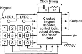
In the above system, the secret code number can be changed at any time by simply typing in the existing code, pressing the ‘C’ switch once (to gain direct access to the RAM), typing in the new code number, and then pressing the ‘C’ switch again (to return to normal operation). The entire keyswitch can be disabled (for a time-controlled period) or re-enabled at any time by operating the ‘D’ switch, which gives a toggling disable/enable type of action; the key-pad switch’s operating mode is displayed at all times via the two state-indicating LEDs.
Digital time switches
Figure 1.31 shows a symbolic representation of a digital time-operated SPST electric switch, in which the switch arm is controlled via accurately timed digital circuitry and can be programmed to turn on and off at any desired times of the day or week. Digital time switches offer far greater precision than normal analogue types, and are used in many light-switching and solenoid-operating security applications.

Miscellaneous electronic sensors
A variety of special-purpose electronic sensors of value in security applications but not so-far mentioned in this section are also available from some specialist dealers. Among the most useful of these are radioactive ‘smoke detector’ elements that respond to various ionized particles, humidity sensors, strain gauges, hall-effect devices that respond to magnetic field strength (flux density), and ‘gas’ sensors that react to gases such as propane, butane, methane, isobutane, petroleum gas, natural gas, and ‘town’ gas. A few of these devices are described in some detail in later chapters of this volume.
Data links
Data links are (apart from the actual signal processing unit) one of the three major elements of any electronic security system, the other two elements being the sensing unit(s) and the response unit. All practical security systems use at least two data links (see Figure 1.1), which may have individual lengths ranging from less than one millimetre to many thousands of kilometres, depending on the specific application. Most data links fit into one or other of three basic types, being either hard-wired types, optocoupled types, or wireless types, as described in the rest of this Data links section.
Hard-wired data links
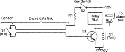
Most hard-wired data links take the form of a length of multi-cored cable, used to link a sensor or response unit to the alarm system’s main control unit. Figures 1.32 to 1.34 show examples of such cables used to link a sensor switch to the input of a simple burglar alarm unit. In Figure 1.32 the sensor switch is a normally-closed one of the type used to protect doors or windows and is connected to the unit via a 2-wire (or 2-core) data link; this circuit’s basic action is such that – when key-switch S2 is closed – Q1 and the alarm both turn on if sensor switch S1 is opened or the data link is accidentally or deliberately cut; this circuit thus has an inherently good anti-tamper performance.

In the Figure 1.33 circuit the sensor switch is a normally-open type such as a pressure mat switch, and is connected to the unit via a 2-wire data link; this circuits basic action is such that – when key-switch S2 is closed – Q1 and the alarm normally both turn on if sensor switch S1 is closed, but will fail to operate if the data link is accidentally or deliberately cut; this circuit thus has a poor anti-tamper performance.
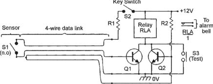
Finally, Figure 1.34 shows a high-security version of the above circuit. In this case the sensor switch is again a normally-open type such as a pressure mat switch, but is connected to the unit via a data link that uses four wires, two of which serve an anti-tamper function; this circuit’s basic action is such that the alarm normally turns on via R1–Q1 if sensor switch S1 and key-switch S2 are both closed, but operates instantly (even if key-switch S2 is open) via Q2-R2 if the 4-wire data link is accidentally or deliberately severed; this circuit thus has an excellent anti-tamper performance and is often used in department stores and other places in which the public have easy access to parts of the alarm system.
Optocoupled data links
Optocoupled data links are often used in applications where it is not possible or convenient to use a hard-wired data link, and come in three basic types, being either infra-red ‘light-beam’ types, fibre optic ‘light guide’ types, or laser beam types. Light-beam types are used mainly in short-range (less than 6 metres) remote control applications, but can – if used with a good lens system – be effective at ranges up to about 20 metres; units of the latter type are sometimes used (in domestic applications) as a data link between a shed or other remote building’s intrusion sensor and a main alarm unit. Fibre optic light guide data links are used mainly in applications where the link is fairly long (greater than ten metres) and needs a wide signal bandwidth. Laser beam data links are used mainly in medium-range applications in which a hard-wired link can not be used; they are sometimes used (illegally) in remote eavesdropping applications, in which the beam is bounced off the window of a room in which a secret conversation is taking place, the return beam being modulated by the window’s acoustic pick-up signals.
Wireless data links
Wireless data links – usually operating at 418MHz or 458MHz – are widely used in modern domestic burglar alarm systems (see Figure 1.5) to link the system’s various sensors to the main control unit, thus greatly easing installation problems and enabling the system to be remote-controlled via a small key-fob signal transmitter. Most systems of this type have typical control ranges of up to 30 metres, but some sophisticated systems can be interfaced with both the domestic heating control unit and with the normal telephone system, enabling alarm and heating systems to be remotely monitored or controlled over a range of thousands of miles. The owner of such a system can, while holidaying or working abroad, use a fixed or mobile phone to check the home’s security at any time, or can use it to remotely turn on the building’s central heating system prior to eventually returning home.
Alarm response units
Alarm response units are the final major elements in any electronic security system, and usually take the form of a simple relay, some type of electromagnet, a solenoid- or motor-operated mechanism, or (in burglar alarm and other high-level security systems) a sound generator and/or a light strobe unit; brief details of units of these types are given in the rest of this Alarm response units section.
Relay response units
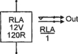
Relays are electrically operated switches that can be used to activate virtually any external electrical devices (such as lamps, sirens, motors, etc.). Relays come in two basic types, one being the ‘reed’ type that has already been shown in Figure 1.12(a) and the other being the conventional electromagnetic type that takes the basic form shown in Figure 1.35. Here, a multi-turn coil is wound on an iron core to form an electromagnet that can move an iron lever or armature which in turn can close or open one or more sets of switch contacts. The operating coil (which requires only a modest operating current) is electrically fully isolated from the switch contacts (which can control fairly high currents), and can be shown as separate elements in circuit diagrams, as shown in Figure 1.36, which represents a relay with a 12V, 120R coil and a single set of normally-open (n.o.) switch contacts.

Relays with a single set of n.o contacts are usually used in the basic non-latching mode shown in Figure 1.37(a), in which the relay closes when S1 is closed and opens when S1 is opened. Relays with two (or more) sets of n.o. contacts can also be used in the self-latching mode shown in Figure 1.37(b), in which n.o. contacts RLA/2 are wired in parallel with S1 so that they close and lock (latch) the relay on as soon as S1 is closed; once the relay has locked on it can be turned off again by briefly breaking the supply connections to the relay coil.

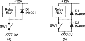
Relay coils are highly inductive and may generate back-emfs of hundreds of volts if their coil currents are suddenly interrupted. These back-emfs can easily damage switch contact or solid-state devices connected to the coil, and it is thus often necessary to ‘damp’ them via protective diodes, as shown in Figures 1.38. In Figure 1.38(a) the coil damping is provided via D1, which prevents switch-off back-emfs from driving the RLA–SW1 junction more than 600mV above the positive supply line. This form of protection is adequate for normal switching applications. In Figure 1.38(b) the damping is provided via two diodes that stop the RLA-SW1 junction swinging more than 600mV above the positive supply rail or below the zero-volts rail. This form of protection is recommended for all applications in which SW1 is replaced by a transistor or other solid-state switching device.
Electromagnet units
Electromagnet units are widely used in industrial and commercial applications to control the hold or release actions of security doors and safety guards and gates, etc. Figure 1.39 illustrates basic electromagnet operating principles. When a current is passed through a wire, a magnetic field is generated about the axis of the wire, as shown in the cross-sectional view in Figure 1.39(a). When such a wire is wound as a coil on an iron-cored former, the fields of the individual turns interact in the way shown in Figure 1.39(b), causing the core to act like a normal bar magnet (with north and south poles) when the coil is energized, but to act like a piece of non-magnetic iron when the coil is not energized. This basic type of electromagnet is thus used in energize-to-hold applications.
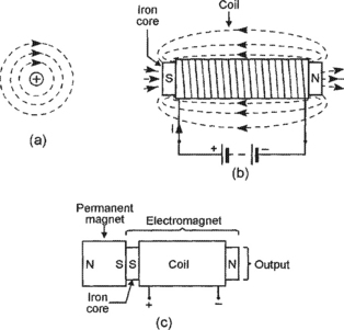
Figure 1.39 Diagrams showing the magnetic fields generated by (a) a current-carrying wire and (b) an electromagnet, and the basic construction of (c) an energize-to-release type of holding magnet
Figure 1.39(c) shows a useful variant of the normal electromagnet. Here, a permanent magnet is fixed to one end of the electromagnet’s iron core, in the polarity shown in the diagram, and the other end of the core forms the output of the unit. When the electromagnet is not energized, its iron core acts as a simple extension of the permanent magnet, with its output acting as the southern pole of the magnet, but when the electromagnet is energized its magnetic field opposes that of the permanent magnet, and (if the two opposing fields are of equal strength) the unit’s output is thus demagnetized. This type of unit thus acts as an energize-to-release type of holding magnet.
Solenoid-operated units
Solenoids are electromagnetic devices that are designed to move an iron ram or an armature and thereby activate a device such as a power switch, a safety latch, or a control valve or tap, etc. They consist of a multi-turn coil that is wound about the axis of a fixed or moving iron core. Fixed-core types act as simple electromagnets that move an external iron armature when the coil is energized; the best known example of this type of unit is the standard electromagnetic relay shown in Figure 1.35. In moving-core types of solenoid the coil is wound on a plastic or waxed-paper tube in which the iron core (which usually takes the form of a ram) is free to move; the basic action of this type of unit is such that the centre-of-mass of the iron core (ram) is forced into a central position within the coil when the coil is energized, but may be forced into a different position (via a spring, etc.) when the coil is not energized.
Moving-core solenoids come in several basic variants, and the three most widely used of these are shown in Figure 1.40. The most widely used type gives a simple linear movement of the ram, as shown in Figure 1.40(a). Here, the ram is normally biased to the left-of-centre of the coil by two collars and a spring, but is forced to the right (to the coil’s central position) when the coil is energized, thus giving a thrust action at the right-hand end of the ram and a pull action at the left-hand end; many practical solenoids of this basic type are designed to give only a thrust action or only a pull action.

Figure 1.40 Simplified diagrams of (a) a conventional moving-core linear solenoid, (b) a magnetically latching split-coil moving-core linear solenoid, and (c) a rotary solenoid
A useful variant of the moving-core linear solenoid is the magnetically latching split-coil type shown in Figure 1.40(b). Here, when a pulse of energizing current is fed to the right-hand (RH) side of the split coil, the ram is forced to the right until a machined collar makes contact with a fixed ring magnet, which latches the ram in that position when the coil is de-energized. Once the ram has latched into this position it can only be unlatched by feeding a pulse of energizing current to the left-hand (LH) side of the coil, thus forcing the ram to the left until its left face makes contact with a fixed disc magnet, which latches the ram into this alternative position, and so on. Magnetically latching solenoids are useful where low mean power consumption is required. Note that simple split-coil solenoids are widely used as points-controllers in model railway systems, but do not incorporate magnetic latching.
Finally, the third type of moving-core solenoid is the rotary movement type shown in Figure 1.40(c), in which the solenoid’s linear action is converted into rotary form via a simple crank or link mechanism. These units typically give maximum shaft rotation angles in the range 45° to 95°.
Bells and buzzers
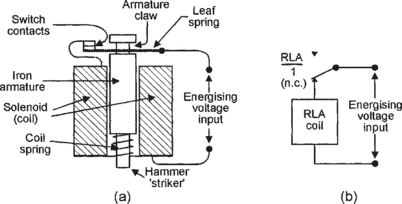
Electric bells and buzzers are widely used sound-generating alarm response units; Figure 1.41 shows their typical basic construction and electrical equivalent circuit. They consist of an iron armature that can move freely within a solenoid that can be energized via a pair of normally-closed switch contacts and a leaf spring. Normally, the armature is forced out of the solenoid by a light coil spring. When a suitable energizing voltage is connected to the circuit the solenoid pulls the armature downwards until its hammer striker hits a sounding board (in a buzzer) or metal dome (in a bell); at this point a claw at the other end of the armature pulls open the switch contact via the leaf spring, and the armature shoots outwards again under the pressure of the coil spring until the switch contacts close again and the process then repeats ad infinitum. Electric bells and buzzers are thus self-interrupting inductive devices; electric bells have their acoustic output energy concentrated into a narrow ‘tone’ band and are thus reasonably efficient, but electric buzzers generate a broad ‘splurge’ of sound and are very inefficient.
Motor-operated units
Electric motors are widely used in industry and commerce to give automatic operation of safety and security doors, and to automatically operate customer-access doors and gates under approved safety/security conditions.
Sound-generator/light-strobe units
All emergency-warning security and safety systems should (ideally) be fitted with an efficient attention-grabbing sound-generator system, to warn all and sundry of the existence of the emergency state, and with some form of light-strobe unit, to visually indicate the precise source of the emergency signals. In buildings, the sound generator may take the form of an electromechanical alarm bell or a piezoelectric or horn-speaker-based electronic siren, and the visual warning may come from a special light-strobe; in automobiles, the sound generator may take the form of a siren or a unit that pulses the vehicles horn, and the visual warning should be obtained by flashing the vehicles lights. In all cases, the alarm-condition indicator unit must be fitted with an automatic timing mechanism that shuts it down after a pre-set period (typically less than 15 minutes) of operation.
In burglar alarm systems, the sound-generator and light-strobe units should be fitted together in a special alarm box and mounted high up on an external wall that (ideally) faces onto a well-used street or passageway. The box should have a built-in back-up battery that is charged via the system’s control panel cables, and the unit should automatically activate the alarm if this cable is cut; the alarm box should be fitted with some form of microswitch that automatically activates the alarm if any attempt is made to open its front cover or pull it from the wall. Units of this type are readily available from electronic alarm system suppliers.