
12
Microactuators
Design and Technology
Abstract
Microactuators are emerging as important tools that are capable of performing the tasks of conventional tools in the macroworld, but they are much smaller and allow greater precision. A review of electrostatic, piezoelectric, and electrothermal microactuators is presented. The basics of these three actuation principles and characteristics are briefly explained to highlight the motivation behind the selection of different microactuators. Various design models of electrostatic, piezoelectric, and electrothermal microactuators are described and compared from the perspective of the mechanism and output performance. Limitations of existing designs are identified to improve some of these microactuators to gain better performance or reliability. Finally, key challenges in different microfabrication techniques associated with their process and compatibility with commercial foundries are highlighted, as this aspect decides the viability of microactuators commercially and economically.
Keywords
Electrostatic; Microelectromechanical systems (MEMS); Piezoelectric and electrothermal microactuators
12.1. Introduction
Since the introduction of the integrated circuit (IC)-compatible surface micromachining process, which enabled miniaturized systems that are composed of mechanical and electrical devices to be fabricated on a piece of silicon (giving birth to the term “microelectromechanical systems” (MEMS) in the mid-1980s), remarkable progress has been witnessed in this new multidisciplinary field. Since the early 1990s, intensive research has been carried out in the MEMS field because they are a fundamental element in many micro- and nanosystems and have a wide range of applications in many different disciplines, such as the optical field, the radio frequency field, and the biological field. Knowing that the ultimate goal of MEMS research is to devise useful microstructures as a complete system, fundamental technological issues, including materials, machining processes, micromechanical devices, and system integration, have to be recognized. The advantages of MEMS lie in their miniaturized size (characteristics length ranging from 1 μm to 1 mm) (Gad-el-Hak, 2002) and low cost, which lends them to potential applications (e.g., in disposable, implantable, in vivo medical equipment). Some technologies have already matured and are well established within commercial markets, such as the micropump in inkjet printing heads (Ernst and Ernst, 2000), accelerometers in automotives for air bag deployment or in consumer electronics (including smart phones and games consoles) for controlling direction in their applications, free-fall sensors in hard disk drives of computers, and gyroscopes in camcorders for blur image compensation (Laermer, 2005).
With MEMS technologies burgeoning at such a rapid pace, it is desirable to understand the main operational feature to further develop and improve the current designs, thus extending their use into further practical applications. Microactuators are regarded as the key element leading to the realization and physical functionalities of MEMS devices. Microactuators can accomplish complex tasks by arranging multiple subsystems in appropriate parallel and series combinations so that they work cooperatively, give higher output, and perform tasks dexterously (Fujita, 1998). Microactuators are defined as actuators (with a scale of microns) produced using standard MEMS-based fabrication techniques including surface and bulk micromachining and other replication techniques (Sahu et al., 2010). These actuators convert (input) energy from one form—such as electrical, mechanical, thermal, magnetic, chemical, and radiation energy—into the mechanical form (output). Common transduction mechanisms are listed in Table 12.1 (Judy, 2005).
Table 12.1
| Input | Output (mechanical) |
|---|---|
| Electrical | Electrostatics Piezoelectricity |
| Magnetic | Magnetostatics Magnetostriction |
| Mechanical | Pneumatics Hydraulics |
| Thermal | Expansion Shape-memory effect |
| Chemical | Phase change Combustion |
Although there are many types of transductions, the basic idea behind making these microstructures work is quite straightforward, to generate force, which leads to simple mechanical work or movement such as bending, tilting, and vibrating. Such force generation can be divided into external forces that are produced in the gap between fixed or stationary and movable parts by means of electrostatic (Tirole et al., 1995) or magnetic energy (Komori and Hirakawa, 2005) and inner forces generated by materials with intrinsic actuation capabilities such as piezoelectric (Gao et al., 2006) and electrothermal materials (Li and Uttamchandani, 2009). Often, different mechanisms can be used to achieve similar results. For example, researchers have reported fine positioning of a read/write head in a hard disk drive using piezoelectric (Zhang et al., 2015; Hu et al., 2016), electrostatic (Mita et al., 2003; Kerdlapee et al., 2014), and electrothermal (Lau et al., 2016; Du et al., 2015) methods and moving optical structures such as a membrane deformable mirror, micromirrors or optical pinholes by means of electromagnetic (Muyu et al., 2015; Kim et al., 2015), electrothermal (Wang et al., 2016; Pengwang et al., 2016), piezoelectric (Pengwang et al., 2016; Rombach et al., 2016), and electrostatic (Pengwang et al., 2016; Csaba et al., 2015) mechanisms.
The focus here is on microactuators that have electrical energy such as voltage or current, or both sources, as their input. This is because the power source is compatible with the power supply of electronic devices, which benefits from the well-developed field of electronic and electrical engineering, thus making the integration of mechanical systems and electronic circuitry on a single piece of chip simpler and more viable. Actuators that usually have an electrical signal as an input include electrothermal, piezoelectric, electrostatic, and magnetic mechanisms.
12.2. Considerations in mechanisms selection
As mentioned earlier, different methods of actuation can be used to perform a task. However, there are several considerations that must be taken into account when making the choice of which actuation principle is to be implemented. The selection of actuation principles is influenced by the enabling technology, structural dimensions, dynamic response, force or torque, displacement, and power consumption, which will be discussed here to reveal the importance of these considerations (Benecke, 1991). Attributes of electrostatic, piezoelectric, electrothermal, and electromagnetic actuators will be discussed in latter sections so that selection criteria for which mechanism to use based on the aforementioned considerations can be determined given that each actuation principle has its own advantages and disadvantages. The choice and the optimization of an approach should be made according to the requirements of a particular application. Also, while the same material constant or physical law applies in the micro- and macroworld, the effect of these parameters on the whole system and its performance changes dramatically when scaling macroactuators down to microactuators. When the scale changes by 1/100, the volume is reduced by a factor of (1/100)3, which is a million times less than before; meanwhile, the gravitational force changes by (1/100)4, making the gravitational pull a trillion times less (Trimmer and Stroud, 2002). With negligible gravitational force, van der Waals electrostatic and capillary forces come into play (Petrina and Petrin, 2007), bringing out new parameters that are not available in the macroscopic world. For example, microspheres with radius of 20–40 μm can be captured by a microcantilever by just a simple contact due to van der Waals force (Haliyo et al., 2003).
12.2.1. Size and physical properties
Small actuator dimensions enable tools to interact with components at a microscale or even nanoscale. However, sensible dimensions are essential for practical reasons. For example, the gap between the arms in a parallel beam is 1–2 μm, to achieve the effective manipulation of 1D nanomaterials (e.g., the alignment of carbon nanotubes on a surface) (Andersen et al., 2009). Besides, designers have to comply with foundries' design rules in their plans (Elbuken et al., 2009; Guan and Zhu, 2010). Reduction in size of a mechanical system generally increases the structural stiffness, even at a thickness of 1 μm (Singh et al., 2006), and its shock resistance (Ernst and Ernst, 2000). Heat transfer mechanics such as transient effects and high-spatial gradient also exhibit significant differences after having been scaled down (Jungen et al., 2006; Ozsun et al., 2009). This is especially crucial in electrothermal microactuators, where slight changes to structure dimensions will alter performance (Li and Uttamchandani, 2009). Besides mechanical properties, there are consequences for electrical properties such as the breakdown voltage, which has a nonlinear relationship with gaps between two electrodes according to Paschen's Law (Lisovsky and Yakovin, 2000).
12.2.2. Output force and displacement range
The type of application affects the range of motion and applied force. Handling objects or specimens that are fragile (e.g., bio- and nanomaterials) requires a very low force, ranging from nanonewtons to micronewtons. For example, forces as low as nanonewtons are required for cell manipulation using microgrippers (Garcés-Schröder et al., 2015). On the other hand, applications such as high-voltage large air gap switches require large deflection and forces up to several hundred microns (Fu et al., 2005).
12.2.3. Actuation resolution and sensing
In the microworld, every single micrometer or nanometer is important. Nanoscale measurements are required to test minute structures such as nanowires and nanotubes (Yong and Tzu-Hsuan, 2015). Electrostatic and piezoelectric microactuators are commonly related to high precision; for example, electrostatic impact microactuators with stepwise motion of 10–20 nm (Mita et al., 2003) and piezoelectric microactuators with displacement of 12.3 nm have been reported (Gao et al., 2006). Recently, electrothermally actuated XY stage can also achieve resolution better than 0.3 nm (Xi et al., 2016). Such ultraprecise positioning is indispensable in applications such as XY stages, optical devices, or the more demanding hard disk drive track positioning (Zhu et al., 2005).
12.2.4. Fabrication and material selection
Fabrication technologies are a crucial determinant of material selection, with silicon still playing the leading role. Ease of fabrication and compatibility to standard ICs would enable microactuators to be mass-produced at a low cost. There is no one material that is perfect for all types of actuation. For example, fast response materials might require high actuation voltage, while slow-response materials need low actuation voltage. In high-speed applications (Huang et al., 2002) or switches (Fu et al., 2005, 2007), if a fast response is desired, materials such as diamond, silicon carbide, alumina, silicon nitride, and silicon are good candidates (Srikar and Spearing, 2003). If a large force is required, titanium carbide, tantalum carbide, or tungsten carbide can be used. However, using non–IC-standard materials will introduce additional costs and fabrication complexity. Hence, a trade-off is inevitable when designing a microactuator. Many techniques such as Ashby approach as Multi Objective Decision Making technique, Technique for Order Preference by Similarity to Ideal Solution, and Vise Kriterijumska Optimizacija kompromisno Resenja methods as Multiple Attribute Decision Making can be used to determine the best material for the intended applications (Yazdani and Payam, 2015).
12.2.5. Power consumption
Power efficiency is a major concern in the macroscopic world, especially for portable devices. There is no difference when it comes to MEMS applications (Moreira et al., 2016). Low power or energy-efficient microactuators that operate at lower working temperatures will reduce nonlinear effects such as plastic deformation (Li and Uttamchandani, 2004) and hence increase the life span.
12.3. Electrostatic systems
Electrostatic forces are most commonly observed in the macroscopic world in daily activities such as combing hair. Such energy has been successfully harnessed in microactuators and it is the most frequently applied actuation because of its versatility (Dai et al., 2007), simplicity, and high compatibility with IC fabrication technology (Zhu et al., 2005; Cheung et al., 1996). No special materials—for example, piezoelectric ceramics or additional elements such as coils—are required, therefore eliminating some of the cost-inefficient assembly process.
12.3.1. Electrostatic actuation
The basic working principle of an electrostatic system involves the concept and structure of the capacitor. It consists of charged, fixed, and movable structures that are electrically isolated and move relative to each other. Energy, W, stored between the plates is given by (Judy, 2005; Haliyo et al., 2003):
where C is the capacitance; g is the gap or distance between plates; a and b are the lateral dimensions of the capacitor; V is the applied voltage; εr,0 are the dielectric constants of elements in the gap.
Derivations of W with respect to g and a yield the electrostatic forces, F:
where Fd acts perpendicular to the capacitor plates and Fa acts in the direction of the capacitor plates. Fd is inversely proportional to the squared distance and therefore is only significant for very small gaps. Fa is independent of the actual position of the structures if the dimensions are large compared with the region of interaction. This result indicates that electrostatic principles are useful in miniaturized devices as the electrostatic force is significant. When the force is constant, the displacement is dependent on potential differences between the plates.
12.3.2. Common features and designs
Electrostatic actuators are often characterized by low power consumption (Kim and Lee, 2006) and a high switching speed (Huang et al., 2002; Krylov and Barnea, 2005). Reduction in volume is easy for electrostatic microactuators because the forces available are only coupled to surfaces. Because of the small critical dimensions within the device—especially that of the gap between stationary and moving parts that is normally in the micron range—problems may arise from applications within real media. This is because of foreign particles such as dust impeding proper operation and thus degrading the performance of the device or even causing failure if the debris creates a short circuit. Actuation voltages reported so far range from 9 to 250 V (Pengwang et al., 2016; Kim and Lee, 2006; Kwon et al., 2005; Lee, 2007; Srinivasan et al., 2010; Sun et al., 2002). Thus, only small deflections can be achieved at a low voltage, which is restrictive in some applications. Electrostatic actuators also suffer from a problem known as “pull-in,” where the movable parts stick to the fixed parts when actuation voltages reach the “pull-in voltage” (Lee, 2007). Because of their small footprint, which ranges from 0.1 to 1 mm2, electrostatic microactuators are used in nanoscale applications (Takahashi et al., 2009), performing tasks within a chip such as fine precision positioning (Mita et al., 2003) or in situ measurement (Dai, 2003). However, in situ use in electron microscopes is discouraged as the electric field may interfere with the scanning electron beam because of the high input voltage. Fabrication of electrostatic microactuators with surface micromachining and using silicon on insulator (SOI) wafers (Kwon et al., 2005) or polysilicon makes them compatible with the electronics interface. The fabrication process is supported by MEMSCAP's standard SOIMUMPs process (Maroufi et al., 2015). Commonly adopted designs such as the comb-drive structure, where two arrays of interdigitated (IDT) fingers—one fixed and the other freely movable—act together to produce an electrostatic force, the parallel-plate structures, and the scratch drive actuator (SDA) will be discussed along with techniques to reduce the actuation voltage and pull-in voltage for these designs. Some recent innovations with unconventional structures will also be presented.
12.3.2.1. Comb-drive actuators
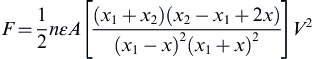
The motion of comb-drive actuators and parallel actuators is controlled by the equilibrium of the electrostatic force and spring force of the suspension system. During lateral motion or parallel actuation, the attractive force between two comb electrodes is mainly due to the fringing fields because the small fingers are thick compared with their width and length (Lau et al., 2010). Because the distance between the comb fingers is constant, capacitance changes linearly regarding the area of the plates that overlap during such movement. Meanwhile, transverse movement of the plates maintains the overlapping area and changes the size of the gap between the comb fingers (see Fig. 12.1) (Sun et al., 2002). Keeping the direction of motion (in both cases) along the x-axis, the electrostatic forces are:
 (12.5)
where n is the number of comb pairs; te is the thickness of the plate; g is the gap spacing; ε is the permittivity of the medium; A is the overlapping area of each finger pair; x1 and x2 are the initial gap spacings; x is the changes in gap spacing; and V is the voltage.
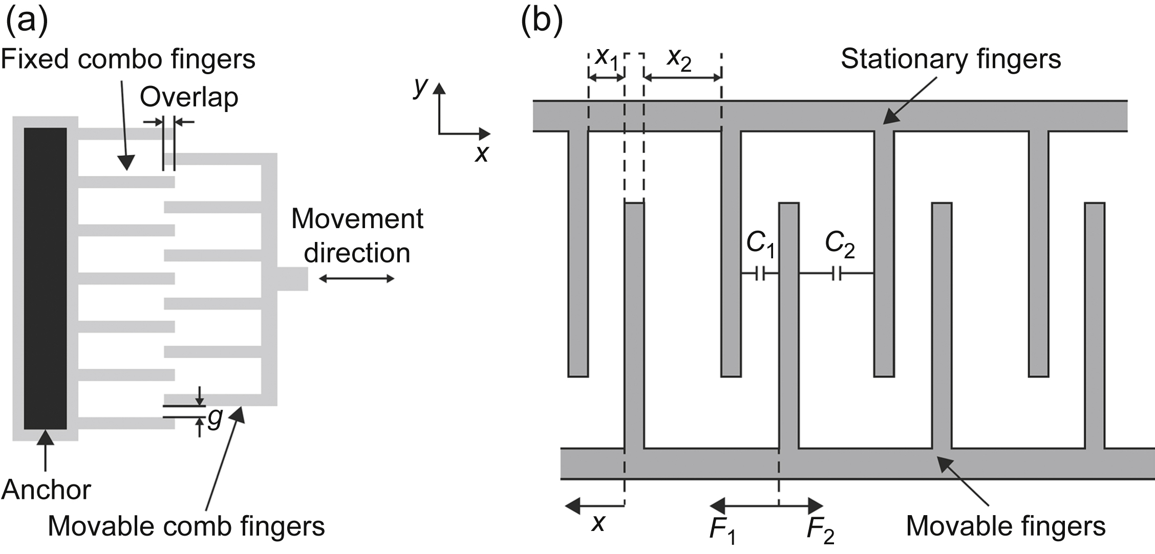
Figure 12.1 Comb actuators: (a) lateral motion with force corresponding to Eq. (12.4) (Lau et al., 2010) and (b) transverse motion with acting force expressed by Eq. (12.5) (Sun et al., 2002).
From both equations, increasing the number of comb pairs and increasing the voltage can increase the force output. Reducing the gap spacing generates a higher force for lateral motion actuation, whereas increasing the overlapping area gives more force to a comb-drive that is in transverse motion. The gap-closing actuator produced a larger force than parallel motion actuators (Sun et al., 2002). Thus, large arrays of comb structures can be seen in many designs (Srinivasan et al., 2010; Sun et al., 2002; Lee et al., 2003) because, as long as the size is within the design constraint limit, they increase the force. For a fixed area, thinner fingers with smaller gap spacing increase the power density because more comb pairs can be packed in. However, comb fingers that are too thin may deform individually and contact each other (Elata and Leus, 2005). The minimum gap spacing between the fingers and the displacement is limited by pull-in or snap through instability (Hirano et al., 1992; Zhou and Dowd, 2003). This limitation is critical in parallel-plate actuators, as transversely driven actuators' displacement is restricted to about one-third of the gap spacing (Piyabongkarn et al., 2005; Seeger and Boser, 1999). Once the driving voltage reaches the critical pull-in point, the microactuators will fail as their mobile comb structures stick to the fixed part (Jaecklin et al., 1992). Moving comb drives also experience vertical levitation due to unbalanced electrostatic fields (Tang et al., 1992).
According to Hirano et al. (1992), a comb-drive actuator operates stably when Ky > Ke, where Ky is the spring stiffness in the y-direction and Ke is the negative spring constant. Generally, under normal conditions the maximum stable displacement  is expressed by:
This is a function of the spring stiffness in the y-direction Ky, the spring stiffness in the x-direction Kx, the length of overlap L0, and the gap spacing g between the fixed and movable electrodes. Different methods for increasing the stable displacement have been reported, including changing the spring constants of the system by altering the maximum setting of the suspension system (Fig. 12.2(a)), reducing the negative spring constant (Fig. 12.2(b)) and shifting the minimum setting of the negative spring constant (Fig. 12.2(c)) (Hou et al., 2006). The mechanical design of the suspension system is therefore crucial for large displacement comb-drive actuators. From Eqs. (12.4)–(12.6), it can be observed that the driving force does not change with motion, so for compliance in the x-direction, linear spring stiffness Kx is desirable, while a high stiffness ratio Ky/Kx is required to avoid pull-in instability and to increase displacement.

Figure 12.2 Increment of displacements: (a) maximum of spring constant shifting; (b) equivalent electrostatic force reduction; (c) minimum of spring constant shifting (Hou et al., 2006); and (d) stable and unstable operating region of a tilted folded beam (Zhou and Dowd, 2003).
Proposed designs include the clamped–clamped beam, which provides a high stiffness ratio Ky/Kx, although stiffness Kx is linear only in the small deflection range. Crab-leg flexure improves the linearity of spring stiffness Kx, but the stiffness ratio reduces at higher displacements (Legtenberg et al., 1996). The folded-beam design is more practical. However, Ky decreases at higher displacements (Dai et al., 2007; Legtenberg et al., 1996). In improved folded-beam designs, there were introductions of tilted folded beams (Zhou and Dowd, 2003), prebent-tilted beams (Grade et al., 2003), and hybrid springs with folded beams (see Fig. 12.3) (Chen and Lee, 2004), which shifts the maximum of spring stiffness Ky and improves the displacement. Besides the parameters relating to thickness and number of comb pairs, linear variation of the comb finger length can enhance the side stability by reducing the overlapping area that affected the side electrostatic force (Grade et al., 2003). Varying the gap spacing also improves the displacement and reduces driving voltage (Hirano et al., 1992). Additional secondary comb structures are capable of extending the displacement by reducing the minimum equivalent electrostatic spring constant, as shown by Hou et al. (2006). (see Fig. 12.4(a)). Chiou et al. (2008) have also demonstrated a 200% increase in displacement by using three cascading comb drives (see Fig. 12.4(b)).
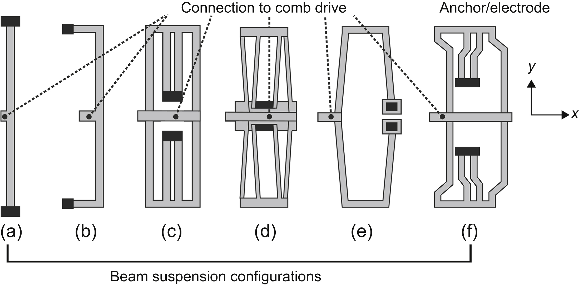
Figure 12.3 Laterally driven comb-drive with different suspension systems: (a) clamped–clamped beam; (b) crab-leg beam; (c) folded beam; (d) tilted folded beam; (e) hybrid spring; and (f) prebent-tilted beam.
To reduce the pull-in effect, Borovic et al. (2006) proposed the use of active feedback to counteract pull-in. To reduce the driving voltage, Yang et al. included a precharged series capacitor with the electrostatic actuator where the new driving voltage required is the voltage difference between the original driving voltage and the voltage across the precharged capacitor (Yang et al., 2014). Displacement in parallel-plate comb actuators can be enhanced by geometry leverage (Hung and Senturia, 1999), the two-beam method (Qiao et al., 2007), employing series capacitors for negative feedback (Chan and Dutton, 2000), current drive (Castañer et al., 2001; Nadal-Guardia et al., 2002; Seeger and Boser, 2003), voltage drive (Rocha et al., 2006), feedback linearization (Jaecklin et al., 1992), and finite time stabilization (He and Geng, 2012) to break the one-third gap limit and use 65%–90% of the available gap. Levitation suppression is attained by alternating the electrodes on every comb finger with a striped ground plane that is positioned underneath the comb structure and designing structures with vertically stiff suspensions. Levitation can be carried out in a controlled manner by using soft suspensions with differential and common mode voltages that are applied to the two electrodes (Tang et al., 1992). However, some designs use this levitation force to move vertically (Lee et al., 2003).

Figure 12.4 Displacement enhancement: (a) sequential engagement of primary and secondary comb drives by voltage switching (Hou et al., 2006) and (b) three-stage cascading comb drives (Chiou et al., 2008).
For applications such as the nanopositioning of micromirrors or in stages that require a higher degree of freedom (DOF), four actuators are usually positioned around a central stage, suspended by a folded beam or a clamped–clamped beam that provides the restoring force. Direct connection of the stage to the comb-drive will limit the displacements and be more susceptible to side instability. Therefore, tethering beams with an appropriately low stiffness, which connect the stage to the comb-drive, allow orthogonal movement and decrease cross-talk between axes (see Fig. 12.5(a)). Lower stiffness, however, leads to end-effector rotation, lower resonant frequency, lower bandwidth, and complex dynamics (Dong et al., 2007). Parallel kinematics mechanisms with comb-drive actuators, as shown in Fig. 12.5(b), provide an increased motion range, high structural stiffness, and a balanced mechanical structure (Dong et al., 2007). Besides producing motions, IDT comb structures can also be used as sensing capacitors (Kim et al., 2008; Liu et al., 2007). However, parasitic capacitance has the potential to overwhelm the signal. A piezoresistive feedback system can be integrated during the nanopositioning stage to resolve this problem (Sun et al., 2008). Rotational movement can also be achieved by incorporating cam rim as shown in Fig 12.5(c) and (d) (Pham et al., 2015).
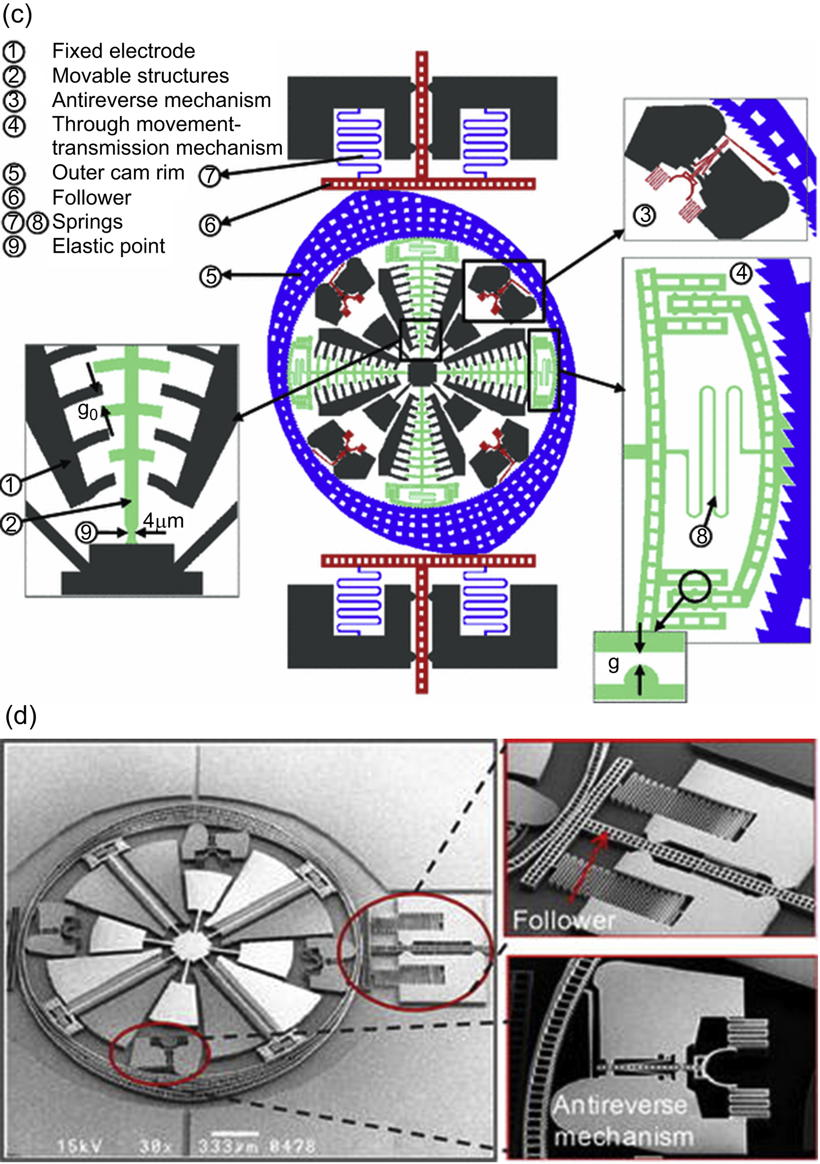
Figure 12.5 Positioning with comb-drive actuators: (a) three-axis nanopositioning stage with z-axis motion induced by parallel-plate actuator (Liu et al., 2007); (b) parallel kinematic 4-bar mechanism with flexure hinge configuration (Dong et al., 2007); (c) a microcam system; and (d) its scanning electron microscope image (Pham et al., 2015).
Nanoelectromechanical systems further push the envelope of microactuator miniaturization, as well as advocating the ease of integrating electrostatic microactuators with IC. Comb drive actuated manipulators can convert the micrometer motion into subnanometer step displacement with high repeatability and force output and with a linear amplification mechanism. A nanomanipulator with dimensions of 1 mm with a 0.15 nm resolution, ±2.55 μm motion range, and 98 μN force capability has been presented by Liu et al. (2007) (see Fig. 12.6). Other designs include combinations of linear and vertical comb-drive actuators with linear and torsional springs (see Fig. 12.7(a)) (Tsai et al., 2008). Kwon et al. (2005) (see Fig. 12.7(b)) demonstrated comb actuators with spadelike fingers that operate in bistability with one input pulse voltage. The comb finger tips are made broader so that when movable combs are between the fixed combs, the smaller gaps between the tips mean that the outward force is stronger. Also, Tee et al. proposed the use of adaptive controls for a 1-DOF electrostatic microactuator system so that it could be driven bidirectionally (Tee et al., 2009).
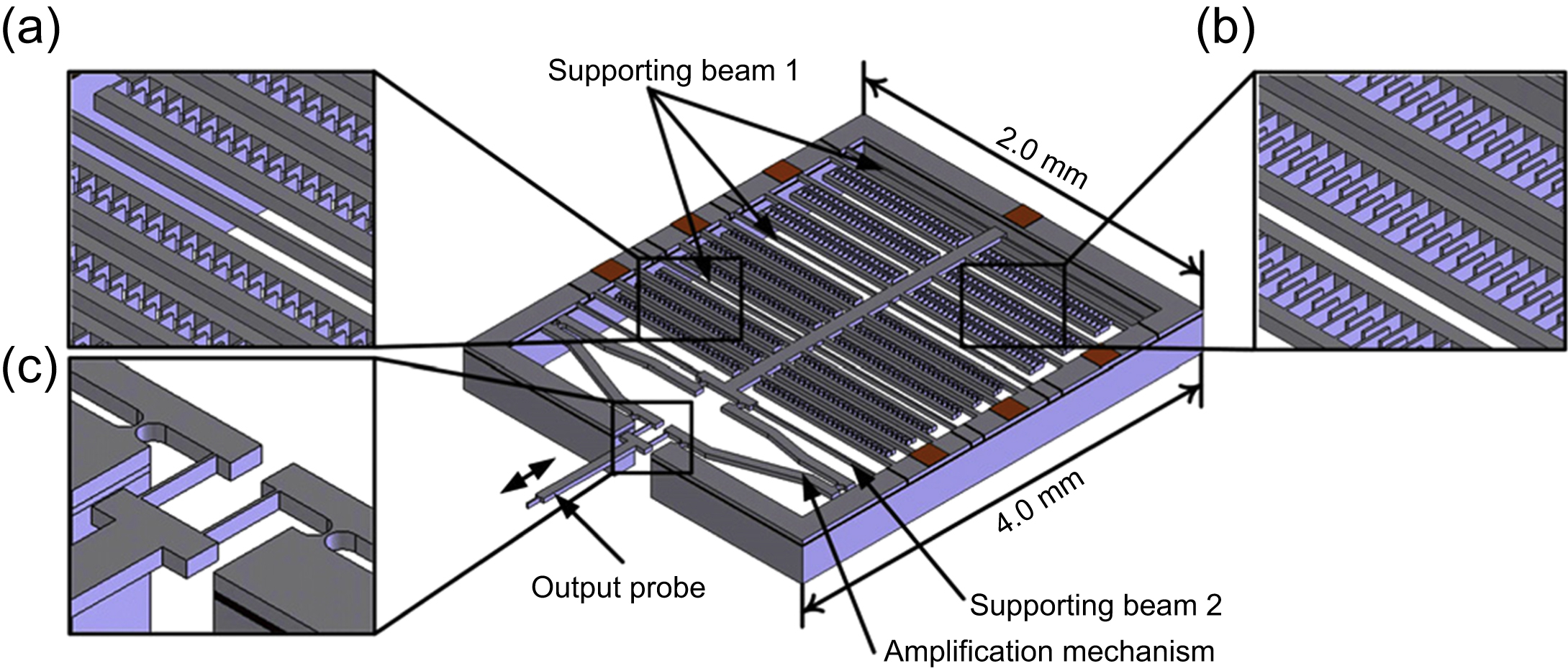
Figure 12.6 Solid model of nanomanipulator with an amplification mechanism driven by comb actuators (Liu et al., 2007). (a) Comb-drive actuator, (b) capacitive displacement sensor, (c) flexure hinges.

Figure 12.7 (a) A two-axis microelectromechanical system scanner with radial vertical comb-drive actuators (Tsai et al., 2008) and (b) an electrostatic microactuator with spadelike comb structures for bistable latching (Kwon et al., 2005).
12.3.2.2. Parallel-plate actuator
This configuration works in a similar way to the transverse mode comb actuators, except that it has only one pair of plates instead of a large array. It also suffers from pull-in instability and displacement of one-third of the gap spacing. The solutions to these problems are the same as the solutions to problems in parallel-plate comb actuators. Parallel-plate actuators are often employed to move a micromirror or three-axis stage vertically while horizontal movements are actuated by comb drives (Srinivasan et al., 2010; Liu et al., 2007). Curved electrode actuators have been proposed for use in situations where the gap is small near the anchored edge of the electrode and gradually increases along the electrode to obtain larger displacement than conventional parallel-plate actuators (Legtenberg et al., 1996; Shao et al., 2010). An insulator layer (Legtenberg et al., 1996) or bumper (stopper) (Shao et al., 2010) is formed along the curved electrodes (see Fig. 12.8(a) and (b)). To overcome limitation on gap spacing because of the commercial Poly Multi-User-MEMS-Process (PolyMUMPs), an L-shaped spring for electrostatic actuated deformable micromirrors (see Fig. 12.8(c)) (Hu et al., 2010), which increases the deflection, has been proposed. Also, slit and grating actuators, which have an opening on the movable plate and fixed electrodes gratings below the slits, reduce pull-in stability, can extend travel range, and lower actuation voltage (see Fig. 12.8(d)) (Lee, 2007).
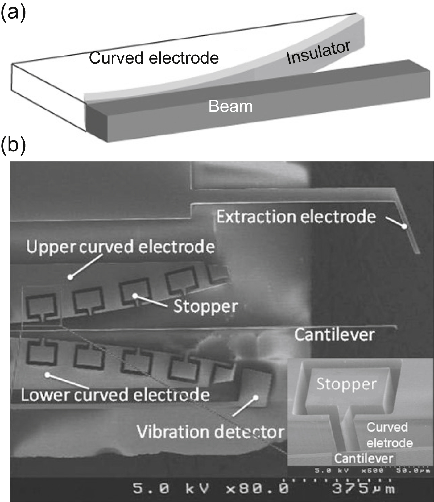
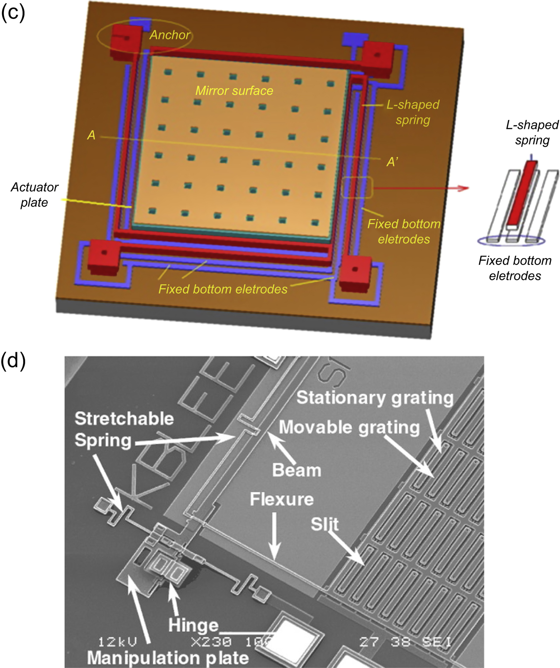
Figure 12.8 (a) Curved electrode with an insulator layer (Legtenberg et al., 1996); (b) curved electrode with stopper (Shao et al., 2010); (c) an L-shaped spring suspended micromirror (Hu et al., 2010); and (d) slit actuator (Lee, 2007).
12.3.2.3. Scratch drive actuator
SDAs (Honarmandi et al., 2010; Li et al., 2002) comprise an L-shaped plate and bushing and support arms that are connected to a spring box. By applying a bipolar pulse voltage, the plate is attracted toward the substrate during the positive cycle. However, the end of the plate, which is attached to the bushing, cannot be pulled down and is therefore tilted, sliding forward because of the warping of the plate. When the voltage goes to the negative cycle, strain energy in the plate will pull the actuator forward as a one-increment step. This type of actuator is capable of generating high forces (>200 μN), large displacement (∼100 μm), and nanometer positioning resolutions (∼10 nm). Its speed can range from 70 to 250 μm/s, depending on the amplitude and frequency of the input signal. However, minimum driving voltages of 60 V may be required and can go as high as 290 V (Li et al., 2002). Also, the upward–downward and impact motion that is caused by warping may not be suitable for gripping and precision nanoassembly operations. SDAs are highly sensitive to plate length and applied voltage. A larger step size can be obtained by increasing the bushing height or the applied voltage. Driving voltages change linearly with the bushing height and exhibit an inverse relationship with the plate length (see Fig. 12.9) (Honarmandi et al., 2010).
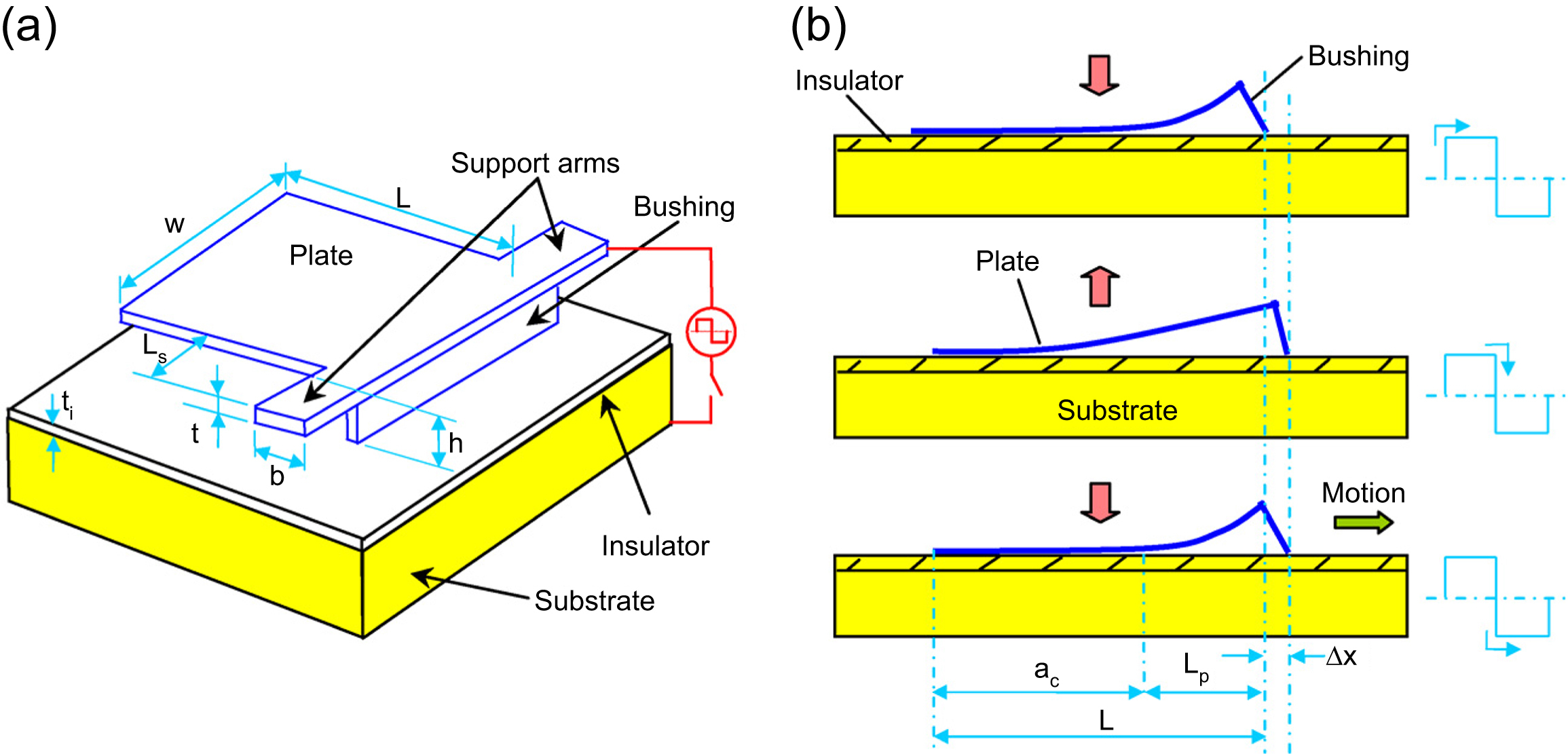
Figure 12.9 (a) 3D configuration of a scratch drive actuator (SDA) and (b) illustration showing warping motion of SDA (Honarmandi et al., 2010).
12.3.2.4. Other designs
Recent innovations with new microactuator designs to either improve the actuator's displacement, output force, or lower the driving voltage include the fishbone-shaped comb-drive microactuator and two-end fixed beam driven by both vertical and horizontal forces. The slant comb fingers of a fishbone-shaped microactuator can produce stronger electrostatic fringing forces than ordinary straight comb fingers because the sharp edges of the fishbone-shaped comb-drive has highly concentrated electric field as shown in Fig. 12.10(a) (Megat Hasnan et al., 2014).
In the two-end fixed beam design as shown in Fig. 12.10(b) (Tian et al., 2016), the beam is compressed using electrodes at both ends. Then, the deflection of the deformed beam at its center part because of compression from both ends is further increased by driving another set of electrode at the center of the beam to achieve large displacement.
Segmented meanders zipper actuators are also proposed to achieve large displacement. Selected regions of oxide layer are removed from the actuator beam, resulting in curvature in certain regions because of residual stress gradient induced by the thermal oxide film that gives static large displacement to the actuator (Felder et al., 2015).
A sawtooth-like microactuator with both the bottom and top electrodes on the same side of the surface but separated by air gap and spacers has also been proposed to achieve large deflection. When voltage is applied, the electrostatic force between the electrodes causes the top electrode to bend. The spacers constraint further bending of the top electrode but at the same time transfer the surface strain to the whole microactuator, which lead to larger deflection of the cantilever (Conrad et al., 2015).
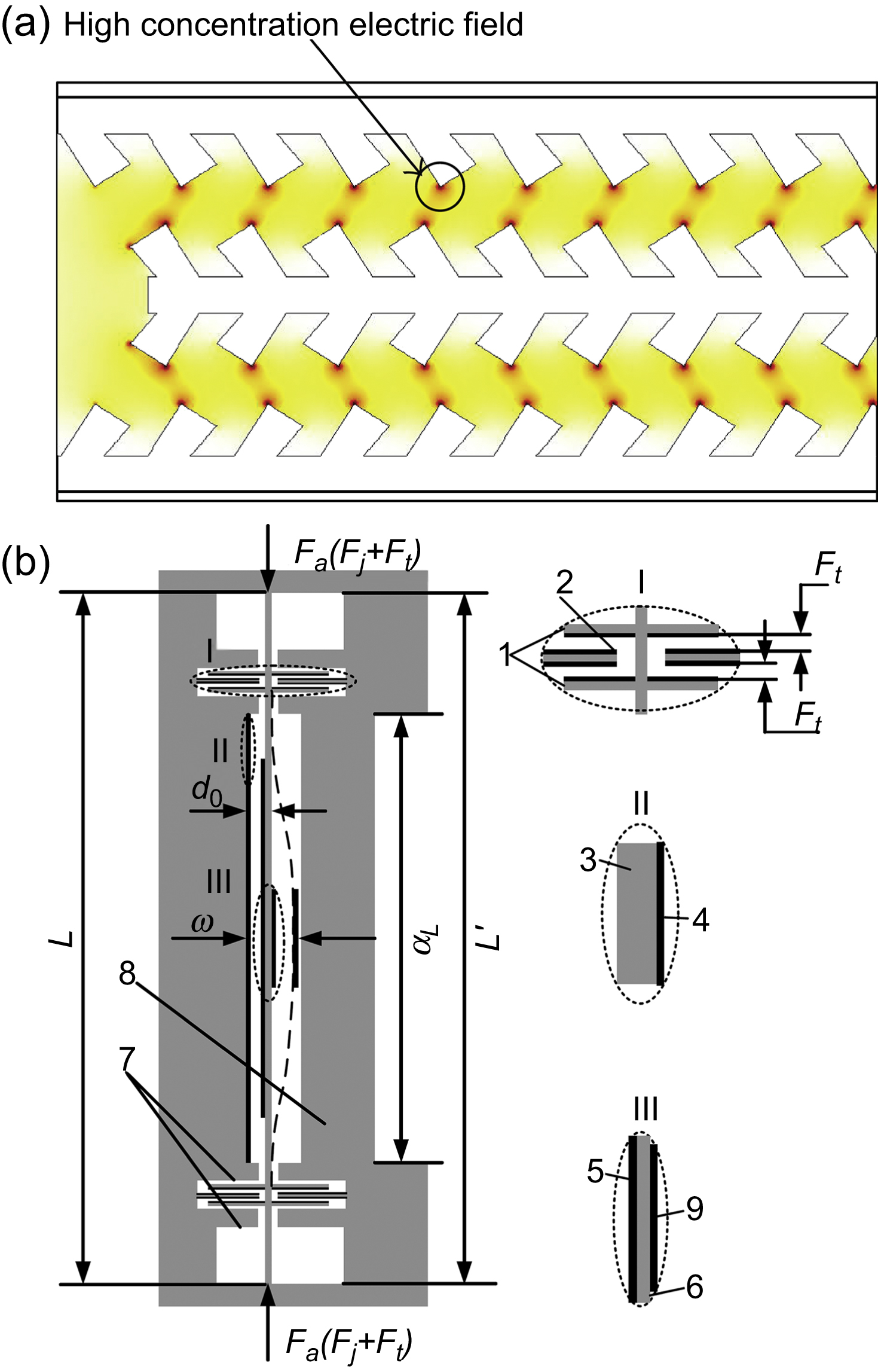
Figure 12.10 (a) Electric field distribution of single finger fishbone-shaped electrostatic comb-drive actuator (Megat Hasnan et al., 2014); (b) Schematic of microbeam. 1, Movable regulation electrode. 2, Fixed adjusting electrode. 3, Fixed substrate. 4, Fixed plate of driving electrode. 5, Movable plate of driving electrode. 6, Microbeam. 7, Guide groove. 8, Outside frame. 9, Test electrode (Tian et al., 2016).
12.4. Electrothermal systems
Failures observed in ICs such as buckling and expansion as a result of the different thermal expansion coefficients (Royce, 1988) of silicon and metal have shown the capability of miniaturized systems to generate large forces. Mechanism of electrothermal microactuators is realized by utilizing such an effect with proper design and thermal management. Therefore, electrothermal actuation is preferable to piezoelectric and electrostatic mechanisms when large forces and deflections are required.
12.4.1. Electrothermal actuation
Electrothermal actuators operate on the principle of Joule heating and differential thermal expansion (Bechtold et al., 2005). An electrical current flows through the actuator, which is usually an electrical closed loop, and heat is generated. The heat generated in an ohmic conductor is expressed by:
where j is the current density vector; ρ is the specific electric resistivity; I is the current passing through the materials; R is the materials' resistance; and Q is the generated heat (power) per unit volume. A general thermal expansion is given by Barron (1998):
where l is the final length; l0 is the initial length; α is the thermal expansion coefficient; and ΔT is the temperature change.
From Eq. (12.8), it can be seen that Joule heating in electrothermal actuators is heavily dependent on the properties of materials (e.g., the physical properties, the electrical properties, the thermal properties, and the volume try of the actuators). This indicates that careful selection of materials and geometry is crucial for the optimal performance of electrothermal microactuators. Joule heating causes temperature changes within the actuators, and the temperature variation leads to differential thermal expansion.
12.4.2. Common features and designs
Electrothermal microactuators have a fairly slow response time compared with piezoelectric and electrostatic microactuators; the transducers require time to heat up and cool down, thus limiting their operating frequency to less than 1 kHz. For example, Li and Uttamchandani (2009) reported that the device reacts 17.3 ms after the voltage is applied, which is about 1000 times slower than piezoelectric actuators. Operation at frequencies beyond the response time will confine the actuator to one position (Cao et al., 2007). Electrothermal actuators also use large amounts of power, with the power requirements ranging from several milliwatts (Li and Uttamchandani, 2009; Cao et al., 2007; Kolesar et al., 2000; Wu and Xie, 2008; Zhang et al., 2006) to watts (Syms et al., 2006), at several volts and several milliamps of current (see Fig. 12.11). However, electrothermal actuators are capable of exerting high output forces of up to a few millinewtons (Aioubi et al., 2004; Shivhare et al., 2016) and producing large displacements at a fairly low excitation voltage (<10 V); for example, with only 7 V, displacement of 28 mm (Zeng et al., 2015) can be achieved. Many papers have reported the use of the services of PolyMUMPs to fabricate their devices (Cao et al., 2007; Kolesar et al., 2000; Chen et al., 2002), indicating that fabrication of electrothermal microactuators is well supported by the industry and can be easily commercialized because PolyMUMPs is a commercial foundry and the industry's longest-running MEMS multiproject wafer service, working with systems that are compatible with current IC manufacturing processes (Judy et al., 1990). Design configurations presented so far have included U-shaped (see Fig. 12.12) (Li et al., 2007), multimorph (more commonly known as “bimorph”) (Wu and Xie, 2008), and V-shaped (chevron) (Shay et al., 2008).

Figure 12.11 Response time and current requirement of an electrothermal microactuator (Wu and Xie, 2008).
12.4.2.1. U-shaped (pseudo-bimorph) beam
Also dubbed “the Guckel” (Guckel et al., 1992), this electrothermal actuator configuration is an electrically closed loop that resembles a “U” shape. It generally consists of a “hot” arm and a “cold” arm that usually has a flexure in the in-plane U-beam as shown in Fig. 12.12(a). The hot arm has a higher temperature than the cold arm because it has a narrower conductive path, which increases the resistivity and current density. In-plane deflection toward the cold arm is achieved by the differential thermal expansion of the arms, giving it one operation mode (“open” or “closed”). The flexure is a thin structure positioned between the cold arm and the anchor that amplifies the deflection. When a current is passed through the narrow and wide arms in parallel, as shown in Fig. 12.12(b), the structure will deflect toward the narrower arm because the wider arm has a lower resistance, hence drawing more current and becoming hotter than the narrow arm. Another configuration is the long–short beam, which bends toward the shorter arm because the longer beam elongates more than the short beam when heated as shown in Fig. 12.12(c). By adding an extra buckling arm, which exploits the buckling effect as shown in Fig. 12.12(d), higher actuation can be achieved.
Out-of-plane unidirectional U-beams, as shown in Fig. 12.12(e), are machined so that the initial stress of the material (e.g., silicon) causes the long, suspended cantilever to slightly bend upward from the substrate (Li et al., 2007). Subsequent heating causes expansion of the outer hot beam while being constrained by the center cold beam, leading to further vertical movement. Unidirectional U-beams can also be made to have the hot arm positioned above the wider cold arm, which works on the same principle as in-plane U-beams as shown in Fig. 12.13(a) (Yan et al., 2004). Other designs have been reported to give operational directions. A bidirectional vertical actuator, shown in Fig. 12.13(b) (Yan et al., 2004), is composed of two U-shaped arms (top and bottom) that are connected at the free edge. Passing a current through the bottom U-arm bends the tip upward, while applying voltage across the anchors of the top U-beam deflects the actuator downward to the bottom arm. A 2-DOF design that is able to deflect horizontally and vertically has been reported (see Fig. 12.13(c)) (Elbuken et al., 2009). It has four equidistant parallel arms that are anchored to the substrate at one end and connected to each other by a rigid central shuttle at the tip of the beam. The outer and inner arms are at different elevations, with the outer arms slightly higher. If a closed loop is formed appropriately with two of the arms, the deflection directions of the microactuator can be manipulated. For example, passing a current through the two beams on the right produces motion to the left, while exciting the outer arms gives rise to negative vertical motion.

Figure 12.12 In-plane unidirectional U-shaped beams: (a) in series; (b) in parallel (Moulton and Ananthasuresh, 2001); (c) long–short arms (Pan and Hsu, 1997); (d) out-of-plane unidirectional U-beam (Li et al., 2007); and (e) with buckling arm (So and Pisano, 2015).
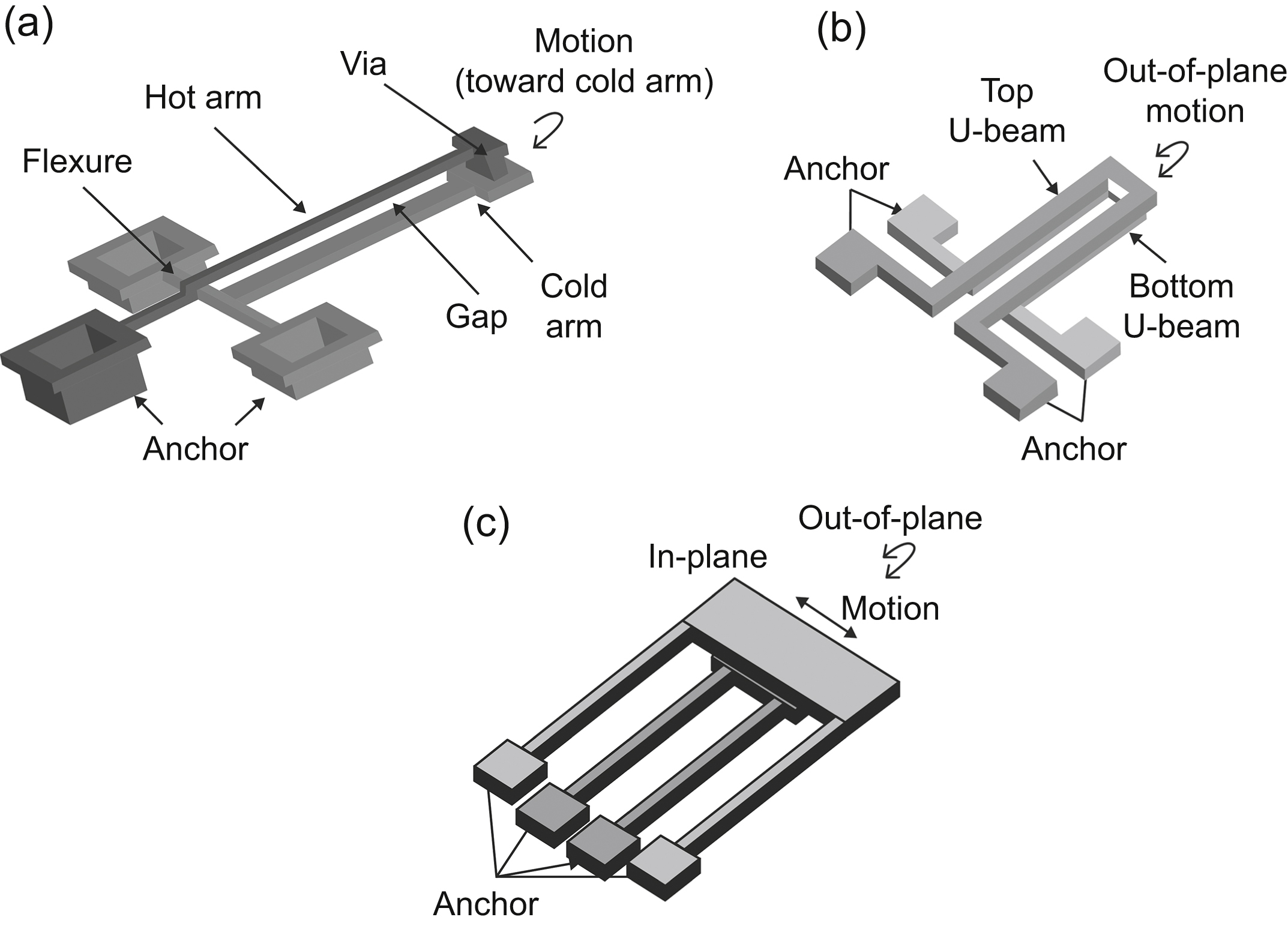
Figure 12.13 Out-of-plane U-beams: (a) unidirectional; (b) bidirectional (Yan et al., 2004); and (c) with 2-DOF.
As mentioned earlier, geometry is an influential factor in actuators' performance. The ratio of the cold arm length, Lc, to the hot arm length, L, should be around 0.85–0.9, which also means that a flexure of 10%–15% of the total arm length and the wider cold arm are required for maximum deflection (Chen et al., 2002; Karbasi et al., 2010). Using thicker arms for in-plane operating actuators increases the out-of-plane stiffness, thus avoiding some of the unwanted torsion of arms, the frequency-dependent cross-coupling effects and misalignment in operations such as gripping nanoscale objects (Mølhave and Hansen, 2005). However, the width and the thickness must not be too great or the beam will be too stiff and cold to produce high deflection. Also, the beams must not be too long or there will be increased electrical resistance, and therefore more power will be consumed and less force will be produced because of bowing. Failure because of the stiction of the beams to the substrate during fabrication may also occur (Huang and Lee, 1999). Peak temperature is found at the middle of the hot beam, which could lead to failure due to the high temperature (Zhu et al., 2006). It can be lowered by widening the central region of the beam (Fig. 12.14(a)), thus improving the power-handling capability (Li and Uttamchandani, 2004) and preventing failure due to localized melting or permanent plastic deformation. Although this modified structure leads to lower deflection than those with uniform arms at the same input power, it can operate at a higher power and produce higher maximum displacement than conventional structures. Large temperature differences between the hot and cold arms lead to a higher deflection (Ginet et al., 2007). Therefore, long–short beams with uniform arms perform poorly (Karbasi et al., 2010). This can be rectified by adding another hot arm with a separated anchor in parallel with the existing hot arm and cold arm (Fig. 12.14(b)). Current only flows through the hot arms; the cold arm and flexure no longer conduct the current, resulting in a lower temperature and allowing the flexure to be narrower and thus more flexible. Consequently, a larger temperature difference and a higher deflection are attained. A pair of U-beams with multiple hot beams can perform different actuation modes exciting different beams (Fig. 12.14(c)) (Andersen et al., 2009).
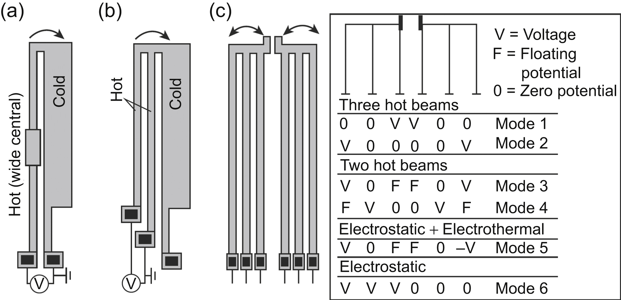
Figure 12.14 Top view of modified U-beams: (a) U-beam with widened hot arm at middle region of hot arm; (b) double “hot” arm U-beam; and (c) a pair of U-beams with uniform arms that enable six different actuation modes.
Also, deflection can be enhanced by depositing a highly conductive metal thin film, such as gold or aluminum, onto the cold arm (Chen et al., 2002; Karbasi et al., 2010; Henneken et al., 2008). This reduces the thermal resistance and the temperature on the cold arm to give a larger temperature difference, thus doubling the deflection. However, these thin films are damaged at very high temperatures (Henneken et al., 2008). Incorporation of diamond nanoparticles into nickel actuators has been shown to reduce power consumption by 73% and has improved performances by enhancing their properties (Tsai et al., 2006). Actuators built on trenched substrates can reduce power consumption because heat loss from the substrate is minimized (Cao et al., 2007).
12.4.2.2. V-beam (chevron/bent-beam) actuator
The V-beam design features an array of bars that are attached symmetrically to either side of a movable central shuttle. The beams are designed with a prebend angle, α, that predefines the buckling direction. Joule heating causes the beams to expand and pushes the shuttle in the direction of the opposite side to angle, α (Fig. 12.15(a)). Within thermal buckling limits, longer beams can extend the travel range of the shuttle. More beam pairs produce more out-force. Chevron actuators also provide flexibility by controlling the peak temperature and gripping force by increasing the beam's cross-sectional area. Similar to U-beam, displacement of the V-beam actuator can be improved by varying the cross-sectional area by contouring the hot arms along the actuator's length, which provides more uniform temperature distribution along the length. Peak temperature and power consumption are therefore reduced. Also, contouring reduces thermal errors, thereby increasing the accuracy of the actuator that is required for nanopositioning applications (Li and Uttamchandani, 2004; Chen and Culpepper, 2006). Because of the processes that take place during fabrication, a parasitic angle, θ, is usually formed between the beams and the horizontal plane, as shown in Fig. 12.15(b). Vertical motion of chevron actuators can be enhanced by increasing this angle (Varona et al., 2009). Fig. 12.15(c) shows another bent-beam actuator with only one beam connecting the anchors at both ends and without a shuttle (Zhang et al., 2006). It could be challenging to fabricate small features with smooth sidewall surfaces of the slanted beams of V-shaped actuators. An alternative is to use the Z-shaped beam as shown in Fig. 12.15(d) (Guan and Zhu, 2010).

Figure 12.15 Schematic images of actuation: (a) Chevron-type horizontal actuator; (b) modified chevron for vertical actuation (Varona et al., 2009); (c) cascaded bent-beam actuator (Zhang et al., 2006); and (d) an electrothermal microactuator with Z-shaped beam (Guan and Zhu, 2010).
12.4.2.3. Bimorph actuator
In electrothermal bimorph actuators, mechanical motion is achieved by the differential expansion of two or more different materials, with a large variation in the coefficient of thermal expansion. Materials with a higher thermal expansion coefficient, such as platinum or gold, usually comprise the top layer (Aioubi et al., 2004). Bimorphs are initially curled up because of the intrinsic stress that is generated in the structural layers during fabrication, but they flatten when voltage is applied (Wu and Xie, 2008; Aioubi et al., 2004). Bimorph thermal actuators are advantageous because of their simplicity in fabrication, large array integration, large actuation range, and low voltage operation, which makes them suitable for parallel processing and large throughput applications. However, such multilayer structures will suffer from delamination and the top layer will be damaged at elevated temperatures (Chen et al., 2003), although bimorphs of titanium tungsten (Ti–W) and silicon nitride (SiN) have been shown to be capable of sustaining large deflection without delamination (Fig. 12.16) (Boutchich et al., 2008). Many materials can be exploited as electrothermal bimorph. For example, vanadium dioxide has been reported to be suitable if high-speed actuation is required where the actuator reaches its steady state in around 8.3 ms and the performance can be further enhanced to just 3.3 ms by applying an extra layer of single-wall carbon nanotube (Wang et al., 2015). Shape-memory alloy materials have been recently used as electrothermal microactuators because of their attractive features such as high work density, large actuation force, resistance to corrosion, and compatible with standard MEMS process (AbuZaiter et al., 2016; Kabla et al., 2016). A bimorph made of super-aligned carbon nanotube sheets (SACNS) and polydimethylsiloxane (PDMS) composites was demonstrated to be able to reach 9.5 mm at 98°C (with a displacement coefficient of 44 μm/[100 μm × °C]). This bimorph is highly reliable and has a long working life because no delamination was found in it. However, the power consumption can be quite high (Chen et al., 2011). Displacement amplification can be carried out by cascading bimorphs (Wu and Xie, 2008; Geisberger and Sarkar, 2006), which is similar to the segmented meander zipper actuator. Also, rotary and linear actuators have been designed based on this principle (see Fig. 12.17) (Geisberger and Sarkar, 2006).
12.4.2.4. Electrothermal actuators based on unconventional materials
Possessed of unique characteristics (Lau et al., 2008; Nguyen et al., 2004), the SU-8 polymer is attractive as an electrothermal actuator that offers low handling forces, large displacement, and low operating voltages. Therefore, the SU-8 polymer is suitable for the handling and manipulation of micro- or nanoscale and biological applications (Nguyen et al., 2004; Duc et al., 2008). However, their low heat conductivity leads to a slower thermal response (Lau et al., 2008; Duc et al., 2008). Lau et al. presented a concept of embedding silicon structures topped with aluminum track within the SU-8 epoxy with a 30% silicon to 70% SU-8 ratio. This improves the properties of the actuator, such as Young's modulus, thermal stress, and work density (by more than 2.5 times), thermal expansion (by 5% more), and response time (by 20%) (Lau et al., 2010). The aluminum film track is used to enable Joule heating by allowing a current to pass through it and subsequently heat up the silicon skeleton underneath. Another configuration fills the gap between the silicon comb fingers with the polymer. Confinement of the polymer inside the high-aspect ratio silicon structure leads to higher displacement, higher stiffness, and less out-of-plane motion (Duc et al., 2008). Lau et al. have also employed this design in rotary micropositioner in hard disk drives recently (Lau et al., 2016).
Another special material that is used in electrothermal actuator is hydrogel. Hydrogels are capable of expanding up to four times their original volume (Deng et al., 2015). The hydrogel is contained in a structure adjacent to a Peltier element. The hydrogel will expand or shrink its volume when it is heated up or cooled down by the Peltier element. The expansion or contraction of the hydrogel can be directly used to do the work or drive other structures.
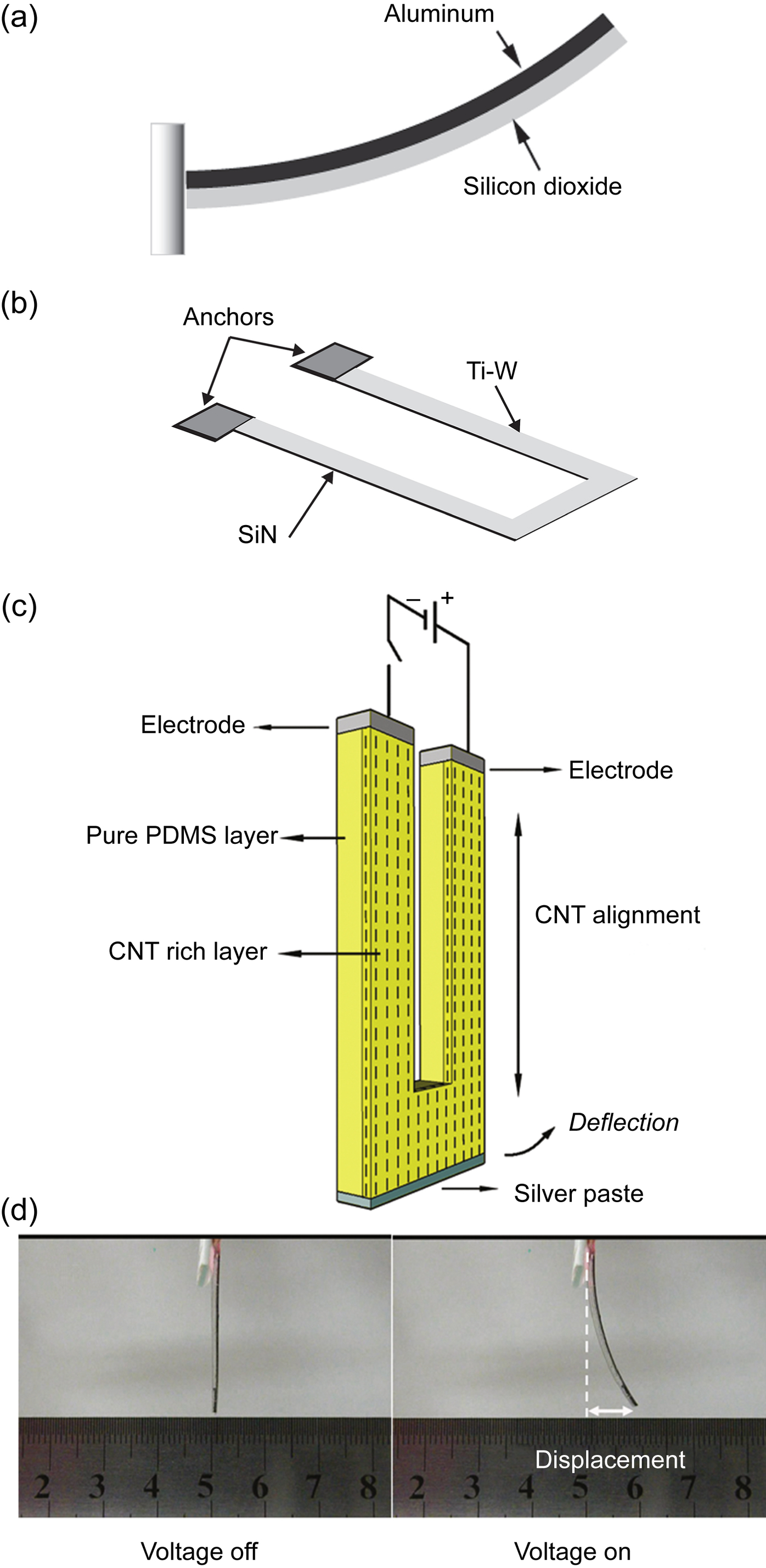
Figure 12.16 (a) A conventional bimorph cantilever; (b) a U-shaped titanium tungsten (Ti–W)/silicon nitride (SiN) bimorph; (c) schematic structure of the SACNS/PDMS composite actuator. The dashed lines represent the direction of CNT alignment. (d) Photographs of an actuator without (left) and with (right) an applied DC voltage of 40 V. CNT, carbon nanotube; PDMS, polydimethylsiloxane; SACNS, super-aligned carbon nanotube sheets. Reprinted with permission from Chen, L., et al., 2011. High-performance, low-voltage, and easy-operable bending actuator based on aligned carbon nanotube/polymer composites. American Chemical Society Nano 5 (3), 1588–1593, Copyright (2011) American Chemical Society.

Figure 12.17 Scanning electron microscope images of: (a) initial fabricated position of cascaded bimorph scanning mirror; (b) plan view; and (c) side view of final position with increased residual stress with scale bar representing 100 μm (Geisberger and Sarkar, 2006).
12.4.2.5. Compliant mechanism
Combinations of the aforementioned actuators in an appropriate configuration lead to the design of electrothermal compliant mechanisms (ETCs). In ETCs, elastic deformation due to thermal expansion provides the actuation force to the revolute joints hinges and flexures and amplifies the motion. There have been demonstrations of various ETC mechanisms that use a combination of U-beam actuators to achieve lateral translation and expansion (Moulton and Ananthasuresh, 2001) (see Fig. 12.18(a)). Parallel configuration is used in 3-DOF planar micromanipulators. Tsai et al. (2005) proposed 28 different feasible configurations to transform the conventional rigid links kinematic macromechanism into ETC mechanisms. Combination of U-beam and V-beam has also been proposed by Margarita et al. (2016). Compliant designs have been developed by topology optimization (Huang and Lan, 2006; Sardan et al., 2008), which use a finite element-based method with a multiparameter optimization algorithm for the optimal material distribution within a fixed domain. Compared with a pair of three-beam designs (Andersen et al., 2009) (Fig. 12.14(c)) without topology optimization, a topology-optimized electrothermal actuator (see Fig. 12.18(b)) (Sardan et al., 2008) is able to provide a higher gripping force and lower end-effector temperature within the same geometric domain as the double–U-beam microactuator. The end-effector was measured to be at 229°C and deflection was up to 1 μm with a gripping force of 18–20 μN.
12.5. Piezoelectric systems
Piezoelectric materials such as lead zirconate titanate (PZT) and polyvinylidene fluoride (PVDF) are usually employed as the transducers.
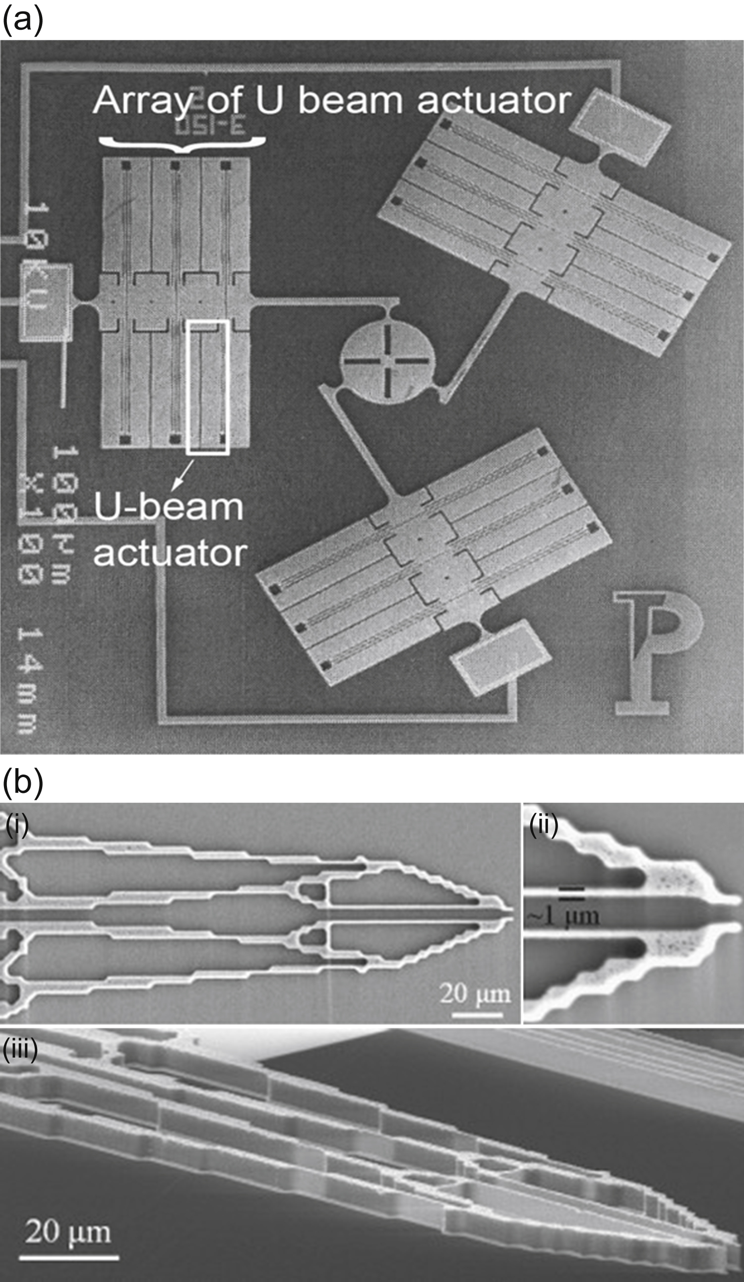
Figure 12.18 Scanning electron microscope images: (a) 3-DOF planar micromanipulator with array of U-beam actuators in parallel configuration (Moulton and Ananthasuresh, 2001) and (b) topology-optimized electrothermal actuator microgripper from different views (Sardan et al., 2008).
12.5.1. Piezoelectric actuation
Piezoelectric materials are physically deformed when an electric field is applied to them. Conversely, these materials produce electrical energy when subjected to mechanical strain. These relationships can be described by:
where S is the mechanical strain; T is the mechanical stress; s is the compliance; d is the piezoelectric strain coefficient; E is the electric field; D is the electric charge density displacement; ε is the dielectric constant of piezoelectric material; I, J are 1, 2, 3, 4, 5, 6; and i, j are 1, 2, 3 denoting the x, y, z directions.

Note that without the piezoelectric strain coefficient (d), Eqs. (12.9) and (12.10) are merely Hooke's law and Gauss' law, respectively. Thus, the performance is dependent on the materials; the piezoelectric strain constant acts as a medium for the transduction mechanism to work. S, T, D, and E are vectors. The presence of an electrical field across the material has an implication on its physical properties, while the mechanical stress has an effect on the permittivity of the material. For example, microactuators are excited by an electric field, usually a voltage source, and can cause the piezoelectric material to deform according to the direction of the applied voltage, thus inducing mechanical forces.
Common excitation modes are the 33 mode and 31 mode, as shown in Fig. 12.19. In the 33 mode, both the voltage and the force act in the 3 direction, while the 31 mode operates with the voltage acting in the 3 direction and the force being exerted in the 1 direction. The direction of the voltage can be manipulated by poling the material. If a voltage, V, is applied to a stress-free piezoelectric material in the 3 direction, T = 0 and E = Δl = δv[0 0 E3], Eq. (12.9) can be simplified as:
The displacement ΔX in the 1 direction can be expressed as:
where X is the piezoelectric ceramic length in the x-direction. E3 = V/X, hence
where variation of length in the y and z direction can be obtained in a similar fashion.
12.5.2. Common features and designs
Like their electrostatic counterpart, piezoelectric microactuators are often deployed in high-speed applications because of their rapid response time (see Fig. 12.20) (Ivan et al., 2009) and low-power requirement (Oldham et al., 2008). Large forces (i.e., hundreds of micronewtons) are demonstrated even in simple designs such as a thin film (Oldham et al., 2008) or a beam (Kommepalli et al., 2009) with an excitation voltage of 20 V. Although conventional piezoelectric microactuators produce displacement of only 35 nm to 1.5 μm (Morita et al., 2002; Tsuchiya and Davies, 1998; Wang et al., 2002) with a high actuation voltage (from 50 V to several hundred volts) and have a large lateral dimension (Wiederkehr et al., 2008) or footprint (usually measured in mm2), a considerable number of improvements have been reported. Those findings showed that piezoelectric microactuators are quite versatile: small-step piezoelectric microactuators can be employed in fine-positioning applications, whereas large displacement microactuators can be integrated into devices such as micromirrors.
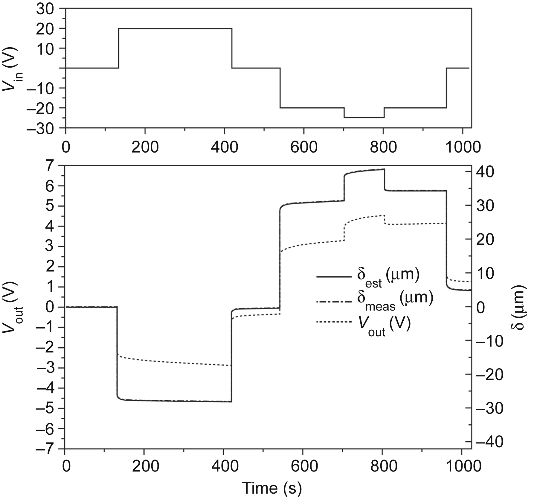
Figure 12.20 Response of piezoelectric microactuator where the upper image shows the applied voltage and the lower image shows the output (displacement and voltage). The microactuator reacts almost instantly (Ivan et al., 2009).
Fabrication of piezoelectric ceramics is usually carried out at temperatures between 350 and 700°C (Oldham et al., 2008; Kommepalli et al., 2009), with some going over 1000°C (Jing and Luo, 2005; Zurn et al., 2001) for several hours. Such temperatures are too high (Chang et al., 2007) for the integration of piezoelectric microactuators with post–complementary metal–oxide–semiconductor (CMOS) fabrication because the component will be damaged at the elevated temperature. Prefabrication of PZT is difficult as it poses a contamination risk to the tools, which are also used in CMOS fabrication processes (Tamagawa et al., 1990; Trolier-McKinstry and Muralt, 2004), and silicon substrates can be contaminated as a result of lead diffusion (Ferrari et al., 2009). Carrying out separate fabrication processes is inefficient in terms of time and cost. New materials, such as aluminum nitride (AlN) (Giordano et al., 2009), have been found to be compatible with conventional CMOS fabrication process. Other non–lead-based materials include zinc oxide (ZnO), barium titanate BaTiO3 (BT), bismuth sodium titanate (BNT), Ba(Ti0.95Zr0.05)O3 (BTZ), bismuth ferrite BiFeO3 (BFO), sodium bismuth titanate (NBT), PVDF, and electro-active paper (EAPap) (Asif et al., 2016). Piezoelectric materials are usually deposited on the surfaces of slender structures such as cantilevers, on large surfaces as a membrane-type actuator, or are used as a bulk material as actuator.
12.5.2.1. Cantilever-type piezoelectric actuators
A piezoelectric cantilever is usually composed of at least one layer of piezoelectric film and one layer of a passive substrate such as a nickel alloy, titanium, or silicon, which operates in an out-of-plane motion. An unimorph structure consists of only one layer of piezoelectric film, usually on the top, whereas bimorph structures are made of two layers of piezoelectric materials that sandwich the center shim. Sometimes, the piezoelectric film is deposited in the center of cantilever, coated with passive substrates and electrodes. The characteristics of piezoelectric materials make them good candidates for many applications, such as driving micromirrors and atomic force microscopy (Rogers et al., 2004). Also, there have been reports of an oscillating PZT thick film (thickness of 1–50 μm) (Maeda et al., 2004) on a nozzle that changed an outlet pressure and increased a fluid flow rate (Wiederkehr et al., 2008). As previously mentioned, small displacement and fabrication incompatibility are major setbacks for piezoelectric actuators. Researchers have sought to create designs that will avoid these problems. Deposition of a gold layer on either end of the PZT beam changes the overall system neutral axis, thus enhancing the displacement in one direction. A 500 μm long and 100 μm wide actuator with 50% gold covered on its top surface (25% of the actuator covered on either end) was reported to be able to apply 7 mN force at almost 1 μm displacement and displacements near 5 μm against a 25 μm opposing force at 20 V (Oldham et al., 2008). Using a similar approach and concept, a set of four 920 μm × 70 μm compound bend-up/bend-down unimorph microactuators, which were used to drive a vertical stage, have been shown to achieve displacement as high as 120 μm (see Fig. 12.21) (Qiu et al., 2010). Similar to its electrostatic and electrothermal counterparts, several beams can be cascaded to achieve high displacement. A micromirror based on Wu et al. design (actuated by three cascaded electrothermal bimorphs) (Wu and Xie, 2008) has been built using piezoelectric thin film (<1 μm) (Maeda et al., 2004) unimorph actuators. Applying 3.5 Vpp moved the micromirror 32 μm vertically (Zhu et al., 2011). With four symmetric PZT unimorph connected in a serpentine pattern as reported by Choi et al., 430 μm of out-of-plane displacement is achieved with excitation voltage of 15 V (Jongsoo et al., 2014). Other approaches included adding other mechanics (e.g., introducing an aluminum flexure that connects both ends of the piezoelectric cantilever). When voltage is applied, the piezoelectric cantilever will deform and compress the aluminum cap so that it buckles outward, giving more displacement (Kommepalli et al., 2009). A hybrid thermopiezoelectric microactuator has also been proposed to extend the displacement. An unimorph composed of PZT and copper is connected to the top of a Peltier module, also known as a “thermoelectric cooler,” to give greater variation in the temperature between the two materials, hence increasing the deflection (Rakotondrabe and Ivan, 2010). CMOS-compatible fabrication methods and alternative piezoelectric materials have also been proposed. Instead of PZT, AlN has been reported to be a post-CMOS compatible piezoelectric material because aluminum and nitride are common materials in IC fabrication (Doll et al., 2010). However, AlN has a poor piezoelectric constant, giving ∼15 nm of displacement at 5 V (Doll et al., 2010), making it more suitable for nanoscale applications. Andrei et al. showed that displacement can be extended by using a thicker AlN layer with nonstandard CMOS metals, such as chromium (Cr), as electrodes and a higher excitation voltage (Andrei et al., 2008). Pretreatment of the surface of silicon substrate by an inverse sputter etching process prior to AlN film deposition is found to increase the piezoelectric constant of AlN by about 20% (Schneider et al., 2015).

Figure 12.21 Schematic of: (a) bend-up/bend-down actuator lifting a load and (b) scanning electron microscope top view image of vertical stage actuated by bend-up/bend-down piezoelectric actuator (Qiu et al., 2010).
12.5.2.2. Membrane-type piezoelectric actuators
Membrane-type piezoelectric actuators can be either thin or thick piezoelectric film or bulk piezoelectric actuators (50–1 mm) (Maeda et al., 2004) such as stacks or bimorph piezo discs or films, which have one of their wide area sides completely anchored to either a bulk substrate or a passive membrane. Adhesive epoxy is used to glue these piezoelectric diaphragms to the substrates. Membrane-type actuators are used for applications such as micropumps (Li and Chen, 2003) (see Fig. 12.22(a)), microvalves (Doll et al., 2007), micromotors (Mashimo and Toyama, 2010), and hard disk drive head positioning (Hu et al., 2016) (see Fig. 12.22(b)). Their displacements are relatively small at less than 1 μm (Li and Chen, 2003; Mashimo and Toyama, 2010). IDT electrodes can be used to manipulate the operation of piezoelectric film. Using a stack of piezoelectric diaphragms with IDT electrodes can increase the deflection of a membrane-type actuator (Jing and Luo, 2005) (see Fig. 12.22(c)). IDT electrodes aligned in 45 degrees on a bulk piezoelectric beam lead to torsional operational mode of the cantilever (Grinberg et al., 2016). The IDT diaphragms, which are 800 μm in diameter and 2.8 μm thick, are reported to generate around 7.0 μm center deflection. Displacement improvement on single layer of piezoelectric membrane can be achieved using specifically designed electrode patterns to control in-plane stress level on the idle part of PZT (see Fig. 12.22(d)) (Ma et al., 2015). Other mechanisms can be added to convert the large force exerted by the PZT into higher displacement via a micro-compliant amplifier, as achieved by Huang and Lan (2006). Bolzmacher et al. used a silicon membrane leverage unit to amplify the piezoelectric actuator displacement. The piezoelectric bulk actuator is placed in a slot at the center of the unit and covered by membrane slices. When voltage is applied, the piezoelectric actuator will push the membrane slice upward, where the tip will reach its highest position (see Fig. 12.22(e)) (Bolzmacher et al., 2010).

Figure 12.22 (a) Cross-sectional view of a valveless micropump (Li and Chen, 2003); (b) photograph of a piezoelectric actuated hard disk drive suspension (Hu et al., 2016); (c) cross-sectional view of a piezoelectric actuator with four layers (Jing and Luo, 2005); (d) displacement curves of (top) disc actuator and (bottom) ring actuator under different bias voltages with the generated stress shown by the arrows (Ma et al., 2015); and (e) 3D schematic of a piezoelectric actuator with leverage unit (Bolzmacher et al., 2010). PZT, lead zirconate titanate.
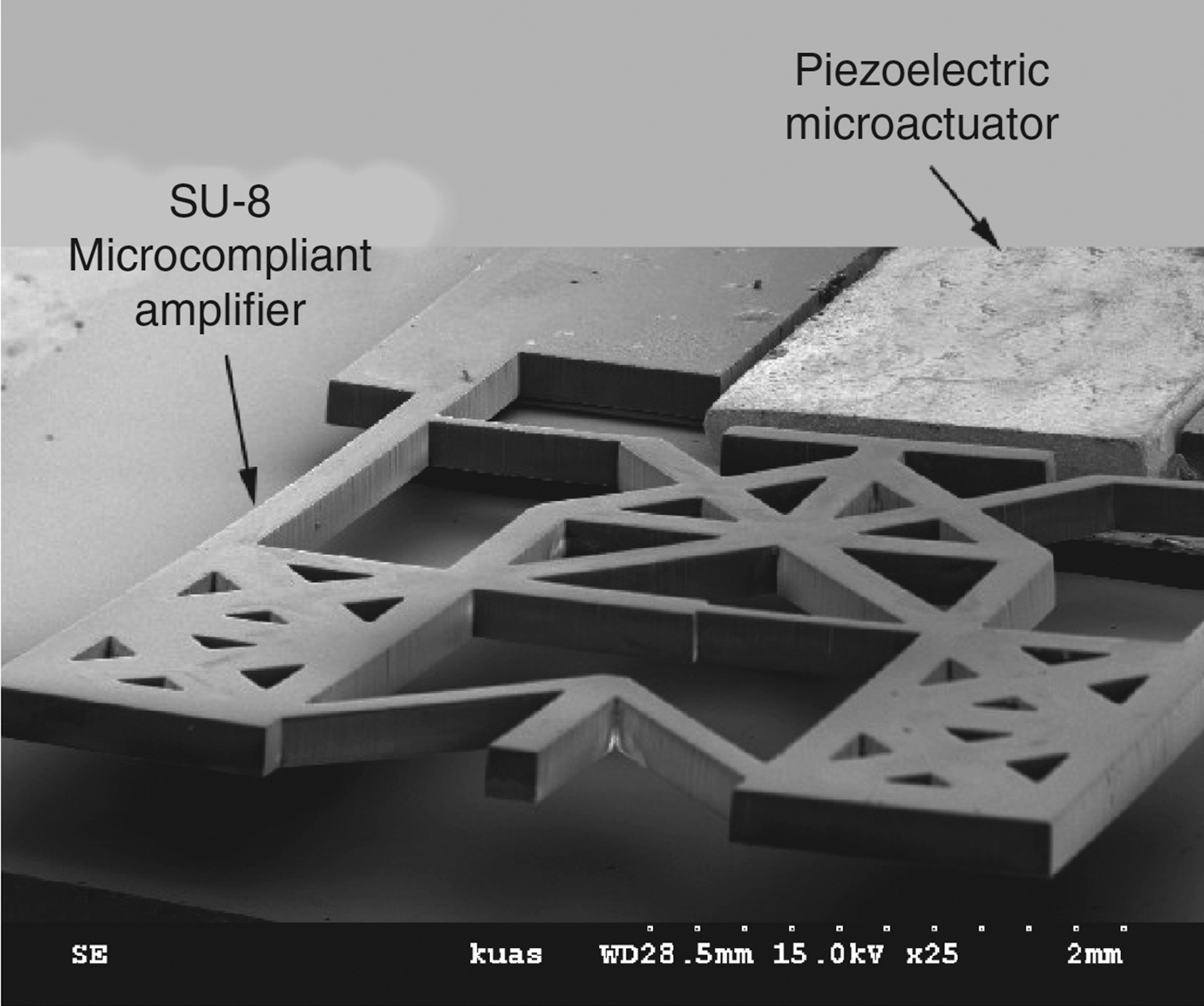
Figure 12.23 Scanning electron microscope image of a piezoelectric microactuator with micro-compliant amplifier (Huang and Lan, 2006).
12.5.2.3. Compliant mechanism
Compliant mechanisms are monolithic structures that utilize their flexible structures to transmit motion or force from an actuator (Ouyang et al., 2008). For example, a micro-compliant made of SU-8 (Fig. 12.23) with an average amplifier factor of 6.9 has successfully produced ∼15.2 μm and 730 μN at 20 V from a piezoelectric actuator (Huang and Lan, 2006). Large forces from the piezoelectric actuator have been converted into a greater displacement.
12.6. Conclusion
Microactuators have shown a promising future and are important in many fields as the demand continues for highly functional items at a reduced size. This is the case for nanoscale applications, which require tools and processes that are capable of precisely positioning and manipulating nanoscale components and materials. This chapter reviewed the state-of-the-art in microactuators and related issues, examining design, fabrication, and integration with ICs. Basic working principles, design considerations, the selection of different transduction mechanisms for operation, and design optimization were discussed. It should be noted that different transduction mechanisms have their own unique attributes. Occasionally, combination of different transduction mechanisms in a single application is required to achieve optimal result (Du et al., 2015).
With the relentless increase in enabling technologies, the MEMS foundry services offered to designers will continue to expand. However, the difficulty of matching the current and future needs of the MEMS designer with the limitations of commercial MEMS foundry processes should not be underestimated. For example, many designs that have been demonstrated were custom made in laboratories especially for piezoelectric microactuators and they are not yet supported by commercial foundries. This has impeded the growth and employment of piezoelectric microactuators, especially in high-speed, low-power applications, although this type of microactuator has high capabilities.
To gain enhanced performances and compactness, the integration of MEMS with CMOS has become one of the main research interests in this field because the performances of microactuators have been significantly enhanced via novel designs and optimizations thanks to better understanding of the characteristics of microactuators. Most of the micromachining processes available have been shown to be compatible with standard IC technologies. A considerable number of breakthroughs have been achieved in this matter. Shortcomings of a particular technique were identified and a solution was found to overcome them. Again, it is the piezoelectric microactuators that need further research and investigation. Although alternative materials (e.g., AlN) have been found to be fully compatible with current CMOS fabrication processes, piezoelectric capability needs to be improved.
..................Content has been hidden....................
You can't read the all page of ebook, please click here login for view all page.