
16
Microelectromechanical systems print heads for industrial printing
Abstract
With the recent prospect of microelectromechanical systems (MEMS) print heads broadening their applications beyond digital printing for office use into industrial printing for the direct patterning of micro/nano devices and circuits, MEMS print heads have attracted renewed attention as a key player for realizing printed electronics. Cost-effectiveness, flexibility, and environmental friendliness in fabrication are the main drivers of industrial printing. This chapter introduces MEMS print heads—especially, a new type referred to here as the electrohydrodynamic (EHD) print head. This has emerged recently as a viable and even better alternative to the conventional piezoelectric MEMS print heads for industrial printing, as it offers a higher resolution and thickness of patterning and can eject a high viscosity of ink. Nowadays, not only EHD droplet ejection but also the EHD printing system for industrial applications is being investigated intensively with commercialization in mind. Furthermore, performance indices such as repeatability and stability are becoming a major issue to solve. This chapter also addresses briefly the effort to improve such reliability related indices.
Keywords
Ejection; Electrohydrodynamic (EHD); Inkjet; MEMS; Print
16.1. Introduction
In the past several decades, the generation and ejection of microfluid droplets has been a subject of intensive investigation with its primary R&D objective being in the development of inkjet printing. Recently, there has been a tremendous surge of interest in diversifying the application of microfluid droplet ejection in such a way as to meet a variety of physical, chemical, biological, and engineering needs. For instance, the need for fine printing or microdispensing of a subnano or a subpico liter volume of functional fluids has arisen because of the need for the cost-effective fabrication of high sensitivity in sensing elements, for direct patterning of micro/nano devices and circuits, and for carrying out large-scale combinatorial chemistry assays using expensive chemicals, to name but a few. The impending prospect that the technology for printing micro/nano fluid droplets is to serve as a key enabling technology for the coming printed electronics era can be seen in the heightened viability of directly fabricating sensors, printed circuit boards (PCBs), thin film transistors (TFTs), displays, and biochips on flexible substrates. As the industrial application and commercial viability of micro/nano droplet ejection become more of a reality, performance measured by droplet size, jetting frequency, nozzle array density, and the uniformity of ejected droplets become major concerns so as to satisfy the criteria for the particular industrial application under consideration (Lee et al., 2008).
The technology of direct patterning based on an inkjet print head, possibly fabricated by microelectromechanical systems (MEMS) technology, is now attracting attention because of its potential to replace the existing semiconductor fabrication process for many industrial applications. The conventional patterning based on semiconductor fabrication processing has to go through many steps for the formation of an active pattern because of the required deposition and etching processes with masking, as shown in Fig. 16.1. Direct patterning using an inkjet print head can radically reduce the processing steps as illustrated in Fig. 16.1 because it can selectively and directly form active patterns on substrates, as if writing letters or printing shapes directly on paper. As a result, processing costs are much lower than those of the conventional fabrication process because of the decrease in materials loss, the elimination of the need for masks, and the shortening of processing time. Furthermore, it not only makes patterning large areas easier but also provides an environmentally friendly process with a dramatic reduction in harmful materials from deposition and etching (Sirringhaus et al., 2000; Singh et al., 2010).

The advantages of the print head-based direct patterning over the lithography-based traditional patterning have attracted significant attention from both industry and academia. In particular, the application of MEMS print heads to processes in industrial printing has drawn much attention to the development and commercialization of printed electronics.
As far as MEMS print heads are concerned, thermal-bubble and piezoelectric print heads have already achieved considerable commercial success in digital printing for office use (Bharathan and Yang, 1998; Le, 1998).
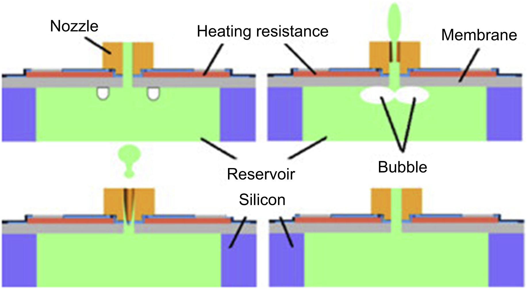
The thermal-bubble print head is currently the most successful print head in the office market. As shown in Fig. 16.2, when the ink supplied from the chamber is heated in the nozzle to several hundred degrees Celsius, bubbles are generated in the ink: the expansive force generated from the bubbles is used to push the ink through the nozzle, ejecting droplets of ink. The vacuum created as the bubbles draw replacement ink into the nozzle, generating a continuously forming supply of droplets (Allen et al., 1985; Chen et al., 1997). As the system is simple and the process is very easy and highly stable, it has been applied to Hewlett–Packard and Canon ink cartridges for inkjet printers (Calvert, 2001). However, the small- and low-density nozzle array and ejection frequency required for thermal-bubble jetting incurs thermal problems when applied to industrial fabrication. Also, ink contains various solvents that can be severely compromised, as the thermal-bubble print head applies direct and considerable heat to the ink over a short time span (Ishida et al., 2005; Choi et al., 2008).
As heat levels cause serious problems in industrial printing for thermal-bubble print heads, research is being pursued on piezoelectric print heads. The piezoelectric print head (Fig. 16.3), first developed by Philips, pushes the ink from the chamber to the nozzle by means of the pressure caused by the vibration of the piezoelectric device situated behind the nozzle, thereby forming ink droplets. In particular, as the vibration of the piezoelectric device can be controlled by electrical signals, a piezoelectric print head can generate very tiny droplets by precisely adjusting small volumes of ink (Le, 1998; Wijshoff, 2010). Furthermore, as the ink is pushed by the pressure of the piezoelectric device vibration instead of using heat, the ink is not compromised. Moreover, it is possible to obtain a very high rate of ejection because of the ease with which low-voltage electrical signals can be input. For these reasons, Epson and other companies are now applying it to office printers (Le, 1998; Calvert, 2001).
Therefore, the piezoelectric print head has been commercialized for industrial printing. The image of a representative piezoelectric printing system made by FUJIFILM Dimatix Inc. is available from URL: http://www.fujifilmusa.com/products/industrial_inkjet_printheads/index.html.
The piezoelectric print head, however, cannot vary the size of droplets produced by a single nozzle; and also, there is a limit to the dimensions to which a nozzle can be reduced regarding high-resolution patterns, as the size of the droplet is proportional to the size of the nozzle. Furthermore, reducing the nozzle size to create microdroplets requires a reduction in the size of the piezoelectric device, leaving it unable to create sufficient force to eject the droplets. As nozzle density is difficult to increase, there is a limit in the degree of its integration. Moreover, there are many limitations when producing industrial ink because the pressure from the vibration of the piezoelectric device is insufficient to eject inks that are highly viscous (Ishida et al., 2006; Byun et al., 2008; Lee et al., 2008).
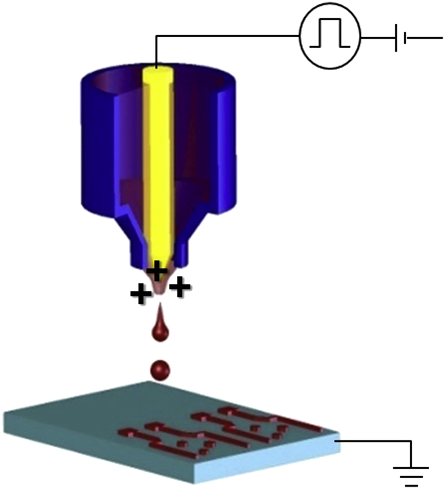
As an alternative to the thermal-bubble and the piezoelectric print heads and their attendant shortcomings, electrohydrodynamic (EHD) jetting, based on the direct manipulation of liquid by an electrical field, appears more promising. The EHD print head forms droplets by applying a high voltage, thus drawing ink to the nozzle, as shown in Fig. 16.4. In an electrical field, an electric charge is induced on the surface of the meniscus of the ink and electrical stress stretches the meniscus toward the direction of the field. An electrostatic field draws the meniscus of the liquid into a sharp cone, and charged liquid droplets are ejected from the nozzle when the electrostatic forces exceed the forces of the surface tension. Depending on the static biasing field, the duration and amplitude of the electric pulse, and the physical properties of the liquid (such as surface tension, viscosity, electrical conductivity, and dielectric constant), this device can generate a spray, a continuous stream, or, under special conditions, discrete monodisperse droplets (Kim et al., 2007; Lee et al., 2008).
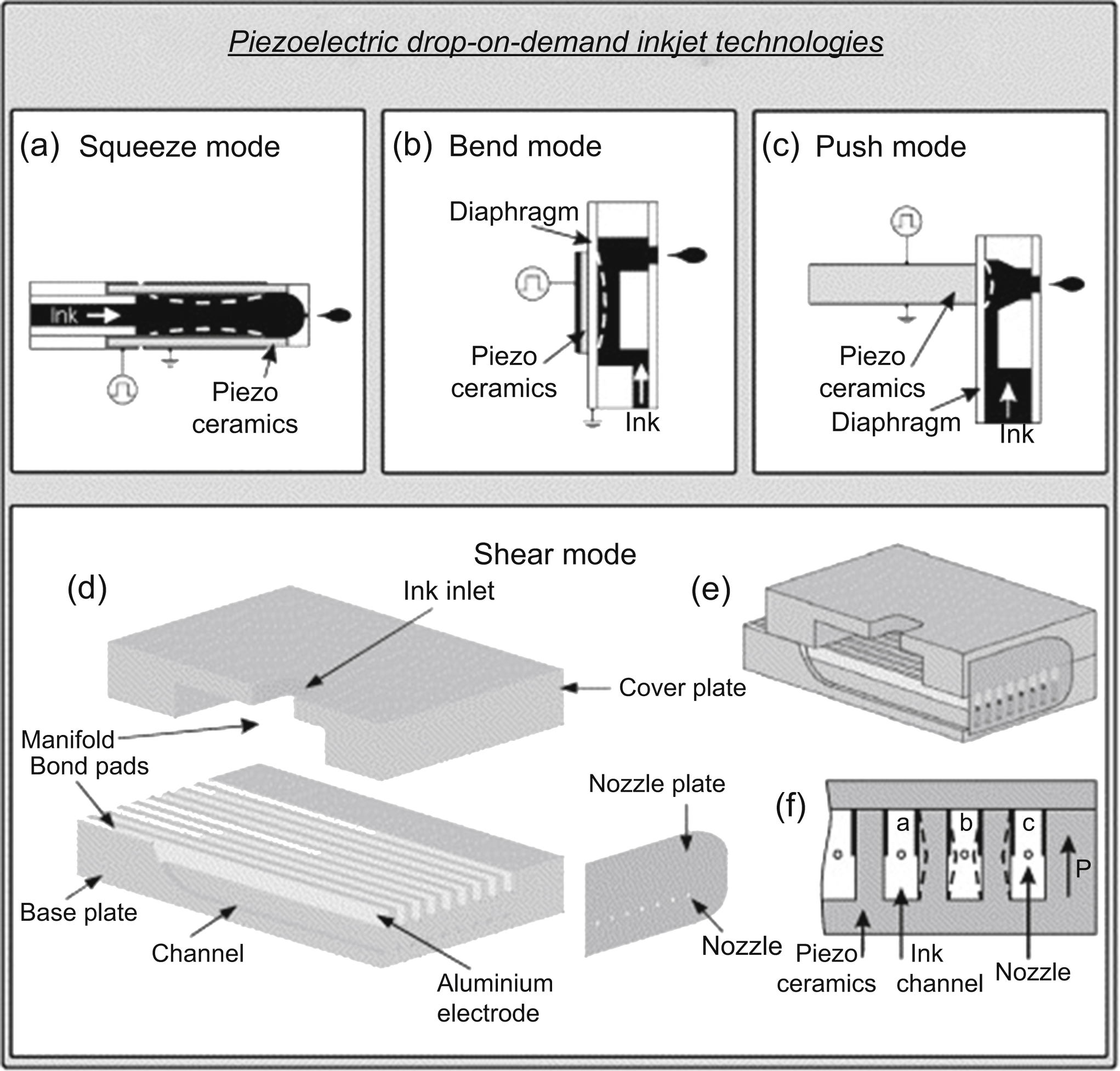
Figure 16.3 (a–f) The piezoelectric print head. From Brünahl, J., Grishin, A.M., 2002. Piezoelectric shear mode drop-on-demand inkjet actuator. Sensors and Actuators A 101, 371–382. Copyright © 2002, Elsevier.
The EHD print head causes no damage to the ink because no heat is generated—one of the major problems with thermal-bubble print heads. Also, the EHD print head can eject highly viscous liquids and increase the degree of integration without any of the fundamental limitations of a piezoelectric device. Furthermore, the EHD print head can make a range of droplet sizes that vary from several μm to several tens of μm in one nozzle because droplets can be formed only at end of the meniscus at the nozzle. Thus, ultrahigh-resolution patterns (∼10 μm) can be deposited on the substrate, which has been impossible to fabricate by any other printing means.
Moreover, the EHD print head can eject highly viscous ink because the ink is pulled by a strong electrostatic force created by the high voltage. Thus, the EHD printer has special characteristics: the ability to administer a wide range of inks and to form micro/nano-sized patterns with high aspect ratios. Finally, array print heads can be manufactured easily because the structure of the EHD printer head is simple.
Therefore, the EHD print head is considered a core technology and has become a crucial fabrication process in the field of industrial applications.
16.2. Electrohydrodynamic print head droplet ejection
EHD droplet ejection based on EHD spray phenomenon is known to be able to generate droplet by electric field and potential. EHD droplet ejection has different ejection modes; however, microdripping mode, pulsed cone-jet mode, and continuous jet mode are the most appropriate ejection modes for generating desired droplet. Hence, EHD print head, which can form droplet using electric field, has various configurations for better droplet ejection results.
16.2.1. Principle of electrohydrodynamic droplet ejection
The EHD spray phenomenon, known as electrospray, has been known for a long time and related studies have been widely performed, mainly focused on the liquid atomization mode.
The EHD spray phenomenon is known to have been discovered by William Gilbert in 1600 (Mottelay, 1922). In the 18th century, Abbot Nollet experimentally showed the division of the main jet into very small jets through the breakup phenomenon by applying a strong electrical field to water. Also, Sir Rayleigh explained the instability of electrified droplets in 1879 (Eggers, 2008), and then Zeleny (1914, 1917) was the first to describe the possibility of droplet jetting by means of an electrical field, conducting an experiment to form droplets and taking pictures of this phenomenon. Since then, studies have continued and many results of droplet ejection have been published regarding various settings and conditions of experiment.
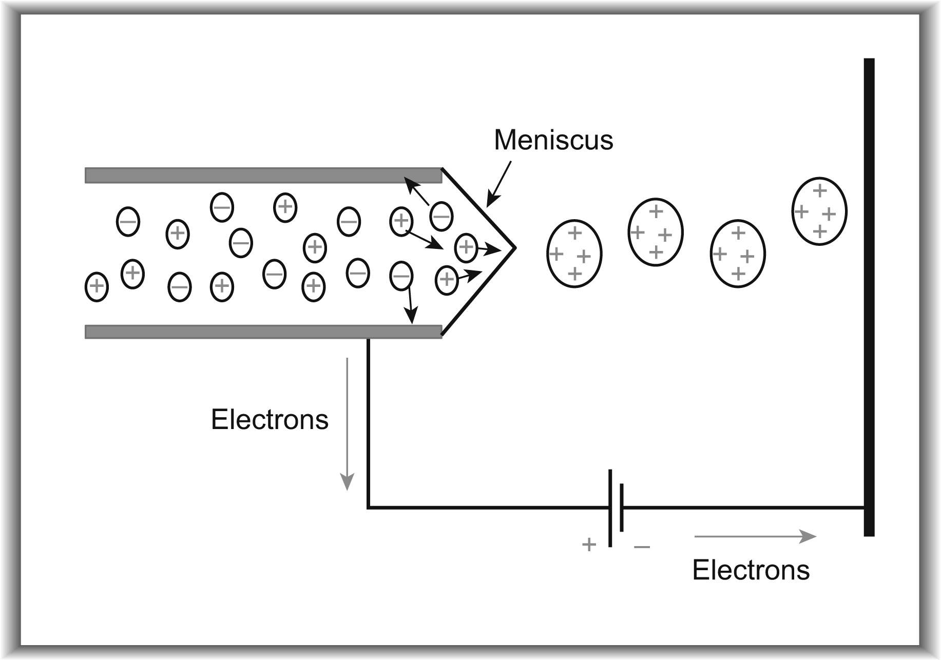
The EHD print head, based on the EHD spray phenomenon that forms droplets through the interaction between electrostatics and fluidics, has the same principle as the EHD spray phenomenon that sprays liquid as tiny droplets by means of an electrostatic field. The basic principle of electrospraying is the electrical physical process. The charges in liquid and ink divided positive and negative ions with electrical characteristics because of the difference of electric potentials between the nozzle and the substrate. Thus, the electrical repulsive forces create the curved surface (meniscus) of the liquid. After that, the positive and negative ions are separated by the strong electrical force in the meniscus, and finally tiny droplets are formed at the furthermost part of the meniscus, as shown in Fig. 16.5 (Wilhelm, 2004).
Based on the EHD spray phenomenon, many studies have been conducted to form one droplet and to control the EHD droplet ejection. Several researchers have attempted to manufacture an EHD print head that generates monodisperse droplets for the general purpose of MEMS print heads (Lee et al., 2008). Thus, the results of EHD droplet ejection offer the basic foundation for the development of the EHD print head, and a wide range of experiments with droplet ejection have been conducted. Section 16.2.2 discusses this in greater detail.
Many researchers have developed an EHD droplet ejection prediction and simulation model to demonstrate and explain EHD droplet ejection. The representative references (Smith, 1986; Ganan-Calvo et al., 1997; Notz and Basaran, 1999; Lastow and Balachandran, 2006; Collins et al., 2007; Kim et al., 2007; Li, 2007; Jaworek and Sobczyk, 2008) show various EHD droplet ejection modeling methods.
16.2.2. Various droplet ejection modes
The EHD spray phenomenon, explained in Section 16.2.1, was revealed to have various jetting modes according to the applied voltage and flow rate through a basic experiment for EHD droplet ejection (Cloupeau and Prunet-Foch, 1990). In particular, as shown in Fig. 16.6, the EHD spray phenomenon has different ejection modes depending on initial electric potential. However, ink properties were also revealed to be a major factor affecting ejection (Cloupeau and Prunet-Foch, 1994; Choi et al., 2010). Thus, many studies are being undertaken to define the jetting mode based on ink properties. Also, research findings about droplet ejection pertaining to ink properties—such as surface tension, viscosity, electric conductivity, and the dielectric constant—are helpful in the development of industrial EHD print head inks.
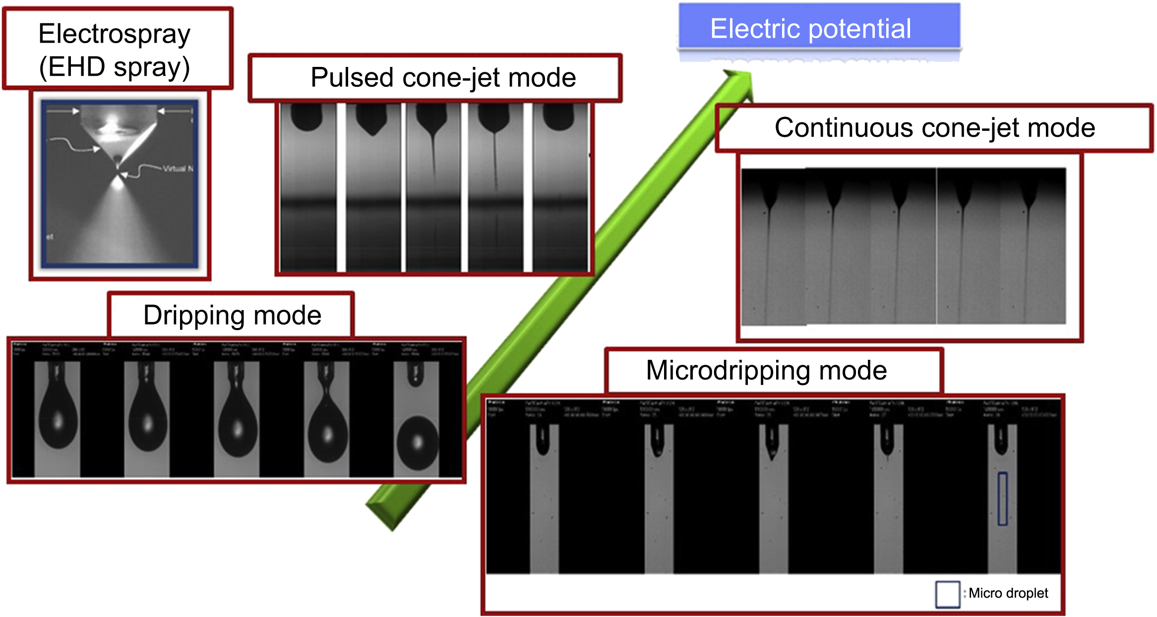

EHD droplet ejection modes can be typically divided into 10 categories (Jaworek and Krupa, 1999). Among them, four modes—the dripping mode, microdripping mode, pulsed cone-jet mode, and continuous cone-jet mode—are suitable for the EHD print head.
The dripping mode, the most basic ejection mode, is very similar to the falling of droplets with no electrical field. Droplets fall when the sum of the gravity and electrical force is greater than the surface tension, and the shape becomes spherical, as shown in Fig. 16.7(a). However, with the dripping mode the pattern size is very large and the patterning process is too slow; this is because of the jetting frequency being too low and the droplet being larger than the outer diameter of the nozzle. Therefore, the dripping mode is inappropriate ejection mode for industrial use of an EHD print head.
The microdripping mode is similar to the dripping mode because it can form tiny spherical droplets; it is also similar to the pulsed cone-jet mode in terms of it forming long jetlike droplets (see Fig. 16.7(b) and (c)). Compared with the dripping mode, however, the microdripping mode and the pulsed cone-jet mode are suitable for the EHD print head because they can form droplets that are smaller than the outer diameter of the nozzle and have a much faster jetting frequency.
In the microdripping mode and the pulsed cone-jet mode, the force of the electrical field at the end of the nozzle is sufficiently large, causing the meniscus to form a hemisphere or ellipse. Droplets that are much smaller than the outer diameter of the nozzle are formed only at the furthermost part of the meniscus, where the electrical field is concentrated. Therefore, the diameters of the droplets range from several μm to several hundred μm, and the size distribution of the droplets is generally even. Furthermore, the ejection frequency of the droplets ranges from several tens of Hz to several tens of kHz.
The continuous cone-jet mode is the basic method for EHD ejection. The jet formed by the meniscus is ejected continually without stopping and cutting, unlike in the pulsed cone-jet mode, as shown in Fig. 16.7(d). Thus, frequency of ejection is almost infinite and the diameter of the jet is very small, so that when jet is printed on substrates, it can make submicron or micropatterns.
Therefore, the microdripping mode, pulsed cone-jet mode, and continuous jet mode are certainly the most appropriate for industrial manufacturing processes.
16.2.3. Configuration of the electrohydrodynamic print head
As with the conventional MEMS print heads (i.e., the thermal-bubble and piezoelectric print heads), the EHD print head basically consists of a nozzle, a chamber for storing ink, and a pressure or flow regulator that supplies ink to the nozzle and controls its volume.
The EHD print head, as mentioned in Sections 16.2.1 and 16.2.2, forms droplets using the electrostatic field induced by the high voltage. Thus, EHD print heads are classified into three different types depending on how the electrical field to provide the high voltage is formed between the nozzle, substrate, and electrode.
Fig. 16.8(a) shows a direct EHD print head in which a high-voltage supplier is connected to the nozzle and substrate, the droplets being formed by the difference of electric potential between the nozzle and the substrate. This has the same configuration as Fig. 16.5, which describes the basic principle of the EHD spray phenomenon in Section 16.2.1. The configuration is also identical to that used in electrospraying, which is the most commercialized application of EHD. The direct EHD print head can form droplets by making precise adjustments in the pressure and voltage rather than by producing the EHD spray phenomenon using EHD spray equipment. This configuration is used in the simplest EHD print head and has been employed to set up the initial experiments on the EHD spray phenomenon. As it is easy to experiment with this printer head using submicron nozzles, high-resolution patterns using the direct EHD print head have been reported (Park et al., 2007).
Fig. 16.8(b) shows a gate electrode EHD print head in which a gate electrode is positioned between the nozzle and the substrate, and droplets are formed by the difference of the electric potential between the nozzle and the gate electrode, with no electrical influence from the electrical field. When the jet (whether cone or pulsed cone) is ejected, however, most of the jet is divided into small droplets that are similarly sprayed after they pass through the electrode. Thus, studies are being conducted to solve this problem by adjusting the geometries of the electrode, substrate, and applied voltage (Choi et al., 2007).
Finally, Fig. 16.8(c) shows an EHD print head with a microtip configuration wherein a conical electrode (microtip) is positioned under the substrate. In this head, the conical electrode concentrates the electrical field on the meniscus, so the conical electrode is placed in line with the nozzle and the z-axis. This has greater advantages for patterning because a more concentrated electrostatic force can apply to the meniscus compared with a direct EHD print head, as shown in Fig. 16.10(a). If the substrate is dielectric, however, there is no benefit in concentrating the electrical field with a conical electrode.
Moreover, three different types of EHD printing system can be modified for better droplet ejection results (see Ishida et al., 2006; Lee et al., 2007).

16.3. Electrohydrodynamic smart printing system
EHD printing system has recently attracted considerable attention for industrial manufacturing process. The section explains EHD printing system that can control the width and thickness of pattern and ensure repeatability and stability. Also, this section introduces EHD multihead printing system for industrial applications.
16.3.1. Electrohydrodynamic printing system
The EHD printing system requires a high-voltage supplier (∼3 kV) and means with which to supply voltage to the nozzle and the ink. Unlike the conventional thermal-bubble and piezoelectric MEMS printing systems, a droplet is formed from the meniscus in the nozzle by a strong electrical field. Fig. 16.9 shows the prototype of the EHD printing system that connects the nozzle and the ink to the high-voltage supplier.
Drop-on-demand (DOD) ejection is a key in industrial application. To achieve this, the high-voltage supplier should generate an appropriately high voltage (∼3 kV) with a specific waveform rather than providing a constant voltage (i.e., a DC voltage). In other words, the high-voltage supplier must be able to supply 2 kV or higher bias and pulse voltage waveforms; this is essential to make the EHD printing system beneficial for industrial application. Thus, research into and production of a high-voltage supplier with the relevant ejection parameters is as important as research on the EHD print head itself.
Using a high-voltage supplier with bias and pulse voltage waveforms, the DOD ejection of droplets was examined for a deionized water solution with sodium dodecyl sulfate (3 wt%) as shown in Fig. 16.10. A droplet is formed and ejected from the tip of the liquid meniscus in response to the pulse signal. With an applied external pulse of 500 Hz, the droplet is generated in accordance with the frequency. When a 1.1 kV pulse is applied based on a 1.4 kV bias voltage, the liquid meniscus is extracted from the tip of the nozzle and forms a cone shape. At the end of the pulse, the tiny droplet is broken from the apex of the meniscus and the remaining liquid is retracted. If the physical properties of the liquid (such as viscosity, surface tension, electric conductivity, and dielectric constant) are fixed and the optimal pulse and voltage are controllable, the DOD jetting system is feasible (Lee et al., 2008).
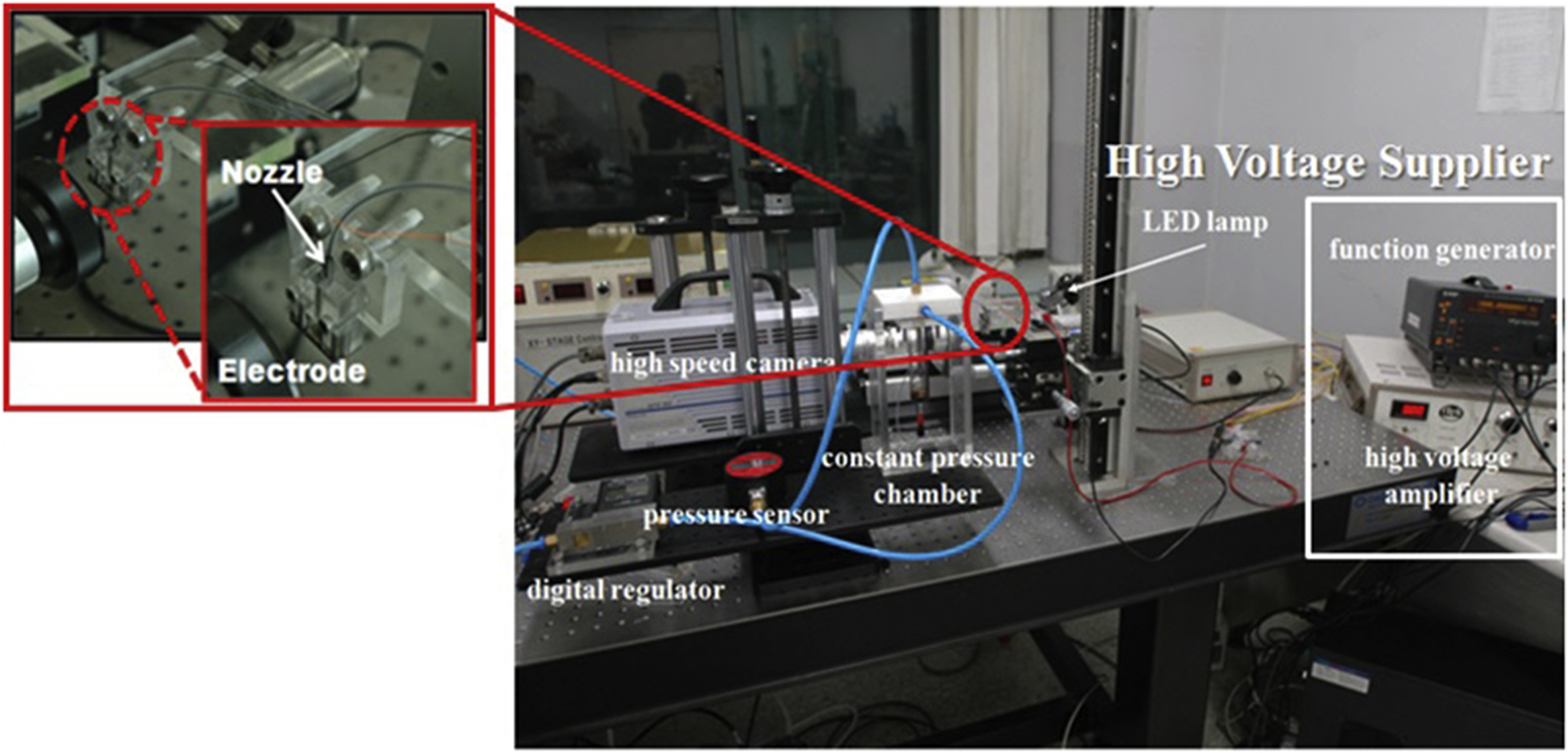
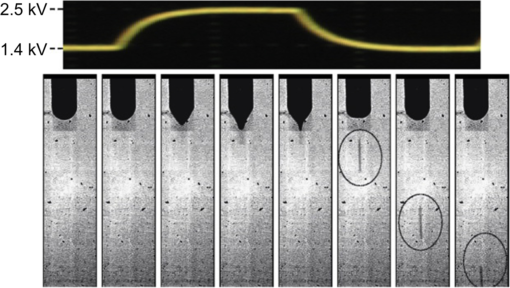
Figure 16.10 Drop-on-demand ejection characteristic using high-voltage supplier at operating frequency of 500 Hz and duration of 0.2 ms. From Lee, S., Byun, D., Jung, D., Choi, J., Kim, Y., Yang, J.H., Son, S.U., Tran, S.B.Q., Ko, H.S., 2008. Pole-type ground electrode in nozzle for electrostatic field induced drop-on-demand inkjet head. Sensors and Actuators 141, 506–514. Copyright © 2008, Elsevier.
Based on a feasibility study, Choi et al. (2008) demonstrate the characteristic and patterning result of DOD ejection using a high-voltage supplier with bias and pulse voltage waveforms. Fig. 16.11 shows the DOD ejection characteristic as controlling applied bias and pulse voltage, frequency, duty cycle, and flow rate; Fig. 16.12 shows the scanning electron microscope images of dots and lines produced with DOD ejection (Choi et al., 2008).
To realize an EHD printing system capable of performing various patterning processes, as with conventional printing systems, the EHD system needs linear motors that can move the substrate and the EHD printing device in the direction of the x, y, and z axes. Also required are a vision system for the layered patterning and a control system that ensured compliance with the required print specifications. In particular, the system requires devices and programs to analyze the formation of droplets and patterns on the substrate through image processing and to control the transport speed and location of the substrate using information from the linear motor and high-voltage supplier. Many research organizations and companies have recently developed EHD printing systems that satisfy these basic conditions and are selling them for EHD printing experiments and pattern formation. Fig. 16.13 shows typically commercialized EHD printing systems.
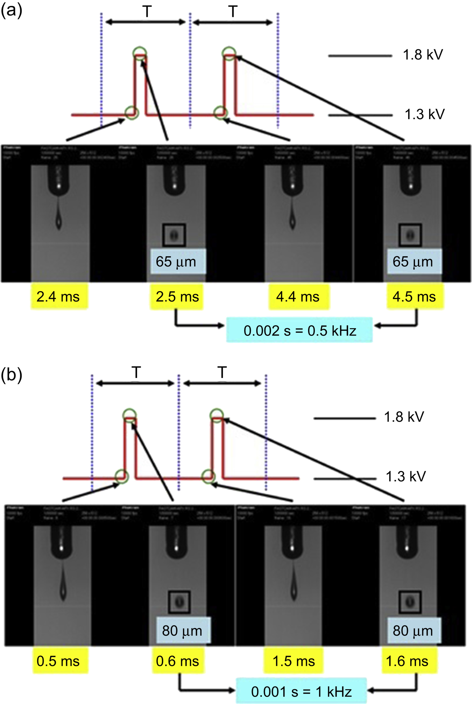
Figure 16.11 Jetting images of drop-on-demand results using conductive nanosilver ink: (a) 0.5 kHz and 5 μL/min and (b) 1 kHz and 15 μL/min. Modified from Choi, J., Kim, Y., Lee, S., Son, S.U., Ko, H.S., Nguyen, V.D., Byun, D., 2008. Drop-on demand printing of conductive ink by electrostatic field induced inkjet head. Applied Physics Letters 93, 193508.
16.3.2. Control of the pattern resolution and thickness
The parameters for controlling the pattern resolution and thickness of the EHD printing system are the nozzle/substrate (electrode) geometry, electrostatic field strength, ink properties, properties of the substrate surface, patterning repetition, and motor velocity.

Figure 16.12 Scanning electron microscope images of dot and line patterning results at drop-on-demand ejection: (a) 0.5 kHz and 5 μL/min and (b) 1 kHz and 15 μL/min. Modified from Choi, J., Kim, Y., Lee, S., Son, S.U., Ko, H.S., Nguyen, V.D., Byun D., 2008. Drop-on demand printing of conductive ink by electrostatic field induced inkjet head. Applied Physics Letters 93, 193508.
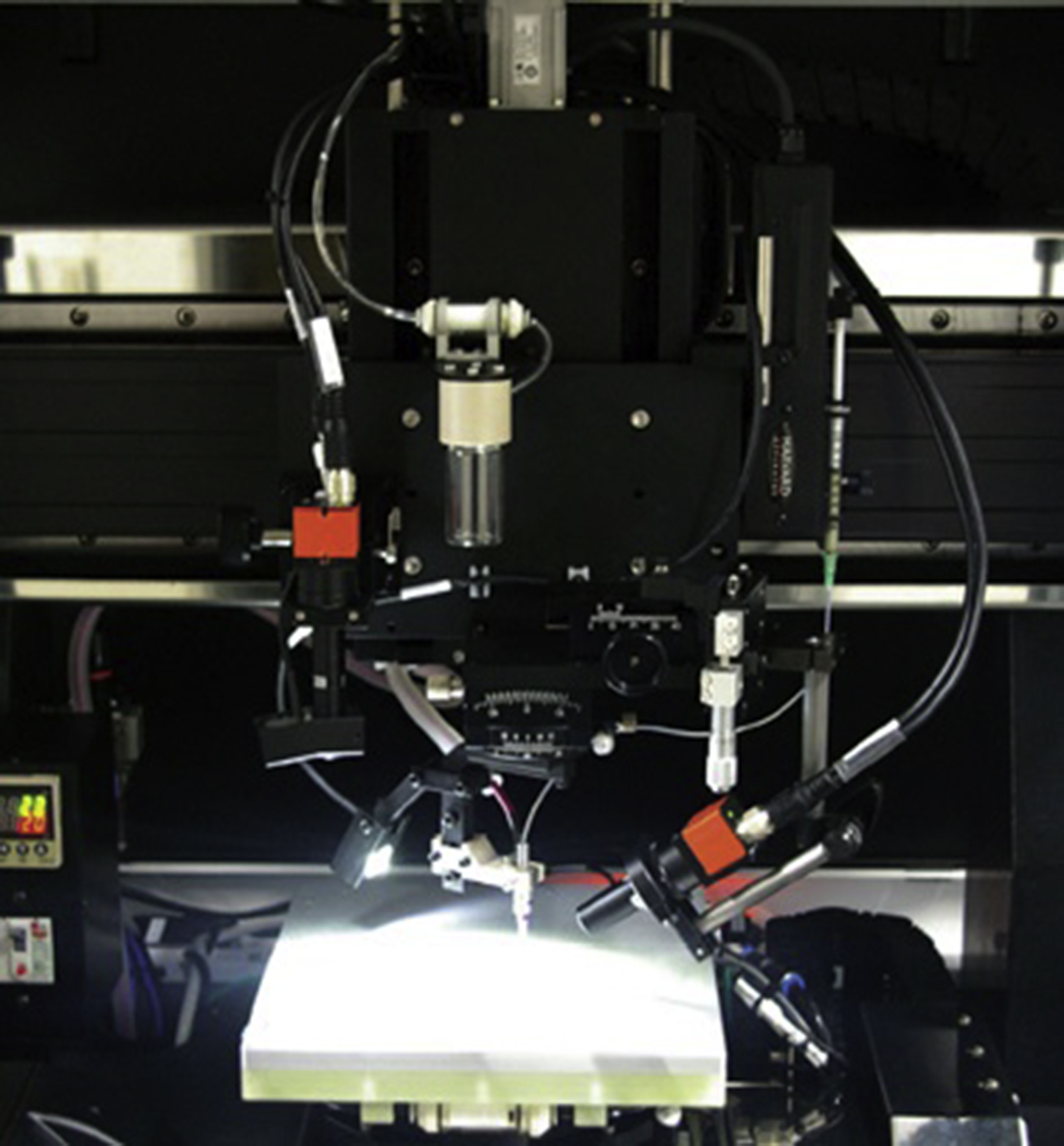
Figure 16.13 The commercialized electrohydrodynamic printing systems by ENJET Co. From ENJET Co. brochure. Available from: http://www.enjet.co.kr/index.html.
Although the EHD printing system can eject droplets of various sizes from a single nozzle in response to the supplied voltage, it cannot actually jet submicron droplets and patterns in a nozzle with a diameter of 100 μm. Therefore, the nozzle should be smaller to enable submicron patterning, which is one of the strong points of the EHD printing system, as shown in Fig. 16.14(a). Also, the pattern sizes of the EHD printing system are influenced considerably by the applied voltage. Increasing the applied voltage causes an increase in pattern volume, as shown in Fig. 16.14(b). In addition, pattern width and the scattering effect of pattern are affected by the distance between the nozzle and the substrate (or electrode) because the electrical field applied to the meniscus can be varied depending on the distance between the nozzle and the substrate (or electrode). Therefore, the design of the nozzle/substrate (electrode) geometry is important to achieving the desired patterning.
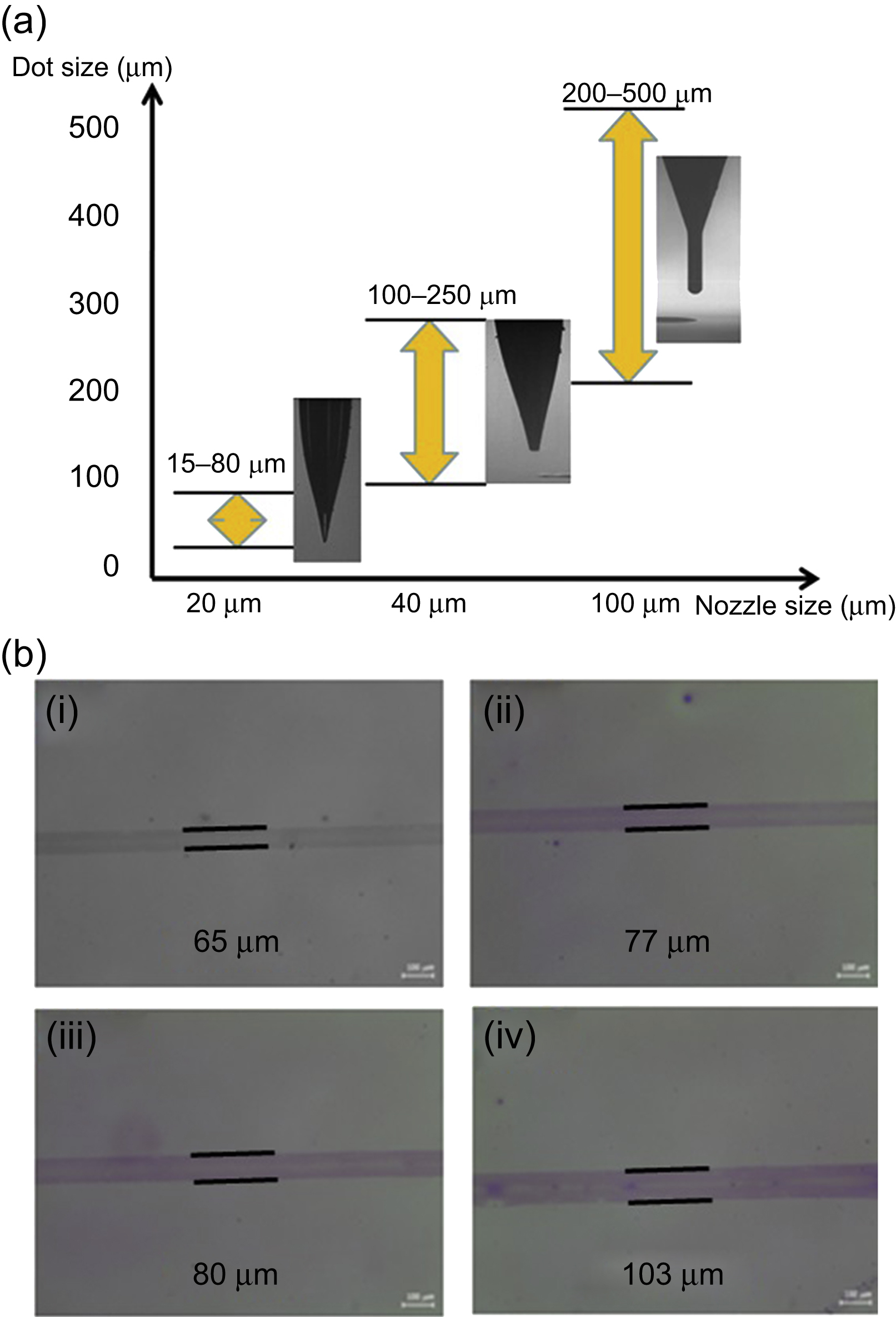

Figure 16.15 (a) Patterns on hydrophobic and hydrophilic substrates and (b) the jetting image of ink with ∼12,000 cP. Modified from Jayasinghe, S.N., Edirisinghe, M.J., 2004. Electrically forced jets and microthreads of high viscosity dielectric liquids. Aerosol Science 35, 233–243. Copyright © 2004, Elsevier.
The EHD printing system also forms patterns as droplets are rapidly deposited on the substrate, as is the case with thermal-bubble and piezoelectric printing systems. Thus, the surface energy determines the degree to which the droplets spread on a substrate. Therefore, as shown in Fig. 16.15(a), the pattern on a hydrophobic substrate is smaller and thicker than the pattern on a hydrophilic substrate. Also, through patterning repetition reprints on printed patterns, not only can thick patterns be obtained but also the thickness of the patterns can be controlled.
Finally, the EHD printing system has a larger range of ink viscosity. Therefore, the EHD printing system can eject inks of a higher viscosity and form thicker patterns with them than with conventional printing systems. Fig. 16.15(b) shows the ejection of a highly viscous ink (∼12,000 cP) (Jayasinghe and Edirisinghe, 2004).
Also, repeated duplications in EHD printing are effective method for forming a high aspect ratio of metal lines. As the number of repeated duplication increases, aspect ratio of metal lines increases as shown in Fig. 16.16 (Son et al., 2013).
16.3.3. Repeatability and stability
The repeatability and stability of droplet ejection and patterning in the EHD printing system are important factors for applying the system to industrial manufacturing processes. To ensure repeatability and stability, the meniscus should not reach the outer nozzle and the movements should be fixed in the repeated ejection process. To establish the shape of the meniscus without modifying the nozzle, hydrophobic materials are applied externally to the nozzle. Fig. 16.17 depicts stable ejection where the meniscus does not overflow on the outer part of the nozzle. The hydrophobic nozzle has the advantage of ejecting droplets by retaining the meniscus shape at the moment of ejection because of the relatively large contact angle of the hydrophobic nozzle surface, as shown in Fig. 16.17(a) and (b) (Kim et al., 2010).
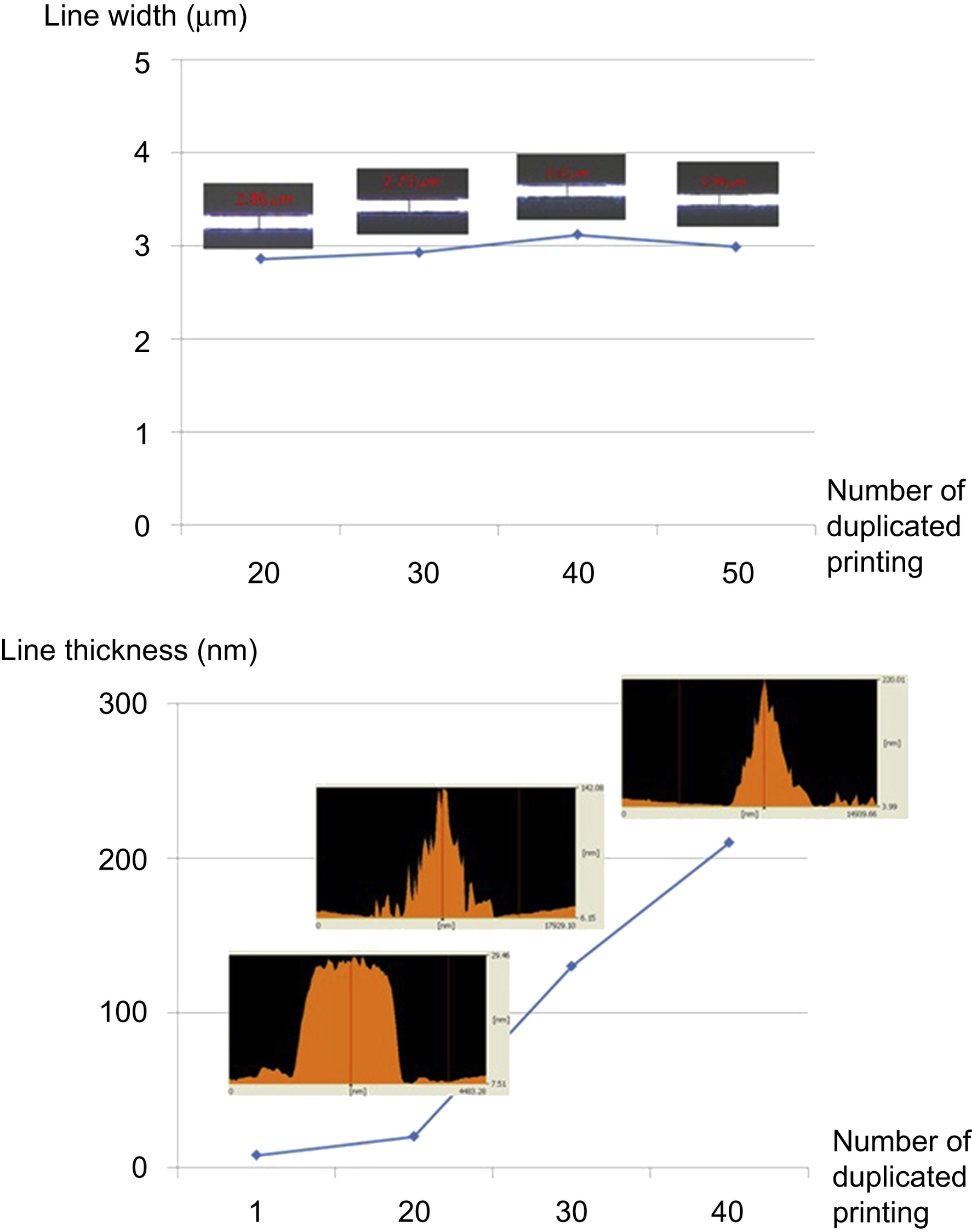
Figure 16.16 The variation of line width and thickness by the number of duplicated printing. From Son, S., Lee, S., Choi, J., 2013. Repeated duplication in EHD line patterning on a non-conductive substrate based on controlling the polarity of applied voltages. NSTI-Nanotech 2013, 12–16 May 2013, Washington DC, USA, pp. 273–276.
Fig. 16.18(a) also shows that the EHD printing system can offer excellent performance regarding repeatability and stability without overflowing and damping at the meniscus on the nozzle. The nozzle includes a concave section formed along its outer circumference to ensure repeatability and stability (Kim et al., 2013).
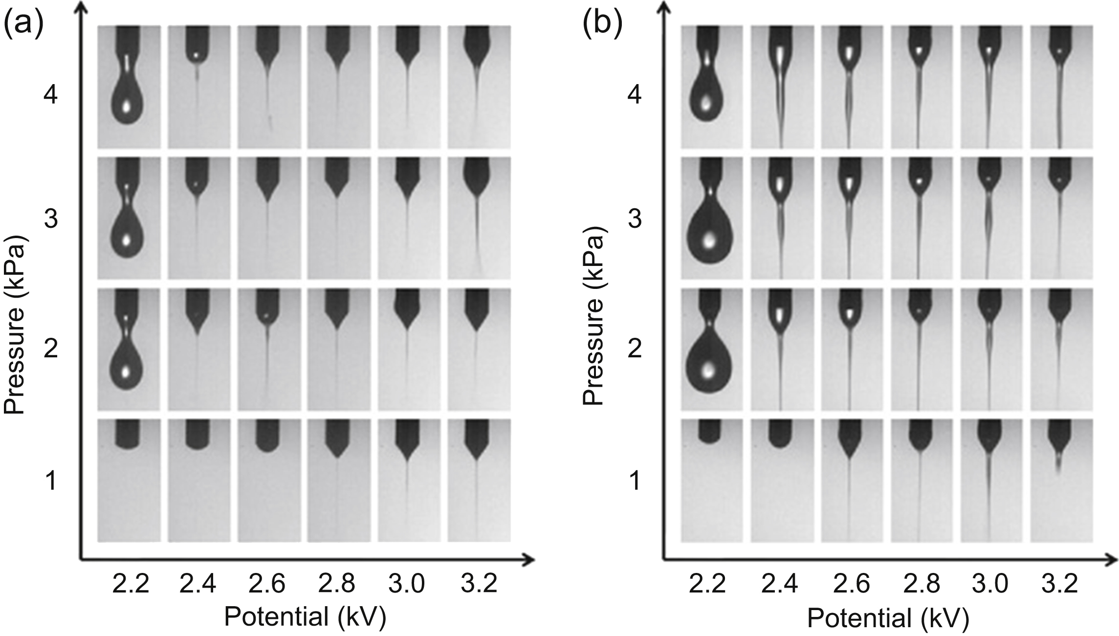
Figure 16.17 The moment of ejection and meniscus shape images: (a) hydrophobic nozzle and (b) hydrophilic nozzle. Modified from Kim Y.J., Choi J., Son S.U., Lee S., Nguyen X.H., Nguyen V.D., Byun D. and Ko H.S., 2010 Comparative study on ejection phenomena of droplets from electrohydrodynamic jet by hydrophobic and hydrophilic coatings of nozzles. Japanese Journal of Applied Physics 49, 060217.
The effects of various pulse voltages, frequencies, duty cycle, and pressures for meniscus deformation and ejection were investigated to find the optimal region for EHD DOD printing. The research showed that the restoration time of the meniscus applied to the pulse voltage is an important factor of EHD DOD printing regarding the relationship between the pulse voltage and the frequency (Son et al., 2010).
Droplets themselves have electrical charges because they are formed by the electrostatic force in the EHD printing system. The electrical charges in the droplets cause the repulsive force between the substrate and the droplets. Thus, droplets cannot remain straight on the substrate and form a pattern at the exact place when the droplets are patterned on substrates, especially a dielectric substrate such as pure glass wafer (Son et al., 2014b). Therefore, many studies are being conducted to remove the electrical charge from a substrate; alternatively, the distances and applied conditions between the nozzle, substrate, and electrode are controlled to reduce the charge effect. Fig. 16.18(b) shows improved droplet ejection and patterning where the charge effect has been countered by controlling and optimizing the pulse voltage.
Fig. 16.19 presents a method of suppressing these satellites/sprays by electric discharging based on a gate electrode EHD print head (refer to Fig. 16.8(b)). Charge effect has been decreased by controlling pulse waveform, which means satellite/spray suppression can be achieved when the gate voltage applied has a waveform of negative and positive pulse pair mixed with a fixed gate bias (Lee et al., 2013).
The charge effect is used for accurate jetting and high quality of printing patterns in EHD printing. Fig. 16.20 shows motionless EHD printing and utilizes an array of target microelectrodes that can be selectively connected to a voltage generator. This printing system adjusts the voltage on/off to pattern the droplet on the desired position (Hwang et al., 2016).

16.3.4. Electrohydrodynamic multihead printing system
An EHD printing system with multiple nozzles would shorten fabrication time (tack time) for industrial applications. Thus, the interference of the electrical field between the nozzles must be overcome for EHD multihead manufacture. In other words, if the voltage supplied to form droplets influences the electrical field of the neighboring nozzle, this nozzle will not form droplets because of its changed electrical field. In addition, accurate patterning at the desired location becomes impossible because of a bent jet or droplet, as shown in Fig. 16.21 (Si et al., 2007).
Therefore, study is being undertaken into EHD multihead printing systems that can reduce or remove the interference to the electrical field between the nozzles (Lee et al., 2011). Two representative EHD multihead printing systems are shown in Fig. 16.22(a): the modified gate electrode EHD print head and (Fig. 16.22(b)) the direct EHD multihead print head.
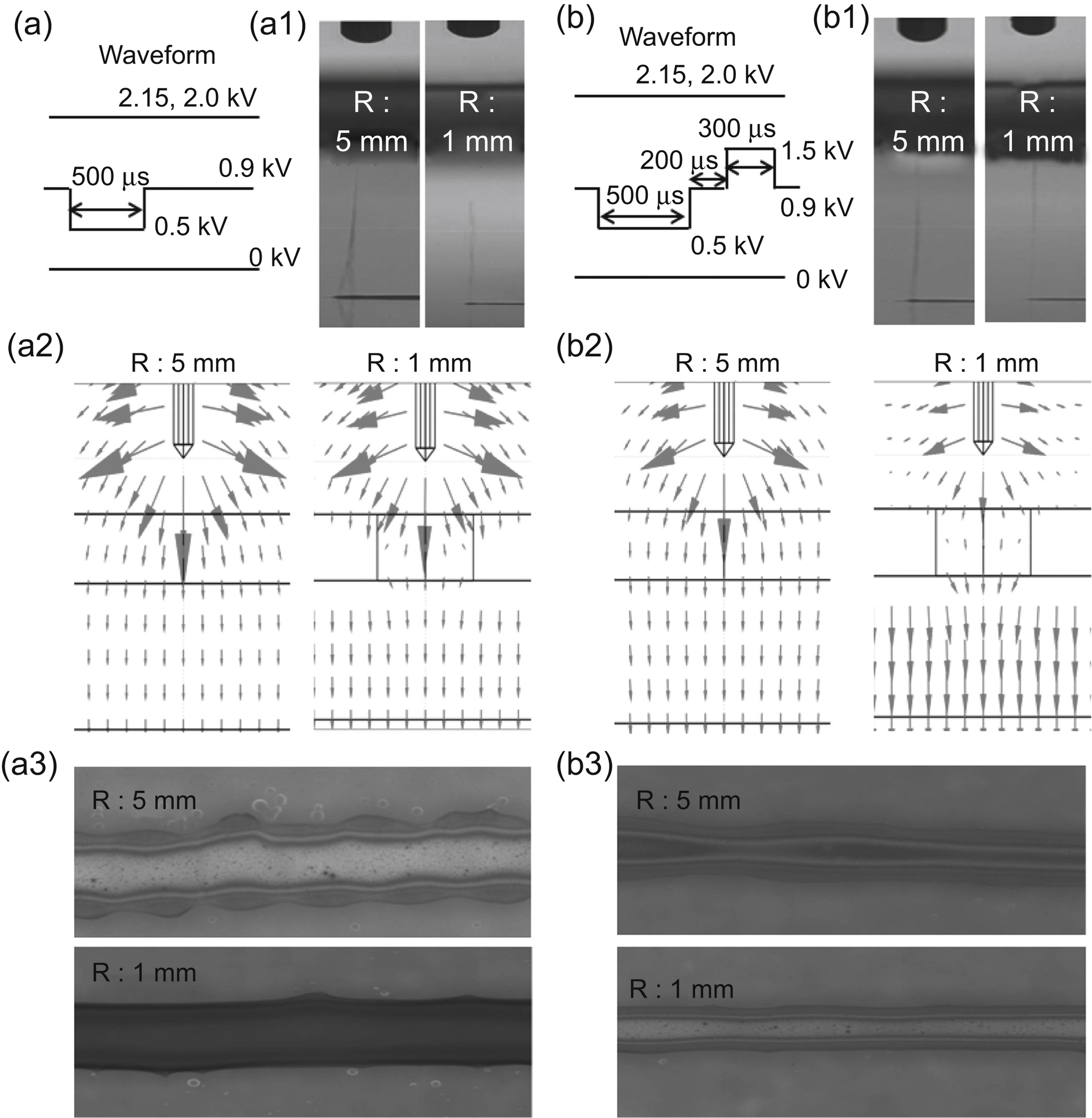
Figure 16.19 (a1–a3) Discharging images, field vector distributions, printed ink patterns, respectively, for R¼5 mm and 1 mm for the pulse waveform of (a). (b1–b3) Discharging images, field vector distributions, printed ink patterns, respectively, for R = 5 and 1 mm for the two-stage pulse waveform of (b). From Lee, S., An, K., Son, S., Choi, J., 2013. Satellite/spray suppression in electrohydrodynamic printing with a gated head. Applied Physics Letters 103, 133506.
16.4. Case study: electrohydrodynamic printing applications
The EHD printing system provides very fine, even submicron-scale printing and jetting, while allowing the adoption of various ink materials—such as metal, organic, and biomaterials with a wider ink viscosity range of thousands of centipoises (cPs). The advantages of EHD printing, further supported by the flexibility and cost-effectiveness of its manufacture, lend themselves to various applications that will be sought in the future—such as the formation and/or repair of fine patterns for flat panel displays, PCBs, flexible electronics, and microbio and -sensor chips. This section introduces the results of application research into the use of the EHD printing system.
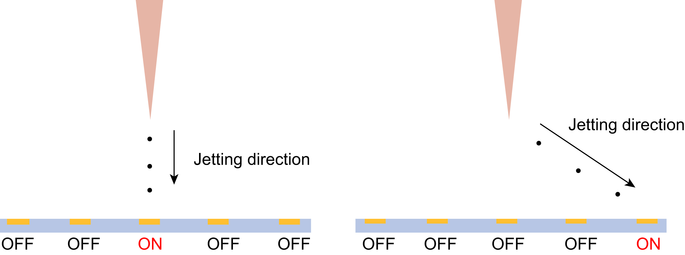
Figure 16.20 A method of motionless electrohydrodynamic jet printing system for patterning on desired position. Modified from Hwang, T.H., Kin, Y.J., Chung, H., Ryu, W., 2016. Motionless electrohydrodynamic (EHD) printing of biodegradable polymer micro patterns. Microelectronic Engineering 161, 43–51. Copyright © 2016, Elsevier.

Figure 16.21 The effect on the meniscus by electrical interference. From Si, B.Q.T., Byun, D., Lee, S., 2007. Experimental and theoretical study of a conejet for an electrospray microthruster considering the interference effect in an array of nozzles. Aerosol Science 38, 924–934. Copyright © 2007, Elsevier.
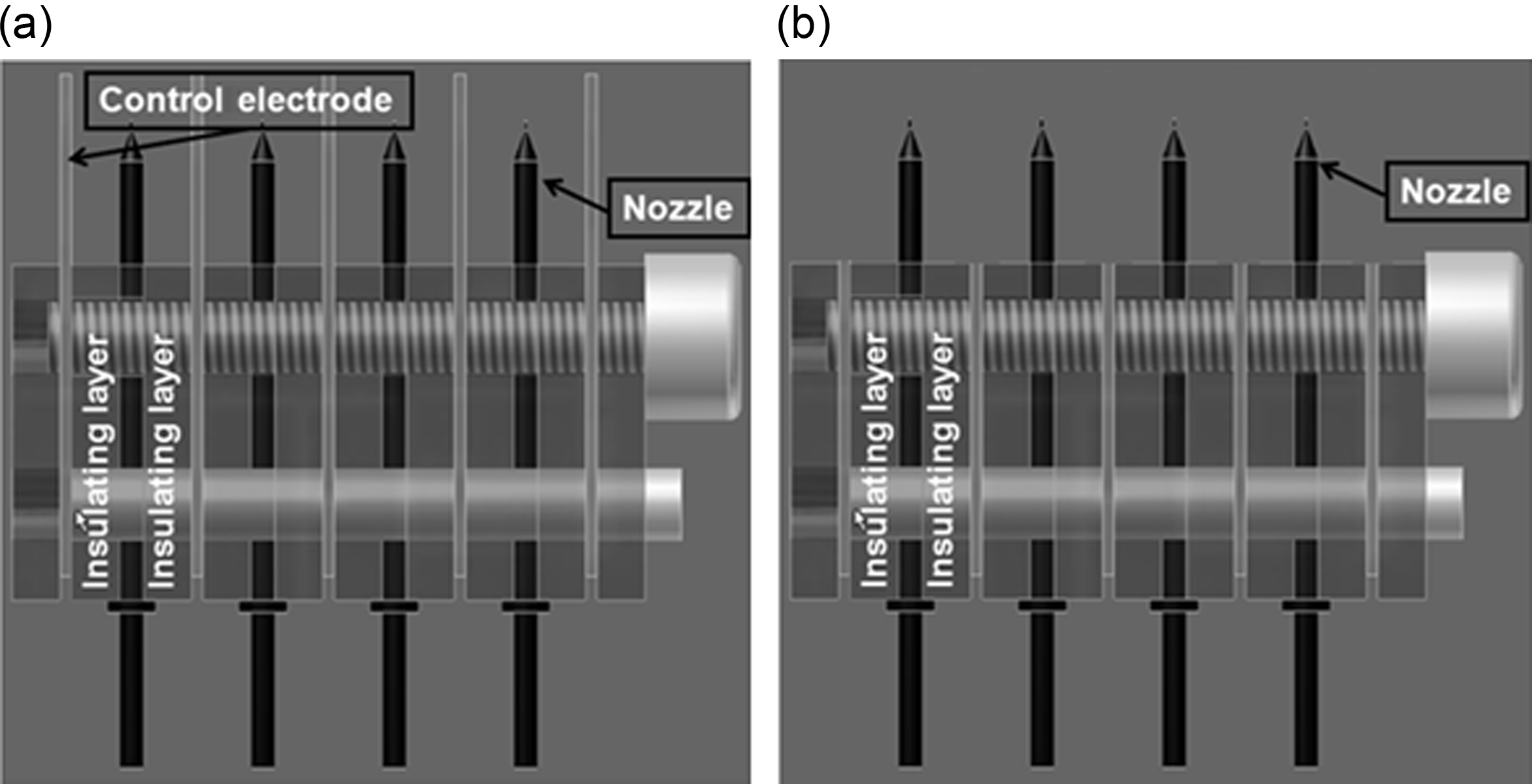
Figure 16.22 Electrohydrodynamic (EHD) multihead printing system. (a) Gate (control) electrode EHD multihead printing system and (b) direct EHD multihead printing system.
Fig. 16.23 shows the circuit pattern with a line width of 3 μm on an untreated substrate using the EHD printing system known as “superfine inkjet printing” (Murata et al., 2005). Fig. 16.23(a) shows a circuit pattern that has a line width of 3 μm and with 10 μm pitches at the lattice area; Fig. 16.23(b) depicts fine wires. Fig. 16.23(c) and (d) present a line width of about 3.6 μm with a line space of 1.4 μm and a line width of about 10 μm with 20 μm pitches, respectively (lines: bright; spaces: dark).
Also, Doyoung Byun at the Sungkyunkwan University fabricated Ag-grid flexible transparent electrode (FTE) with the line width of 4.6 μm using EHD printing system as shown in Fig. 16.24 (Yang et al., 2016). This result for a flexible metal-grid transparent electrode indicates that the Ag-grid FTE is a promising electrode scheme for bendable or foldable electronic devices.
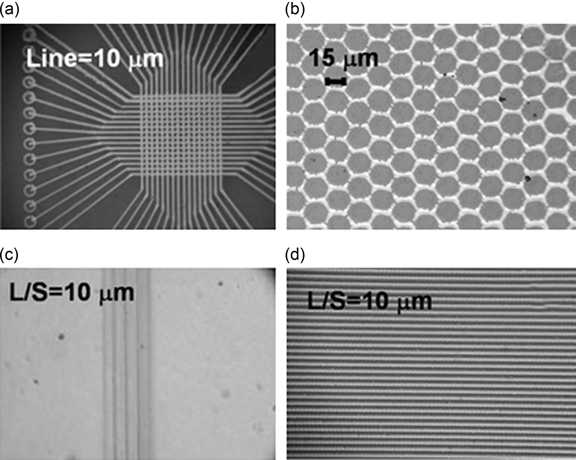
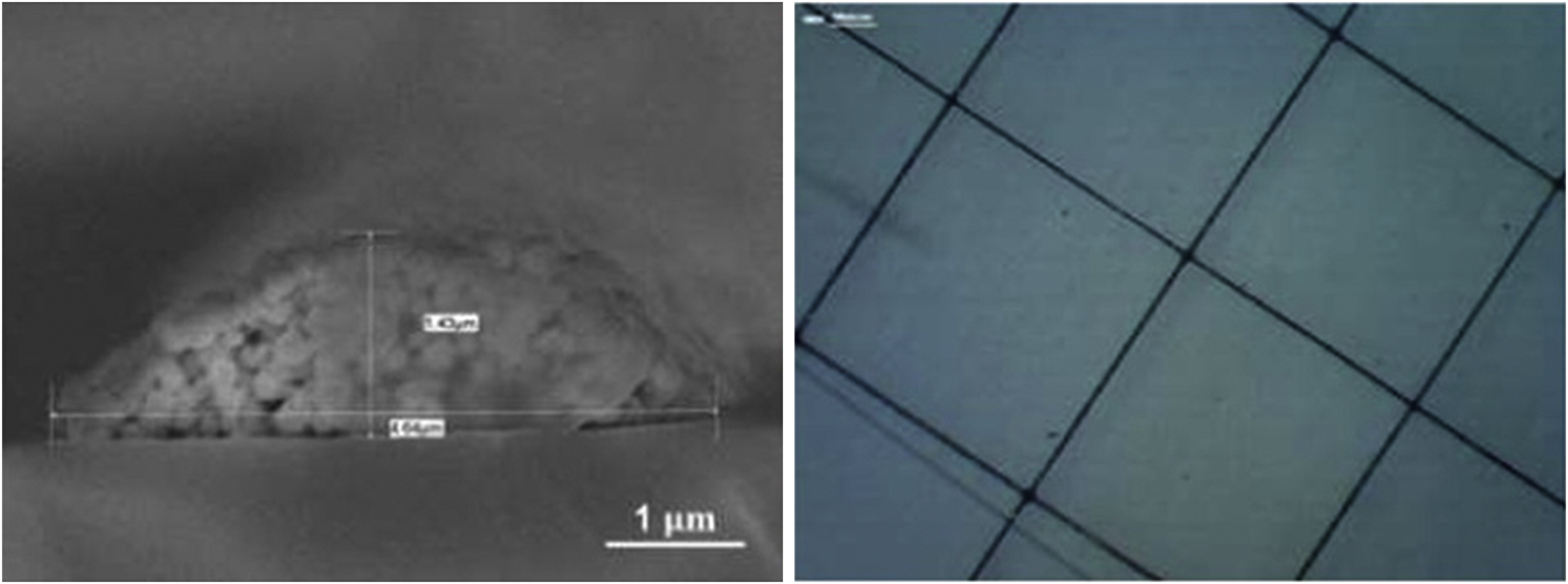
Figure 16.24 The Ag-grid flexible transparent electrode pattern using electrohydrodynamic printing system. Modified from Yang, S.M., Lee, Y.S., Jang, Y., Byun, D., Choa, S., 2016. Electromechanical reliability of a flexible metal-grid transparent electrode prepared by electrohydrodynamic (EHD) jet printing. Microelectronics Reliability 65, 151–159. Copyright © 2016, Elsevier.
John A. Rogers at the University of Illinois at Urbana–Champaign creates complex graphic arts and high-resolution line patterns that can be applied to TFTs and flexible panel displays using EHD jet printing based on the EHD printing system, as shown in Fig. 16.25. This result confirms that the EHD printing system can potentially be applied in various industrial areas (Park et al., 2007).
Fig. 16.26 illustrates line patterning ∼6 μm wide produced by the EHD printing system using a tilted-outlet nozzle and a line pattern with a resistivity of 7 × 10⁻⁶ Ω cm after applying an annealing process. The I–V curves are obtained by the 15 wt% Ag content but the inset figure is obtained by 30 wt% Ag content (Youn et al., 2009).
Fig. 16.27 shows an EHD fine metal line patterning on a hydrophilic nonconductive substrate. This result indicates 3 μm width of metal line patterns with the electrical resistivity of 17.48 μΩ by EHD printing and laser sintering (Son et al., 2014b).
To apply manufacturing electronic devices with EHD printing, many researchers are investigating on a fabrication of electronic devices with high resolution. Fig. 16.28 is an electronic device manufactured by EHD printing as shown in Fig. 16.28(a): high-resolution source/drain electrodes printed In2O3 and Fig. 16.28(b) TFT array printed In2O3 (Kim et al., 2016).
Paul R. Chiarot and Sepehr Maktabi indicated method was used to print organic resistors on flat and uneven substrates. Commercial polymer-based conductive ink poly(3,4-ethylenedioxythiophene)–poly(styrenesulfonate), which has been widely used in the manufacturing of organic electronic devices, has been ejected by EHD printing system for organic polymeric resistors (Maktabi and Chiarot, 2016).
The EHD printing system is attracting considerable attention in the bioresearch field, which requires high-resolution patterns (5–20 μm), because conventional printing systems with thermal-bubble and piezoelectric print heads cannot form high-resolution patterns. Fig. 16.29 shows the fluorescence micrographs of a butterfly pattern using a nozzle with a 2 μm i.d. and an oligonucleotide suspension (37-mer ssDNA labeled with Alexa546). This pattern is composed of arrays of dots 2 μm in diameter (Park et al., 2008).

Figure 16.25 An image and an array achieved by electrohydrodynamic jet printing. The image of a flower was formed with printed dots of a diameter of ∼8 μm diameters; the array is that of source/drain electrode pairs. Modified from Park, J.U., Hardy, M., Kang, S.J., Barton, K., Adair, K., Mukhopadhyay, D.K., Lee, C.Y., Strano, M.S., Alleyne, A.G., Georgiadis, J.G., Ferreira, P.M., Rogers, J.A., 2007. High-resolution electrohydrodynamic jet printing. Nature Materials 6, 782–789. Copyright © 2007, Rights Managed by Nature Publishing Group.
Also, it is challenging to use small molecule inks with EHD printing for high definition and low-cost organic light emitting diode (OLED). Fig. 16.30 presents small molecule ink was printed only on the cells in second, fourth, and sixth rows, and electroluminescence devices were successfully fabricated as expected. Selective red emitting from the electroluminescence device was observed on alternating rows using selective EHD printing and patterning (Choi et al., 2013; Kim et al., 2015).

Figure 16.26 The microscopic nozzle structure of a tilted-outlet nozzle, microscopic image by a tilted-outlet nozzle (∼6 μm), and I–V curves. Modified from Youn, D., Kim, S., Yang, Y., Lim, S., Kim, S., Ahn, S., Sim, H., Ryu, S., Shin, D., Yoo, J., 2009. Electrohydrodynamic micropatterning of silver ink using near-field electrohydrodynamic jet printing with tilted-outlet nozzle. Applied Physics A 96, 933–938. Copyright © 2009, Springer-Verlag.
EHD printing system can produce a high aspect ratio pattern, as mentioned above in Section 16.3.2. In recent years, studies on making 3D structure using the advantage of high aspect ratio possessed by EHD printing system have been actively carried out (Han et al., 2014, 2015; An et al., 2015; Han and Dong, 2016). Fig. 16.31 presents a high-resolution 3D printing process using EHD printing system for the direct fabrication of microscale structures. These results have successfully applied EHD printing process, which is widely used in 3D printing or bottom-up fabrication process, to achieve and manufacture high-resolution 3D structures (Han et al., 2014).
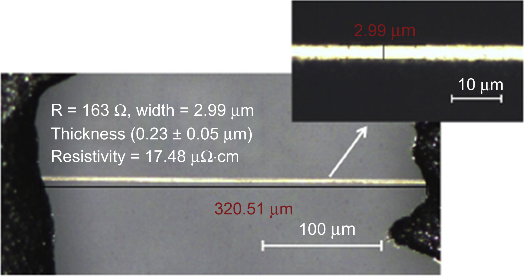
Figure 16.27 High-resolution silver line printing result patterned by electrohydrodynamic printing and laser sintering. From Son, S., Lee, S., Choi, J., 2014b. Fine metal line patterning on hydrophilic non-conductive substrates based on electrohydrodynamic printing and laser sintering. Journal of Electrostatics 72, 70–75. Copyright © 2013, Elsevier.

Figure 16.28 (a) AFM image and corresponding cross-sectional profile of the In2O3 channel on the source/drain electrodes. Scale bar, 10 μm. (b) Photograph (top, scale bar is 5 mm) and scanning electron microscope (SEM) image (bottom, scale bar is 250 μm) of In2O3 thin film transistor (TFT) array in a wavy configuration with electrohydrodynamic printing. The inset SEM image shows the TFT on the ridge of a wave. Scale bar, 250 μm. Modified from Kim, S.Y., Kim, K., Hwang, Y.H., Park, J., Jang, J., Nam, Y., Kang, Y., Kim, M., Park, H.J., Lee, Z., Choi, J., Kim, Y., Jeong, S., Bae, B.S., Park, J.U., 2016. High-resolution electrohydrodynamic inkjet printing of stretchable metal oxide semiconductor transistors with high performance. Nanoscale 8, 17113–17121. Copyright © 2016, Royal Society of Chemistry.
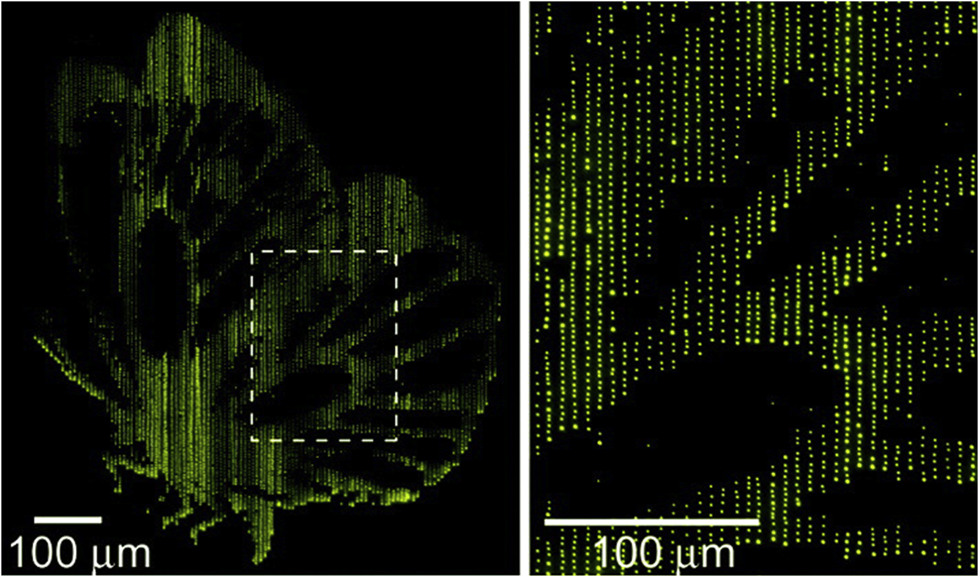
Figure 16.29 The images of patterns of DNA formed by e-jet printing based on electrohydrodynamic printing system. From Park, J., Lee, J.H., Paik, U., Lu, Y., Rogers, J.A., 2008. Nanoscale patterns of oligonucleotides formed by electrohydrodynamic jet printing with applications in biosensing and nanomaterials assembly. Nano Letters 8, 4210–4216. Copyright © 2008, American Chemical Society.
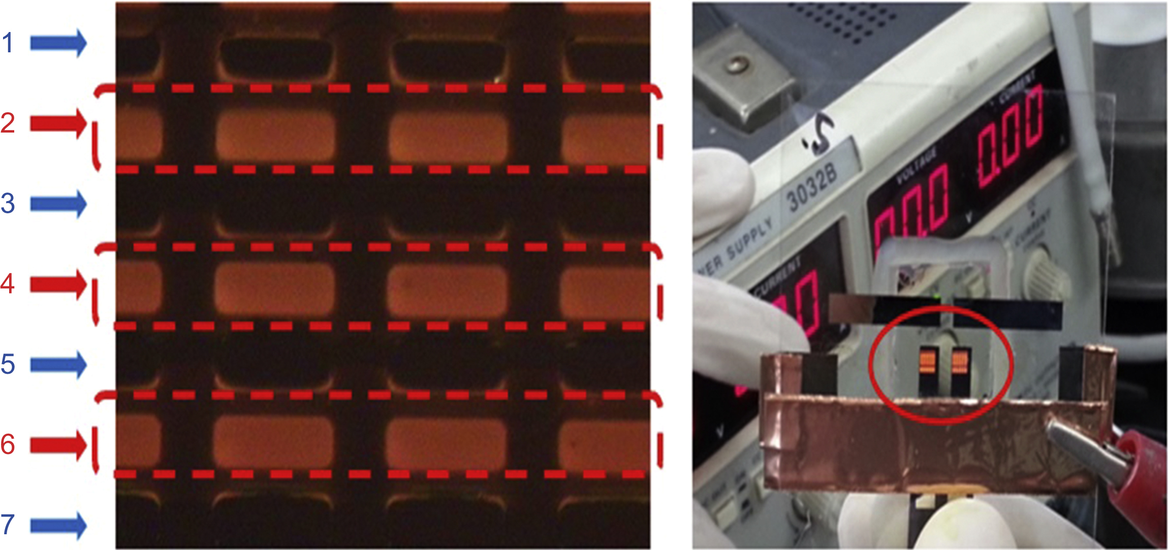
Figure 16.30 Electroluminescence image by selective electrohydrodynamic printing. Reproduced from Choi, J., Na, W., Son, S.U., Chae, H., Lee, S., Chung, H.K., 2013. High resolution OLED patterning using electrohydrodynamic printing. IMID 2013 Digest, the 13th International Metting on Information Display, 26–29 August 2013, Daegu, Republic of Korea, pp. 86.
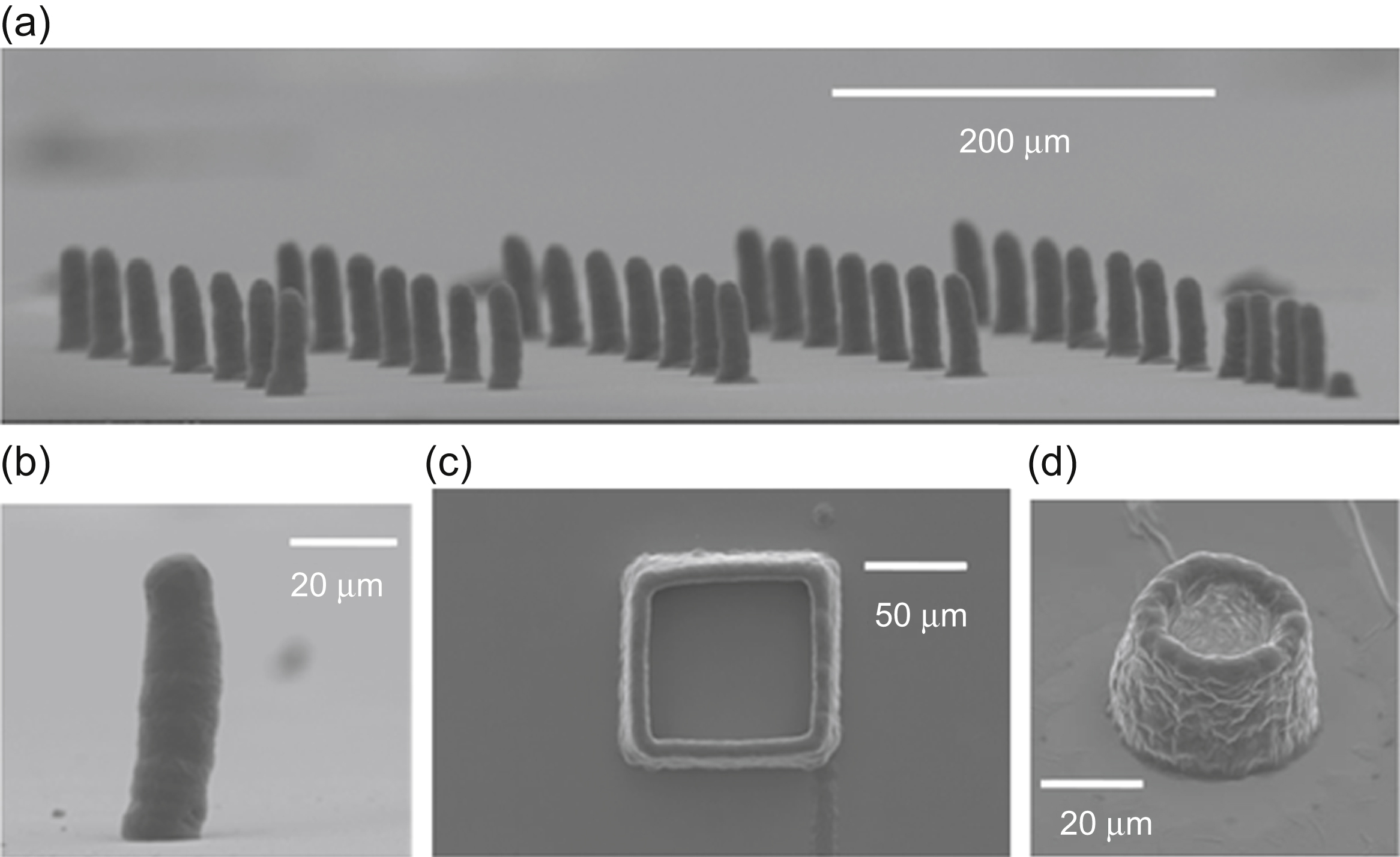
Figure 16.31 3D microstructures printed from electrohydrodynamic printing. (a) Micropillar array. (b) Close view of a single pillar. (c and d) Square and circular tube with thin walls. From Han, Y., Wei, C., Dong, J., 2014. Super-resolution electrohydrodynamic (EHD) 3D printing of micro-structures using phase-change inks. Manufacturing Letters 2, 96–99. Copyright © 2014, Elsevier.
16.5. Conclusion
Industrial applications of printing technology have recently attracted considerable attention as they offer a solution to simple and low-cost fabrication and advanced pattering processes in the manufacture of electronic devices. EHD printing technology, one of the printing technologies based on EHD theory, can offer high-resolution patterning and ejection of highly viscous ink to achieve thick patterns, unlike conventional inkjet printing systems—which are thermal-bubble and piezoelectric actuators. Therefore, an EHD print head based on the direct manipulation of the liquid by an electrical field appears more promising. The EHD spray phenomenon has different ejection modes depending on the initial electrical potential and ink properties. Among them, the microdripping, pulsed cone-jet and continuous cone-jet modes are suitable for the EHD print head. Thus, to control pattern resolution and thickness, the parameters for controlling of the pattern resolution and thickness of the EHD printing system are the nozzle/substrate (electrode) geometry, electrostatic field strength, ink properties, properties of the substrate surface, patterning repetition, and motor velocity.
Investigation was undertaken into the movements of the meniscus set up for the repeated ejection process to improve the structure and surface of the EHD printing nozzle. Also, the effects of various pulse voltages, frequencies, duty cycle, and pressures for meniscus deformation and ejection were explored to find the optimal region in EHD DOD printing for ensuring repeatability and stability. The research undertaken into the EHD printing system has shown it to be an attractive candidate for fine-patterned industrial applications.
..................Content has been hidden....................
You can't read the all page of ebook, please click here login for view all page.