
13
Microreaction chambers
Abstract
In this chapter, we present microsystems aimed to the chemical or biological synthesis of new products. The reaction typically happens in chambers inside the microsystem, where controlled conditions are in place, but other components are necessary to bring the samples to the chamber, precondition them, and monitor the whole process. All these components will be described, with special emphasis in one application that is expected to be widely used in the near future: the creation of drugs for animal or human consumption, particularly those synthesized from radioactive elements, which are very commonly used in tumor detection and diagnosis using positron-emission tomography.
Keywords
Chambers; Lab-on-chip; Total analysis system
13.1. Introduction
Chemical reactor systems have been adopted for many years in chemistry research and industrial processes. Small-scale versions (of micrometer size) of such reactors can take advantage of the improvements in efficiency that appears at such scales, for example, reduced reaction times, increased surface-to-volume ratio, smaller amounts of reagents needed, or increased throughput thanks to parallel processing (Pennathur, 2008; Stone, 2009; Rensch et al., 2013).
One of the most promising applications of reaction chambers is the efficient and industrial creation of pharmaceutical drugs. In general, improvements in the efficiency of any drug for disease treatment or prevention are welcome, but in recent years great progress has been made in the microfluidic production of radiopharmacy tracers to be applied in positron-emission tomography (PET) or other medical imaging techniques for the early detection of tumors.
This chapter contains a general description of fluidics and microfluidics, with the scientific approaches taken to understand movements of fluids at the microscale and the techniques used in the design of microdevices for fluids. It will then describe the different components that a standard microfluidic analysis or synthesis system (called a lab-on-a-chip) has. Several examples of existing reaction chambers used in radiopharmacy and other applications will follow. The chapter ends with conclusions and forecasts for the described technologies and applications.
13.2. Basics of microfluidics
In almost all cases, samples and reagents that are intended to react to create products and by-products are in fluid form. Therefore, knowledge of microfluidics is necessary to design and operate microsystems with reaction chambers intended to perform analysis or synthesis of chemical compounds. Microfluidics is the study of fluid movement at the micrometer scale. Although most of the macroscopic fluid physics laws are still valid, there are differences in the behavior, which need to be considered. In microfluidics we deal with small amounts of fluids flowing through small channels but whose properties can still be considered continuous. Except in particular cases of gases, the distance between molecules is very small compared with the typical dimensions of the microsystem.
Commonly, fluid flows are categorized into laminar and turbulent flows. In laminar flows, different parts of the fluid flow in parallel-like sheets (hence its name). On the other hand, in turbulent flows, there are vortices that make impossible to conceptually separate different parts of the flow. There is one important dimensionless parameter, called Reynolds number, which measures the relative importance of inertial and viscous forces and that can be calculated as
where ρ is the fluid density, L is the characteristic dimension of the flow, v is the typical velocity, and μ is the viscosity of the fluid. Flows that have different parameters such as lengths, velocities, and viscosities but that share the same Reynolds number are known to be similar, an effect that is very often used to build small-scale models of large structures such as wind turbines, dams, or ships.
Reynolds number is also used to predict transition from laminar to turbulent flow. In a pipe or closed channel, flow is laminar when Re < 2000 approximately; it is in a transition state for 2000 < Re < 4000 and it is turbulent when Re > 4000. Turbulent flows are less predictable than laminar ones and can sometimes even be quite chaotic but present some advantages depending on the application, the most important of which is the mixing, which is much more efficient when turbulence is present.
Given the small dimensions typical of microsystems, Reynolds number for most fluids and flows never go higher than about 1000, which means that flows are almost always laminar. Efficient mixing is thus difficult to achieve at the microscale, and elaborate geometries need to be designed to improve it. Chemical reactions are greatly benefited by a good mixing, and the adequate choice of the design is of utmost importance when reaction chambers are going to be used.
The general mathematical description of the movement of a fluid is called Navier–Stokes equations, after Claude-Louis Navier and George Gabriel Stokes. They result from the application of Newton's laws of movement to fluid motion and are of course applicable to macroscopic and microscopic flows. They are a set of differential partial nonlinear equations that are notoriously difficult to solve in general but whose solutions are known for a few specific cases. In the following paragraphs, these equations will be presented and the standard simplifications in the microscale will be discussed.
For an incompressible flow with no heat generation, the momentum equation can be written as
where u is the velocity vector at each point, g is the force per unit volume, and p is the pressure. The expression D/Dt is called the material derivative and is given by
In Eq. (13.2), the first term represents the total acceleration of a fluid differential volume and the second one the sum of all forces acting on it. Nonlinearity of the equations can be noticed in Eq. (13.3).
In microfluidics there are a number of simplifications that can be made to Eq. (14.2):
- • Effect of gravity can be ignored, given the small dimensions. This means that the term ρ·g does not appear.
- • Convection can be neglected, as Reynolds number is usually small. This removes the second part of Eq. (13.3).
Additionally, we can focus on stationary regime, where there is no variation with time, thus removing first term of Eq. (13.3) as well.
With these simplifications, the momentum equation is as simple as
which is called Poisson equation.
For simple domains such as circular pipes, reservoirs, and other, Poisson equation can be solved and detailed expressions for u can be obtained. Usually, the important parameters are not the velocity or pressure at each point but the averaged ones. And it is typical to express flow rate (the amount of mass passing through a section per unit of time, calculated as the integral of density times velocity on that section) as a function of the pressure difference between both ends of a pipe.
For example, for a channel with rectangular section with width w, height b, and length L, a good approximation when b/w > 0.7 is

where Q is the flow rate and Δp is the pressure difference in the channel. The ratio between pressure difference and flow rate is called the hydrodynamic resistance of the channel. It can be calculated for channels with other sections as well.
It turns out that fluidic movement fulfills the fact that at a given point
and in a closed loop
These expressions are identical to those of Kirchhoff laws, if we consider flow rate as corresponding to electrical current and pressure difference to voltage difference. This fact has led to the establishment of a full correspondence between fluidics and electronics, which applies under certain conditions (Perdigones et al., 2014).
Using this correspondence has the advantage of reutilizing the wide knowledge available on electrical and electronic circuits. It has been found that a microchannel with elastic walls is analogous to an electrical inductance, and a chamber with a membrane is analogous to an electrical capacitor. Microfluidics analogies of diodes, variable resistors, and even transistors do also exist (Mescher et al., 2009; Leslie et al., 2009; Takao et al., 2002; Perdigones et al., 2011). These equivalent devices have been used to design micropumps, pressure amplifiers, or digital microfluidic gates, among others (Cheow et al., 2007; Thorsen et al., 2002).
Often, the linearization of Navier–Stokes equations cannot be made because of the nature of the problem, and the movement is too complex to be solved analytically. A number of numerical methods, including finite elements method and volume of fluid method, are able to provide solutions to most microfluidic problems, although sometimes at a very high computational cost. Free software, such as simFlow, Flowsquare, SU2, and SimScale, and commercial products, such as COMSOL Multiphysics, Fluent, and ANSYS, are available (Zimmerman, 2006; Hirt and Nichols, 1981).
13.3. Components of a microfluidic system
As mentioned previously, the prototypical device in microfluidics is the lab-on-chip, sometimes also called micro–total analysis systems or point-of-care diagnosis systems. The aim is to be able to create such systems in a manner that they are cheap enough to be easily deployed to final users and disposed after use (Aracil et al., 2015; Pittet et al., 2008). To design and fabricate such a device, the reaction chamber, where the chemical or biological process happens, is the most important component, but other parts are also needed for the complete system to work. The fluidic samples that come from the outside or reservoirs are typically subjected to a pretreatment (mixing, heating, separating, etc.) before reaching the reaction chamber. After the reaction has taken place the results are measured using integrated or external sensors (optical, thermal, chemical, etc.) before disposing the waste. Of course, all these elements need external power that makes electronic components work and fluid samples to move inside the system from one component to the next one. This movement needs to be done in a controlled way so that the complete process takes place in a predictable way.
The rest of this section will describe the auxiliary components mentioned above.
13.3.1. Impulsion systems
Impulsion systems must take care of providing movement to the fluid samples, by supplying enough energy to make them flow in a controlled manner.
Peristaltic pumps are among the most common used ones in microfluidics. They consist on a movable membrane that compresses and expands a chamber, in a way similar to how the heart pumps blood. Similarly, to the heart as well, one-way valves are needed at the entrance and exit to ensure that flow has one direction. When the membrane deflects increasing the chamber volume, it is filled with fluid and allowed to enter through the entrance valve. After that, membrane deflects in the opposite way, compressing the chamber and expelling the fluid. The entrance valve does not allow the fluid going backward, while the exit one permits the fluid to go in the right direction. This last valve will also avoid fluid reentering the chamber in the next cycle. Many variations of this design have been built for microfluidics applications (Jeong and Yang, 2000; Ni et al., 2010).
Continuous micropumps also exist, for example, using electrical or magnetic fields. It is not uncommon to use magnetic fluids (by their own nature or by adding magnetic particles inside). They can be propelled using an external coil that creates a magnetic field (Kim et al., 2006).
For polar liquids such as water, electroosmotic pumps can be used. A small electrical charge is induced in the water layer next to the walls and then an electrical field is created in the direction of the flow. This is very efficient in terms of simplicity, although the achieved flow rates are typically small (Zeng et al., 2001).
Pumps based on rotating parts also exist, but they are quite complex to integrate in typical lab-on-chip devices (Shen et al., 2011).
13.3.2. Control
Active or passive valves control the flow of samples and reagent through the different steps. Passive valves are able to control fluid movement in a limited way, for example, by allowing flow in one direction through a channel but not in the other one as described above On the other hand, active valves need to be actuated externally using a smart control strategy that typically makes use of sensors to have feedback (Schumacher et al., 2012). Actuation of these valves is very often performed by electrical means, for example, by having a current flow through a copper line and then heating a chamber filled with air that expands and deflects a flexible membrane, which closes a microfluidic channel. Sometimes the deformation of such a membrane is directly performed by using pressurized air coming from an external source, making the valve actuation purely pneumatic instead of electrothermal.
13.3.3. Pretreatment
Pretreatment of the samples includes filtering, heating, mixing, and separating. As mentioned above, mixing presents challenges in microfluidic circuits because of the laminar flow. Typically, serpentine-shaped channels are placed, where fluids flow together. The serpentine shape serves the purpose of adding some turbulence for improving mixing and also of placing a long flow path in a reduced bidimensional space. Heating is usually performed by placing electrical resistors next to the channels or chambers. Separating components (Medoro et al., 2002) can be done by electromagnetic fields, decantation, or centrifugal pumping, among other methods.
The objective of microfluidic mixing is to carry out a rapid and effective mixing of the samples. A good mixing will help in the efficiency of the subsequent reactions. Microfluidic mixing processes can be considered as active, where an external energy force is applied to agitate the fluid, or passive, where the contact area and the contact time of the liquids are increased through microchannel configurations (Lee et al., 2011).
13.3.3.1. Active microfluidic mixers
Active mixers can use acoustic, dielectrophoretic, electrokinetic time pulse, pressure perturbation, electrohydrodynamic, magnetic, or thermal techniques to obtain the mixing.
In the acoustic actuation, some authors have studied the use of ultrasonic streams to obtain the mixing (Liu et al., 2003). In this device, a piezoelectric disk is used to move air bubbles in the microchamber at a frequency of 5 kHz. The mixing time is 6 s for a 40 V peak-to-peak excitation (Fig. 13.11).
The magnetohydrodynamic flow effect is used by some authors to fabricate micromixers (Bau et al., 2001). This micromixer is used with either DC or AC electrical and magnetic fields to generate Lorentz forces. These forces induce magnetohydrodynamic flows in a solution and mixing the fluid into the chamber.
13.3.3.2. Passive microfluidic mixers
Passive micromixers do not need moving parts or energy input to obtain the mixing. Passive mixers can use lamination, intersecting channels, zigzag channels, 3D serpentine channels, embedded barriers, and others for enhanced mixing.
Micromixers with intersecting channels are described in He et al. (2001). The authors explain the effect of a picoliter-volume mixer with intersecting channels of various lengths and a bimodal width distribution. In the design, all of the channels are parallel to the flow direction with a width of 5 μm (Fig. 13.12).
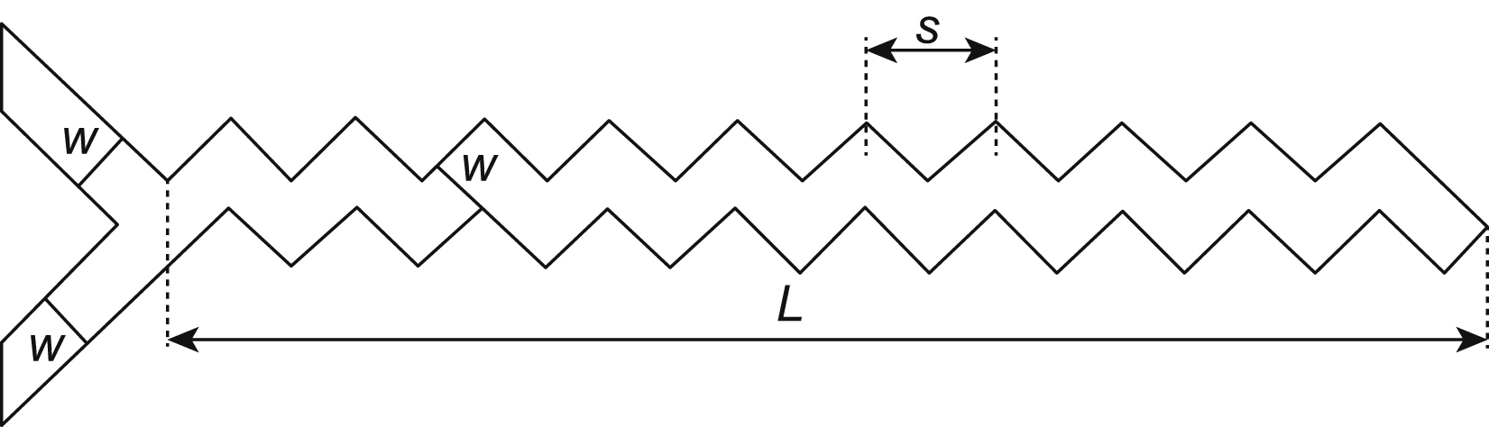
The effect of the mixing efficiency was investigated in many tests in the zigzag microchannel (Mengeaud et al., 2002). The results show that for Re = 0.26, the mixing efficiency increased from 65% to 83.8% as the geometry ratio s/w was augmented from 1 to 8, where w is the channel width and s the linear length of the periodic step (Fig. 13.13).
13.3.4. Measurement and sensing
One last step of sensing is almost always necessary to verify that the created products are the expected and to correct possible anomalies. Integration of pH, radioactive, gas, and flow or pressure sensors are routinely done in the lab-on-chip devices. Those based on fiber optics are among the most common ones (Ghafar-Zadeh and Sawan, 2007; Eaton and Smith, 1997; Kuswandi et al., 2007).
13.4. Reaction chambers
Generally, microfluidic reactor chambers are divided into two groups (Pascali et al., 2013): microvessel systems and microchannel systems.
Microvessel systems basically are a translation of devices used in macroscopic chemistry to smaller dimensions. In this way, the dimension of channels is typically in the range from nL to μL.
Microchannel systems could be defined as devices that are made up of channels with a maximum width of 300 μm. An important feature of these devices is the performance of the flow, which can sometimes change from laminar to turbulent. Systems with diameters greater than 300 μm are known as flow reactors. These are typically used in industrial production.
In this section, several examples and technological approaches to the fabrication of these and other small microfluidic reactors will be explained.
13.4.1. Example: ring-shaped reactor
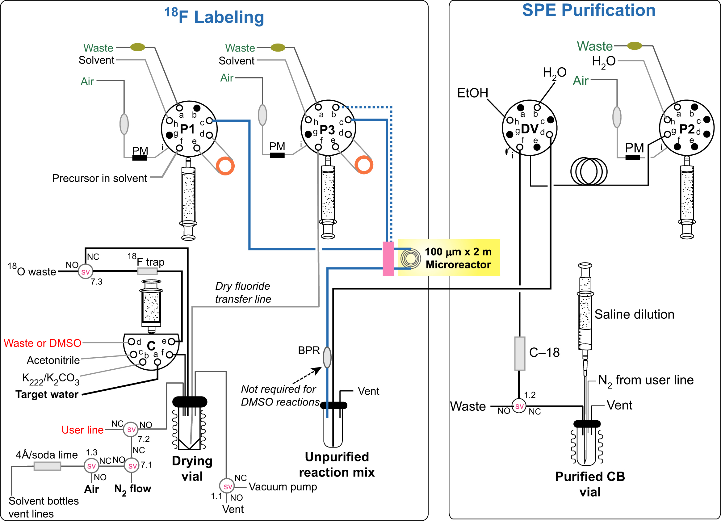
This device consists in a microvessel ring-shaped reactor for the radiosynthesis of [18F]FDG on one chip (Elizarov et al., 2006). This type of reactor is based on continuous flow and has been used to realize chemical radioactive synthesis on nanoliter to microliter scales. In this chemical reaction circuit all the process takes place in the same polydimethylsiloxane (PDMS) chip, reducing the exposure to contaminant radioactive agents and removing the need of transferring intermediates. In this integrated microfluidic device, five processes are performed: fluoride concentration, water evaporation, radiofluorination, solvent exchange, and hydrolytic deprotection.
The ring-shaped reactor has other advantages coming from the high concentration of fluoride. For that reason, increasing its concentration produces an increase in reaction times (Fig. 13.1). Because of microvessel design, in the chemical reactor circuit, the fluoride ion is diluted in a small volume of water and this volume of aqueous solution can be evaporated very fast. Therefore, in this system, no supplementary evaporations are necessary; this eliminates extra heating of some compounds that could produce its decomposition. Consequently, the advantages of these devices include higher heat transfer, faster diffusion times and reaction kinetics, and a better reaction product selectivity. The device accelerates the process and reduces the quantity of reagents and solvents required. It is designed to produce sufficient quantities of [18F]FDG (100–200 mCi) for mouse imaging.
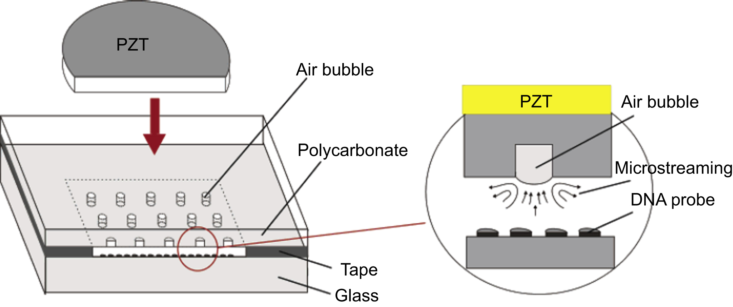
Figure 13.1 Ultrasonic mixer with PZT (lead zirconate titanate) piezoelectric disk used to move air bubbles in the microchamber.
13.4.1.1. Fabrication
The chip is fabricated using multilayer lithography. Two molds were fabricated to create the microfluidic channels and the control channel for actuating in the PDMS valves. The PDMS microfluidic channels of the device have a height of 45 μm and width of 200 μm. The control channel layer has a height of 25 μm and the width was set at 250 μm in the sectors where the valves are located.
13.4.1.2. Control interface
About the control interface, the pneumatic control consists of four sets of eight-channel manifolds regulated by a controller board. When a channel on the manifold is activated, argon gas enters the control interface connected to a valve channel, providing pressure to close valves in the microfluidic system. A Labview program allows manual control of each pneumatic valve and the automatization of the synthesis process.
13.4.1.3. Mixing
In the reaction phase, the dried potassium fluoride for radiosynthesis process is introduced into the reaction loop. After all the valves around the ring-shaped reaction loop are closed, the circuit is heated at 100°C for 30 s and maintained at 120°C for 50 s. The circuit is heated to remove the water residue inside the loop because the fluorination of the mannose triflate precursor requires anhydrous conditions. Meanwhile, the circulating pump was turned on to provide efficient mixing.
To sum up, the inhomogeneous solution is energetically mixed in the reaction loop by means of circulating pump and heated on a controlled hotplate.
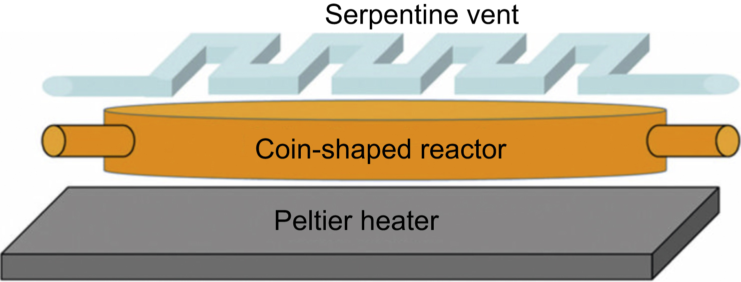
13.4.2. Example: coin-shaped reactor
This device also consists in a microfluidic reactor for Fludeoxyglucose (18F) (FDG) radiosynthesis (Elizarov et al., 2010). This reactor is the first one reported that has allowed batch-mode microfluidics systems to produce radiopharmaceuticals. It is able to synthetize human doses of 18F-FDG for PET.
PET utilizes biomarkers integrating isotopes, typically as 18F. These types of isotopes have a very short time of life. Therefore, it is essential to reduce the time of synthesis, purification, and deliver to the patient. The use of a microfluidic system can carry out synthetic step much more efficiently and is able to work near of the patient and the PET scanner. Furthermore, it is important in this kind of process that the device can be operated automatically without the interaction of a technician and minimizing the exposure to high radiation.
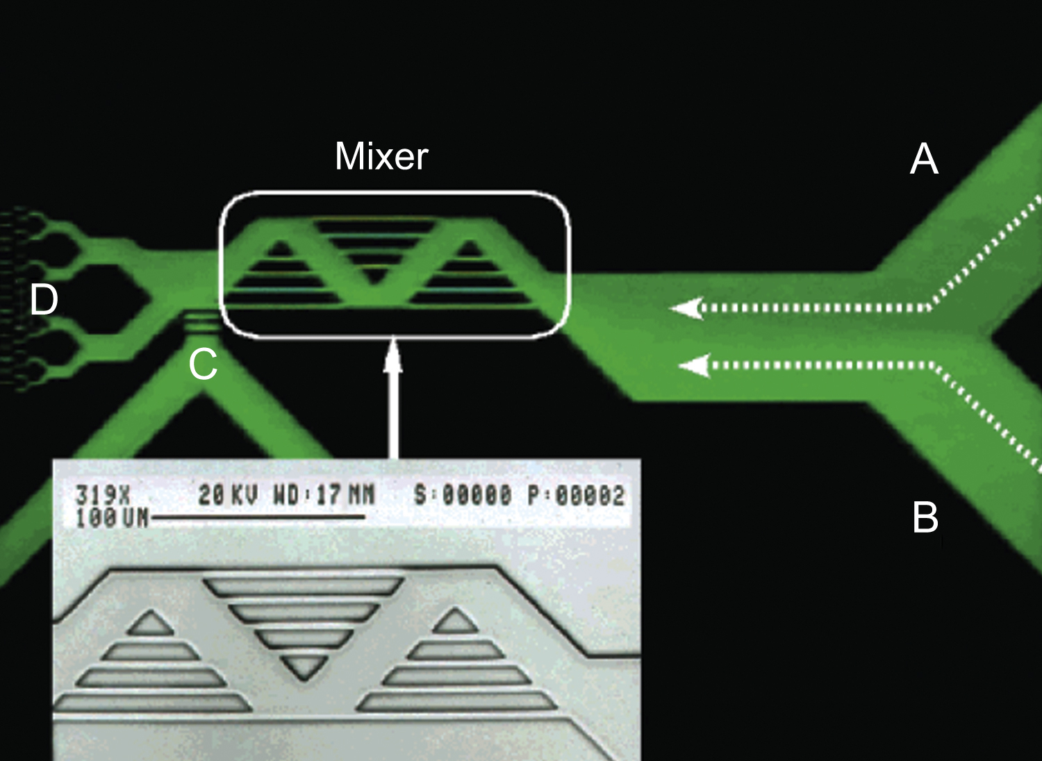
Figure 13.2 Photograph of picoliter-volume mixer with intersecting channels. Effect of mixing is evaluated by bringing in two fluids from channels A and B, and flowing to D. Channel C is not used.
The complete chip is made of PDMS using the soft lithography method and with a pneumatic push-up valves system for controlling the liquids. Elasticity and gas permeability of PDMS are the most important properties for the election of this material. The reactor is consisted of two different layers: the first one containing the coin-shaped reactor and the channels and the second one that combines the control valves and the radiator vent placed under the reactor chamber (Fig. 13.2).
This reactor is designed with a fixed volume. A disk of 5 mm diameter and 250 μm height is designed to maximize the heat transfer (short height ensures rapid temperature homogeneity) and it also helps the rapid escape of gas through the radiator vent. The circular form permits an efficient product removal and mixing of the product. Thanks to its shape, it provides a long area for including many inlet and outlet channels. The flow channels are fabricated with 45 μm height and 200 μm wide (Fig. 13.3).
13.4.2.1. Serpentine vent
A very important feature of this design is the serpentine vent placed below the coin-shaped reactor. This vent channel is separated from the reactor by a gas-permeable membrane providing the escape of the gas out of the chamber while the product is retained. For this purpose, it is necessary the application of vacuum in the vent to allow the gas removal from the chamber. On the other hand, the application of vacuum in the serpentine increases the reaction rates and prevents dead volumes of liquids inside of the chamber. The chamber can deform when vacuum is activated and pulls the liquids in the reactor during the synthesis phase. The serpentine vent is fabricated with 100 μm height and 250 μm wide channels, the separation between this and the reactor is 50 μm.
13.4.2.2. Mixing process
About the mixing of the reaction, a complete study and numerical modeling of flow optimization in a batch microfluidic reactor has been reported by the author (Elizarov et al., 2011). Numerical solutions of Navier–Stokes equations for different geometries of the reactor are validated using fluorescence imaging analysis techniques.
In the radiosynthesis of PET tracers, it is critical for the reagents being meticulously and quickly mixed for obtaining a suitable product. In this way, a very significant requirement for this synthesis chips is that their reagents must be eluted efficiently to pass the quality control. With this purpose, the effect of the angle and the flow rate of the eluent inside of the chamber are being investigated enabling the optimization of operation parameters and geometry (Fig. 13.4).
The numerical study is modeled with COMSOL Multiphysics and covers two essential characteristics of the flow. The first one is the angle the liquid entering in the reactor and its influence in the mixing. The second one is the effect of the inlet pressure. Finally, as it is said before, the improvement in the mixing process increases the efficiency of the elution.
Proves have been made with multiple entries and with single entry. The six inlet layouts have been evaluated by basing on the idea that multiple fluid entry could increase the mixing. In fact, with this mixing the liquid inertia is reduced as a single inlet flow split between the six inlets and this decreases the efficiency of the sample. This is the reason why the author uses a single inlet in his simulations.
Regarding the effect of the serpentine vent in the mixing, its main function is to eliminate gases through the membrane by applying negative pressure to the vent line. The increase of the pressure gradient produces an increase of the velocity of liquid entry and improves the mixing in the chamber. This “vacuum-assisted” technique led to substantial improvement of mixing at 0,7-1 bar inlet pressure.
Finally, the author studies the efficiency of elution using florescent imaging. Two geometries are selected for proves. One geometry has inlet and outlet channels opposite each other and the other geometry utilizes a tangential inlet and outlet. In the test, the tangential channels are always more efficient than the perpendicular ones. Several flow rates and input and output angles have been tested. Therefore, a tangential elution at α = 45 degrees and β = 60 degrees (where α is the input angle and β the output angle) supposes the best configuration for reducing times and improving elution, as well as a flow rate of q = 15 μL/s.
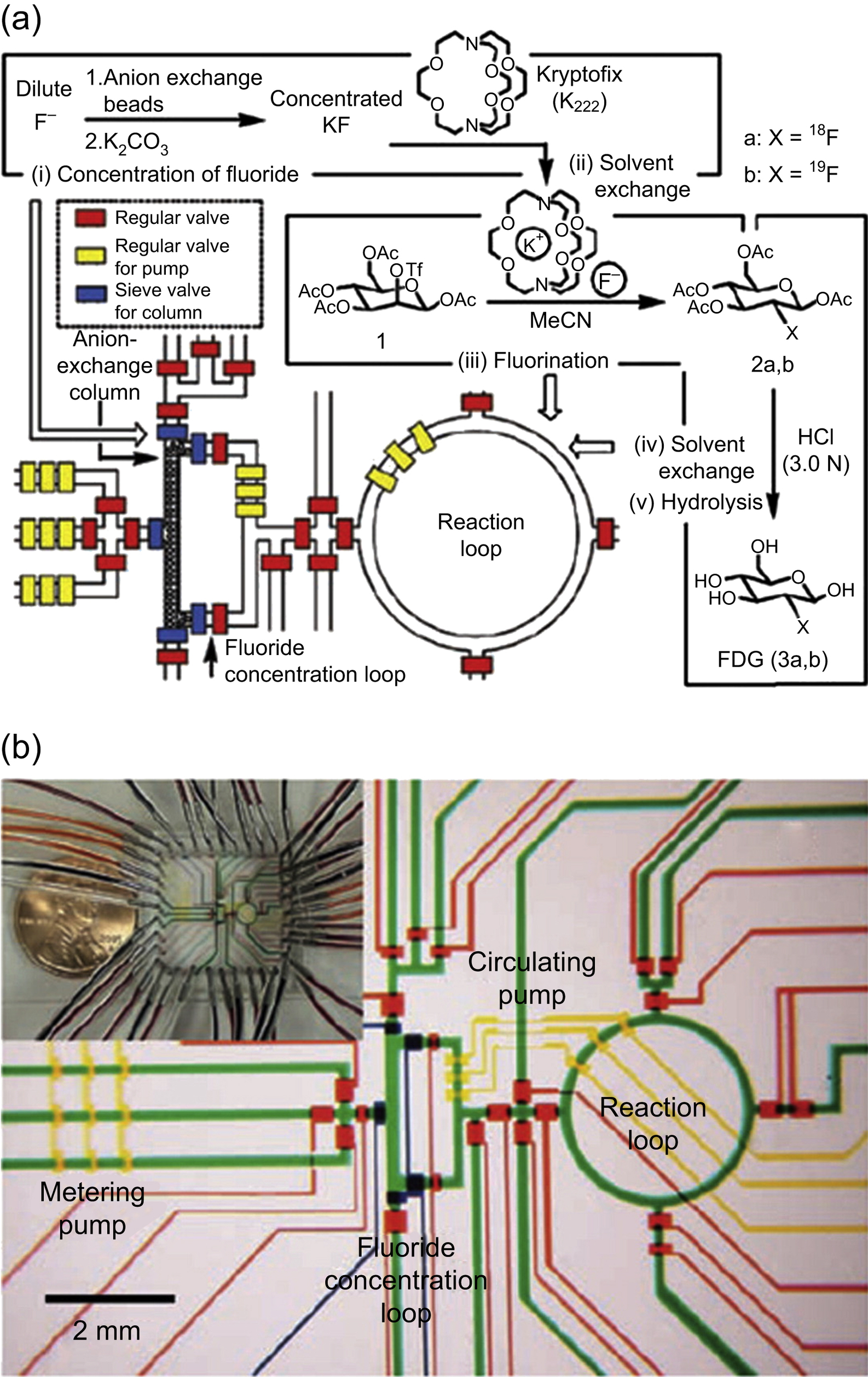
Figure 13.4 (a) Schematic representation of a chemical reaction circuit used in the production of FDG. (b) Representation of the central area of the microfluidic circuit.
13.4.3. Example case: NanoTek
An example of microchannel system is the NanoTek developed by Advion (USA, product code: 900-0003). In fact, the NanoTek Microfluidic Chemistry System is able to offer the microscale and macroscale synthesis by using many isotopes (Pascali et al., 2010). The modular components of this platform provide flexibility in tracers' production. The synthesis process is normally completed in 1–2 min and the system allows to accept multiple syntheses in 1 day with one delivery of activity and using μg of reagent.
The system consists in one concentration module and one base module and controlled by a software. The concentration module includes a low-pressure syringe pump connected to a six-way valve and a thermostated housing. This module is used to prepare the dry fluoride compound with an anion-exchange resin trapping. The base module has two blocks: the reactor module and the pump module. The pump module is made up of two syringe pumps connected to an eight-way valve (Fig. 13.5).
13.4.3.1. Reactor module
The most important part is the reactor module, which is composed by a third syringe pump connected to another eight-way valve and four thermostated slots, where the microreactors are hosted. The microreactor is made of silica tubing (110 μm ID; length: 2 m) rolled and hold by a brass ring.
This process is executed on the concentration module. After bombardment, the fluoride water coming from the cyclotron is passed through the preconditioned column. The fluoride is eluted into the reactor preheated to 110°C. Nitrogen flow and vacuum are applied to the reactor while delivering the fluoride solution to facilitate solvent evaporation. The solution is evaporated to dryness.
13.4.3.2. Characteristics
Therefore, the main features of the microscale concentrator and evaporator module are given by the following:
- • Evaporates volumes up to 2 mL.
- • Accurately transfers volumes as small as 100 μL.
- • Rapidly heats and cools chamber.
- • Can be used for concentrating, purification, or batch chemical reactions.
- • Pump module for dispensing additional reagents.
- • Reactor module enabling multiple reaction steps.
- • Four-stage cartridge with plug-in reactors.
- • Solvent-tolerant wetted parts.
- • High-pressure loop and distribution valve.
13.4.4. Other microreactors
Although one of the most interesting applications for microreactors is synthesis of 18F-FDG and chemical synthesis, there are many other types of reactors for different uses.
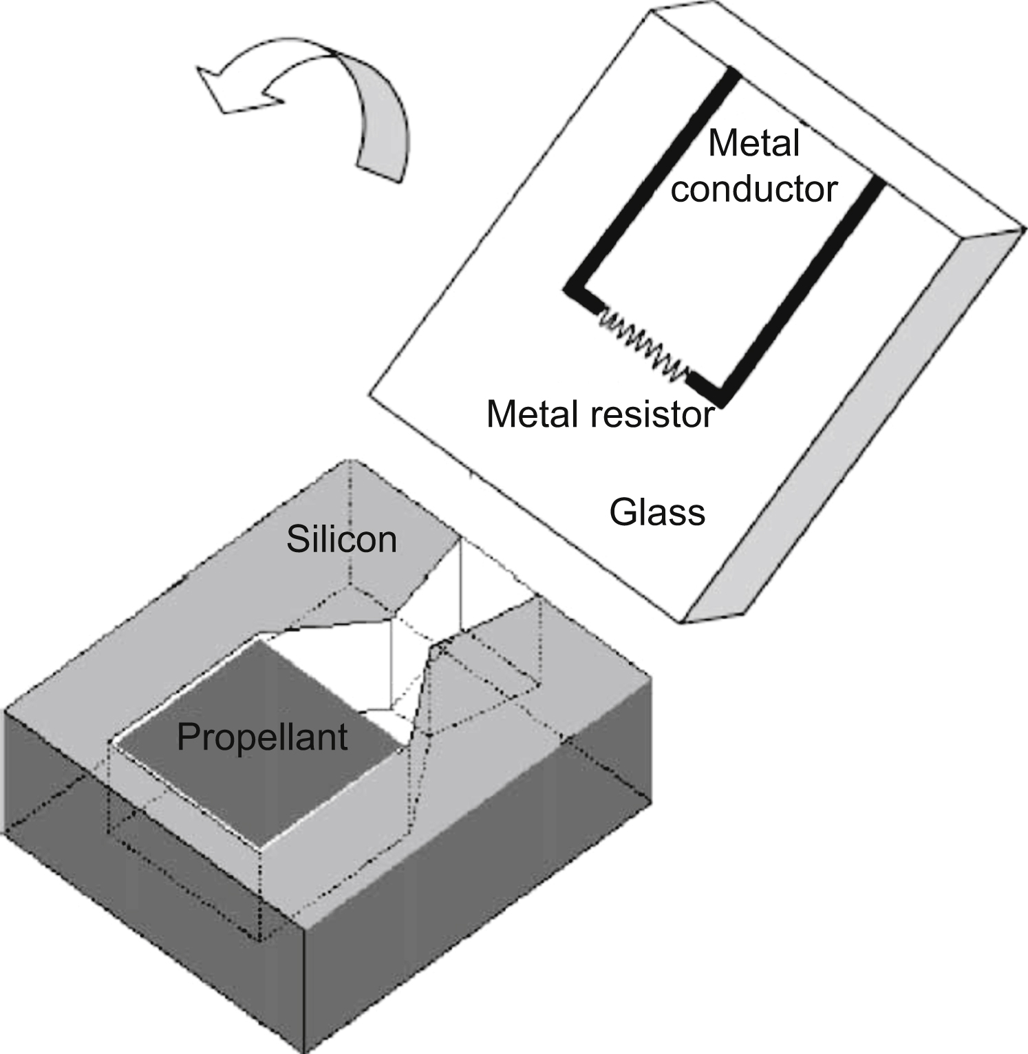
13.4.4.1. Microthrusters
A very curious application for microreactors is like a microthruster (Zhang et al., 2005). A microthruster with Au/Ti igniter is utilized as a micropropulsion system for microspacecraft. In this work, a single microthruster and microthruster arrays have been fabricated using standard microfabrication technologies.
The fabrication of a single microthruster starts with the deposition of a metal igniter in a sodium-rich glass wafer by lift-off method. Then, a silicon wafer is fabricated using microfabrication technologies to contain a combustion chamber. The glass layer and the silicon layer are bonded together to form the microthruster. Finally, the chamber is loaded with the propellant (Fig. 13.6).

Once it is ignited, the resultant gas expands through the chamber as its velocity increases drastically, producing the desired impulse. The combustion in the microchamber is observed through the transparent glass layer. The tests produced 2.11 × 10⁻⁵ to 1.15 × 10⁻⁴ N of total impulse at sea level and 3.52 × 10⁻⁵ to 2.22 × 10⁻⁴ N of total impulse in vacuum.
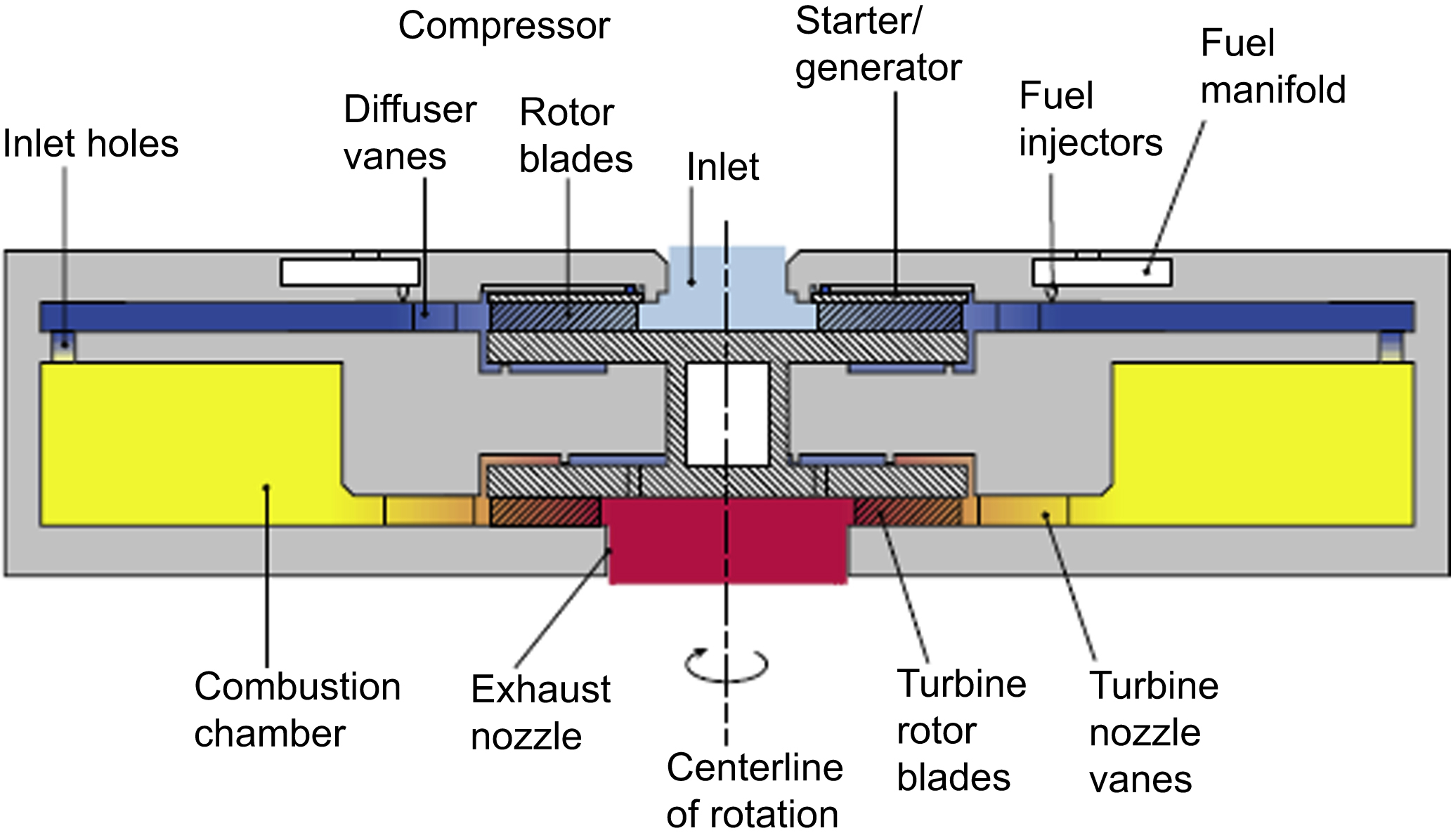
13.4.4.2. Microturbines
The microturbine-based generator systems are considered a feasible form of energy source. Generally, the microturbine provides input mechanical energy, which is converted to electrical signal by a generator.
An example of these types of devices is the hydrogen combustor for a microfabricated gas turbine engine (Mehra and Waitz, 1998). The device consists of three silicon wafers housing a fuel manifold and injectors, a combustion inlets holes, and a combustion chamber. The reactor chamber is a circular region with 66 mm2 of volume and 1 mm of height, providing exit temperatures of up to 1800K. The fuel injector forms are design for a suitable jet injection and mixing (Fig. 13.7).
13.4.5. Heating methods
On the thermal energy transfer, the reactor must enable rapid heat transfer to the components. Precise and rapid heating of low reaction volumes is a significant advantage of microfluidics in this field and has demonstrated to improve synthesis time and yield on some PET tracer syntheses.
13.4.5.1. Resistors
Heating can be carried out via resistive heaters or radiator heating. In this way, the geometric optimization of the microheaters is significant. Some authors provide simulated results of microheaters having an improved temperature distribution and higher density of integration (Velmathi et al., 2010). The microheaters must be designed to ensure low power consumption, low thermal mass, and better temperature uniformity.
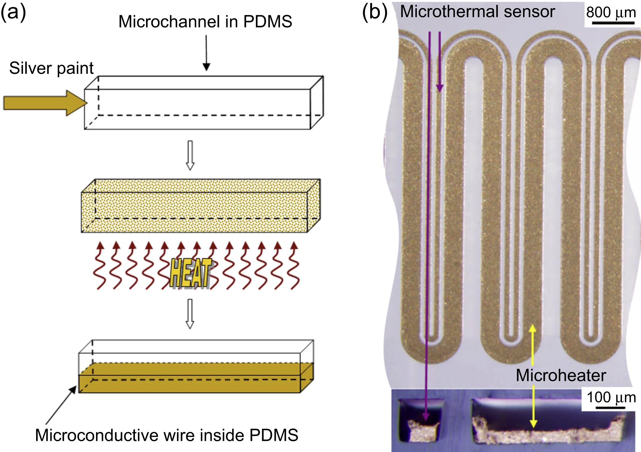
PDMS is widely used in microfluidic applications. For this reason, it is interesting the integration of heaters in the PDMS chip. For instance, a possibility is the fabrication of a microheater and a thermal sensor placed inside elastomeric PDMS microchannels by injecting silver paint or other conductive materials (Wu et al., 2009). To make this device, after the microchannels are fabricated, the silver paint is injected into the channel. Then, the chip is heated to evaporate the solvent of silver paint and the residual silver particles subsequently are heated to form conductive wires. The microwires are used as a heater and as a thermal sensor. The narrow wire serves as a temperature sensor because its resistance is variable with temperature, while the wider one is used as the microheater (Fig. 13.8).

Figure 13.7 Mixing process in coin-shaped reactor: (a) Fluride filling, (b) reactor contraction by vacuum application, (c) triflate filling-manifold, (d) triflate filling/mixing by reactor expansion followed by fluoration, (e) partial MeCN evaporation (65ºC), (f) reactor contraction by vacuum application, (g) HCl filling/chemically-assisted mixing, (h) hydrolysis/MeCN evaporation (75ºC), (i) product elution.
13.4.5.2. Microwave
Microwave radiochemical syntheses have been reported for over two decades. The principal advantage of the use of microwave heating is to reduce reaction times during the process. In addition, this is an advantage in labeling with short-lived radionuclides. However, this technique has found limited application to microfluidic chemistry, mainly because of hardware and macro-to-micro interface integration.
There are some articles about microreactors heated by microwaves. For example, a microfluidic reactor heated by microwave irradiation can be utilized to prepare LaF3/LaPO4:Ce,Tb nanocrystals using ethylene glycol as solvent (Zhu et al., 2010). The microwave effect combined with the microfluidic reactor accelerates the nucleation stage and stimulates the growth stage of nanocrystals, which produces better luminescent properties (Fig. 13.9).
13.4.5.3. Peltier
As it was mentioned before, rapid heating of low volumes is a significant advantage. On the other hand, rapid and effective cooling may also be desired for many applications. In this sense, Peltier cells could be a good solution for some devices. As it is known, the Peltier effect is the presence of heating or cooling at an electrified junction of two different conductors.

Peltier cells are frequently used in microfluidics as heaters (Yang et al., 2002). In this study, a serpentine-shaped (0.75 mm) polycarbonate plastic polymerase chain reaction microreactor has been constructed and tested. This chip is used for the detection of Escherichia coli K12-specific gene fragment. The device was designed and built in-house using two Peltier thermoelectric devices (output power of 18.1 W). The microfluidic device was sandwiched between the two Peltier elements (Fig. 13.10).
13.5. Conclusions
Developments in microdevices aimed to chemically or biologically create new products in fluid form can lead to drastic advances in efficiency and profitability. In particular, the ability of synthesizing drugs at request of the doctors and close to the patient has enormous advantages in many aspects of the pharmaceutical industry, of which the creation of injectable radiopharmacy doses for PET imaging and diagnosis is the most prominent example.
The microchambers and related devices described here are not limited to drug production, but they can also be used in other phases, such as sample preparation, synthesis of samples, preclinical automated testing, etc. It is only expected that microfluidics use in pharmacy and related industries will significantly increase in the coming years.
..................Content has been hidden....................
You can't read the all page of ebook, please click here login for view all page.