
11
Understanding the Different Domains in Software Solutions
This chapter is dedicated to a modern software development technique called domain-driven design (DDD), which was first proposed by Eric Evans. While DDD has existed for more than 15 years, it has achieved great success in the last few years because of its ability to cope with two important problems.
The main problem is modeling complex systems that involve several domains of knowledge. No single expert has in-depth knowledge of the whole domain; this knowledge is instead split among several people. Moreover, each expert speaks a language that is specific to their domain of expertise, so for effective communication between the experts and the development team objects, interfaces and methods must mimic the language of the domain experts. This means that the different modules that compose an application must use a different vocabulary for each domain of expertise. Consequently, the application must be split into modules that reflect the different domains of knowledge, and the interface between modules that deals with the different domains of knowledge must be carefully designed to carry out the necessary translations.
DDD copes with this problem by splitting the whole CI/CD cycle into independent parts, assigned to different teams. This way, each team can focus on a specific domain of knowledge by interacting only with the experts of that domain.
That’s why the evolution of DDD is interleaved with the evolution of microservices and DevOps. Thanks to DDD, big projects can be split among several development teams, with each team having a different domain of knowledge. There are many reasons why a project is split among several teams, the most common being the team’s size and all of its members having different skills and/or different locations. In fact, experience has proven that teams of more than 6-8 people are not effective and, clearly, different skills and locations prevent tight interaction from occurring. Team splitting prevents tight interaction from happening for all the people involved in the project.
In turn, the importance of the two aforementioned problems has grown in the last few years. Software systems have always taken up a lot of space inside every organization, and they have become more and more complex and geographically distributed.
At the same time, the need for frequent updates has increased so that these complex software systems can be adapted to the needs of a quickly changing market.
These problems led to the conception of more sophisticated CI/CD cycles and the adoption of complex distributed architectures that may make use of reliability, high throughput, quick updates, and the capability to evolve legacy subsystems gradually. Yes—we are speaking of the microservices and container-based architectures we analyzed in Chapter 5, Applying a Microservice Architecture to Your Enterprise Application.
In this scenario, it’s common to implement complex software systems with associated fast CI/CD cycles that always require more people to evolve and maintain them. In turn, this created a need for technologies that were adequate for high-complexity domains and for the cooperation of several loosely coupled development teams.
In this chapter, we will analyze the basic principles, advantages, and common patterns related to DDD, as well as how to use them in our solutions. More specifically, we will cover the following topics:
- What are software domains?
- Understanding DDD
- Using SOLID principles to map your domains
- Use case—understanding the domains of the use case
Let’s get started.
Technical requirements
This chapter requires Visual Studio 2022 free Community Edition or better with all the database tools installed.
All the code snippets in this chapter can be found in the GitHub repository associated with this book, https://github.com/PacktPublishing/Software-Architecture-with-C-10-and-.NET-6-3E.
What are software domains?
As we discussed in Chapter 2, Non-Functional Requirements, and Chapter 3, Documenting Requirements with Azure DevOps, the transfer of knowledge from domain experts to the development team plays a fundamental role in software design. Developers try to communicate with experts and describe their solutions in a language that domain experts and stakeholders can understand. However, often, the same word has a different meaning in various parts of an organization, and what appear to be the same conceptual entities have completely different shapes in different contexts.
For instance, in our WWTravelClub use case, the order-payment and packages-handling subsystems use completely different models for customers. Order-payment characterizes a customer by their payment methods, currency, bank accounts, and credit cards, while packages-handling is more concerned with the locations and packages that have been visited and/or purchased in the past, the user’s preferences, and their geographical location. Moreover, while order-payment refers to various concepts with a language that we may roughly define as a bank language, packages-handling uses a language that is typical of travel agencies/operators.
The classic way to cope with these discrepancies is to use a unique abstract entity called customer, which projects into two different views—the order-payment view and the package-handling view. Each projection operation takes some operations and some properties from the customer abstract entity and changes their names. Since domain experts only give us the projected views, our main task as system designers is to create a conceptual model that can explain all the views. The following diagram shows how different views are handled:

Figure 11.1: Creating a unique model
The main advantage of the classic approach is that we have a unique and coherent representation of the data of the domain. If this conceptual model is built successfully, all the operations will have a formal definition and purpose and the whole abstraction will be a rationalization of the way the whole organization should work, possibly highlighting and correcting errors and simplifying some procedures.
However, what are the downsides of this approach?
The sharp adoption of a new monolithic data model may cause an acceptable impact in a small organization, when the software is destined for a small part of the overall organization, or when the software automatizes a small enough percentage of the data flow. However, if the software becomes the backbone of a complex geographically distributed organization, sharp changes become unacceptable and unfeasible. Complex structured companies require a gradual transition from the old organization to the new organization. In turn, a gradual transition is possible only if old data models can coexist with new data models, and if each of the various components of the organization is allowed to change at its own speed, that is, if each component of the organization can evolve independently of the others.
Moreover, as the complexity of the software system grows, several other issues appear, as follows:
- Coherency issues: Arriving at a uniquely coherent view of data becomes more difficult since we can’t retain the complexity when we break these tasks into smaller, loosely coupled tasks.
- Difficulties updating: As complexity grows, there is a need for frequent system changes, but it is quite difficult to update and maintain a unique global model. Moreover, bugs/errors that are introduced by changes in small subparts of the system may propagate to the whole organization through the uniquely shared model.
- Team organization issues: System modeling must be split among several teams, and only loosely-coupled tasks can be given to separate teams; if two tasks are strongly coupled, they need to be given to the same team.
- Parallelism issues: The need to move to a microservice-based architecture makes the bottleneck of a unique database more unacceptable.
- Language issues: As the system grows, we need to communicate with more domain experts, each speaking a different language and each with a different view of that data model. Thus, we need to translate our unique model’s properties and operations to/from more languages to be able to communicate with them.
As the system grows, it becomes more inefficient to deal with records with hundreds/thousands of fields. Such inefficiencies originate in database engines that inefficiently handle big records with several fields (memory fragmentation, problems with too many related indices, and so on). However, the main inefficiencies take place in object-relational mappings (ORMs) and business layers that are forced to handle these big records in their update operations. In fact, while query operations usually require just a few fields that have been retrieved from the storage engine, updates and business processing involve the whole entity.
As the traffic in the data storage subsystem grows, we need read and update/write parallelism in all the data operations. As we discussed in Chapter 8, How to Choose Your Data Storage in the Cloud, while read parallelism is easily achieved with data replication, write parallelism requires sharding, and it is difficult to shard a uniquely monolithic and tightly connected data model.
These issues are the reason for DDD’s success in the last few years because they were characterized by more complex software systems that became the backbones of entire organizations. DDD’s basic principles will be discussed in detail in the next section.
Understanding domain-driven design
According to DDD, we should not construct a unique Domain Model that keeps all the views as separate models. Instead, the whole application domain is split into smaller domains, each with a separate model. These separate domains are called Bounded Contexts. Each domain is characterized by the language used by the experts and used to name all the domain concepts and operations. Thus, each domain defines a common language used by both the experts and the development team called a Ubiquitous Language. Translations are not needed anymore, and if the development team uses C# interfaces as bases for its code, the domain expert is able to understand and validate them since all the operations and properties are expressed in the same language that’s used by the expert.
Here, we’re getting rid of a cumbersome unique abstract model, but now we have several separate models that we need to relate somehow. DDD proposes that it will handle all of these separate models, that is, all the Bounded Contexts, as follows:
- We need to add Bounded Context boundaries whenever the meanings of the language terms change. For instance, in the WWTravelClub use case, order-payment and packages-handling belong to different Bounded Contexts because they give a different meaning to the word customer.
- We need to explicitly represent relations among Bounded Contexts. Different development teams may work on different Bounded Contexts, but each team must have a clear picture of the relationship between the Bounded Context it is working on and all the other models. For this reason, such relationships are represented in a unique document that’s shared with every team.
- We need to keep all the Bounded Contexts aligned with CI. Meetings are organized and simplified system prototypes are built in order to verify that all the Bounded Contexts are evolving coherently, that is, that all the Bounded Contexts can be integrated into the desired application behavior.
The following diagram shows how the WWTravelClub example that we discussed in the previous section changes with the adoption of DDD:
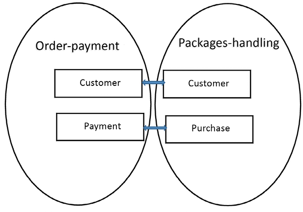
Figure 11.2: Relations between DDD Bounded Contexts
There is a relationship between the customer entities of each Bounded Context, while the purchase entity of the packages-handling Bounded Context is related to the payments. Identifying entities that map to each other in the various Bounded Contexts is the first step of formally defining the interfaces that represent all the possible communications among the contexts.
For instance, in the previous diagram, since payments are done after purchases, we can deduce that the order-payment Bounded Context must have an operation to create a payment for a specific customer. In this domain, new customers are created if they don’t already exist.
The payment creation operation is triggered immediately after purchase. Since several more operations are triggered after an item is purchased, we can implement all the communication related to a purchase event with the Publisher/Subscriber pattern we explained in Chapter 10, Design Patterns and .NET 6 Implementation. These are known as domain events in DDD. Using events to implement communications between Bounded Contexts is very common since it helps keep Bounded Contexts loosely coupled.
Once an instance of either an event or an operation that’s been defined in the Bounded Context’s interface crosses the context boundary, it is immediately translated into the Ubiquitous Language of the receiving context. It is important that this translation is performed before the input data starts interacting with the other domain entities to prevent the Ubiquitous Language of the other domain from becoming contaminated by extra-contextual terms.
Each Bounded Context implementation must contain a Data Model Layer completely expressed in terms of the Bounded Context Ubiquitous Language (class and interface names and property and method names), with no contamination from other Bounded Contexts’ Ubiquitous Languages, and without contamination from programming technical stuff. This is necessary to ensure good communication with domain experts and to ensure that domain rules are translated correctly into code so that they can be easily validated by domain experts.
When there is a strong mismatch between the communication language and the target Ubiquitous Language, an anti-corruption layer is added to the receiving Bounded Context boundary. The only purpose of this anti-corruption layer is to perform a language translation.
The document that contains a representation of all the Bounded Contexts, along with the Bounded Contexts’ mutual relationships and interface definitions, is called a Context Mapping. The relationships among contexts contain organizational constraints that specify the kind of cooperation that’s required among the team that works on the different Bounded Contexts. Such relationships don’t constrain the Bounded Context interfaces but do affect the way they may evolve during the software CI/CD cycle. They represent patterns of team cooperation. The most common patterns are as follows:
- Partner: This is the original pattern suggested by Eric Evans. The idea is that the two teams have a mutual dependency on each other for delivery. In other terms, they decide together and, if needed, change the Bounded Context’s mutual communication specifications during the software development lifecycle.
- Customer/supplier development teams: In this case, one team acts as a customer and another one acts as a supplier. Both teams define the interface of the customer side of the Bounded Context and some automated acceptance tests to validate it. After that, the supplier can work independently. This pattern works when the customer’s Bounded Context is the only active part that invokes the interface methods that are exposed by the other Bounded Context. This is adequate for the interaction between the order-payment and the packages-handling contexts, where order-payment acts as a supplier since its functions are subordinate to the needs of packages-handling. When this pattern can be applied, it decouples the two Bounded Contexts completely.
- Conformist: This is similar to the customer/supplier pattern, but in this case, the customer side accepts an interface that’s been imposed by the supplier side with no negotiation stage. This pattern offers no advantages to the other patterns, but sometimes we are forced into the situation depicted by the pattern since either the supplier’s Bounded Context is implemented in a preexisting product that can’t be configured/modified too much, or because it is a legacy subsystem that we don’t want to modify.
It is worth pointing out that the separation in Bounded Contexts is only effective if the resulting Bounded Contexts are loosely coupled; otherwise, the reduction of complexity that’s obtained by breaking a whole system into parts would be overwhelmed by the complexity of the coordination and communication processes.
However, if Bounded Contexts are defined with the language criterion, that is, Bounded Context boundaries are added whenever the Ubiquitous Language changes, this should actually be the case. In fact, different languages may arise as a result of a loose interaction between an organization’s subparts since the more each subpart has tight interactions inside of it and loose interactions with other subparts, the more each subpart ends up defining and using its own internal language, which differs from the language used by the other subparts.
Moreover, all human organizations can grow by evolving into loosely coupled subparts for the same reason complex software systems may be implemented as the cooperation of loosely coupled submodules: this is the only way humans are able to cope with complexity. From this, we can conclude that complex organizations/artificial systems can always be decomposed into loosely coupled subparts. We just need to understand how.
Beyond the basic principles we’ve mentioned so far, DDD provides a few basic primitives to describe each Bounded Context, as well as some implementation patterns. While Bounded Context primitives are an integral part of DDD, these patterns are useful heuristics we can use in our implementation, so their usage in some or all Bounded Contexts is not obligatory once we opt for DDD adoption.
In the next section, we will describe primitives and patterns.
Entities and value objects
DDD entities represent domain objects that have a well-defined identity, as well as all the operations that are defined on them. They don’t differ too much from the entities of other, more classical approaches. Also, DDD entities are the starting point of the storage layer design.
The main difference is that DDD stresses their object-oriented nature, while other approaches use them mainly as records whose properties can be written/updated without too many constraints. DDD, on the other hand, forces strong SOLID principles on them to ensure that only certain information is encapsulated inside of them and that only certain information is accessible from outside of them, to stipulate which operations are allowed on them, and to set which business-level validation criteria apply to them.
In other words, DDD entities are richer than the entities of record-based approaches.
In other approaches, operations that manipulate entities are defined outside of them in classes that represent business and/or domain operations. In DDD, these operations are moved to the entity definitions as their class methods. The reason for this is that they offer better modularity and keep related chunks of software in the same place so that they can be maintained and tested easily.
For the same reason, business validation rules are moved inside of DDD entities. DDD entity validation rules are business-level rules, so they must not be confused with database integrity rules or with user-input validation rules. They contribute to the way entities represent domain objects by encoding the constraints the represented objects must obey. In .NET, business validation can be carried out with one of the following techniques:
- Calling the validation methods in all the class methods that modify the entity
- Hooking the validation methods to all the property setters
- Decorating the class and/or its properties with custom validation attributes and then invoking the
TryValidateObjectstatic method of theSystem.ComponentModel.DataAnnotations.Validatorclass on the entity each time it is modified
Once detected, validation errors must be handled somehow; that is, the current operation must be aborted and the error must be reported to an appropriate error handler. The simplest way to handle validation errors is by throwing an exception. This way, both purposes are easily achieved and we can choose where to intercept and handle them. Unfortunately, as we discussed in the Performance issues that need to be considered while programming in C# section of Chapter 2, Non-Functional Requirements, exceptions imply big performance penalties, and must be used to deal just with “exceptional circumstances” so, often, different options are considered. Handling errors in the normal flow of control would break modularity by spreading the code that’s needed to handle the error all over the stack of methods that caused the error, with a never-ending set of conditions all over that code. Therefore, more sophisticated options are needed.
A good alternative to exceptions is to notify errors to an error handler that is defined in the dependency injection engine. Being scoped, the same service instance is returned while each request is being processed so that the handler that controls the execution of the whole call stack can inspect possible errors when the flow of control returns to it and can handle them appropriately. Unfortunately, this sophisticated technique can’t abort the operation’s execution immediately or return it to the controlling handler.
This is why often exceptions are used for this scenario, notwithstanding their performance issues. The other option is returning a result object. However, result objects have their cons: they imply more coupling between the methods involved in the call stack, so during software maintenance each change might require modifications in several methods.
Business-level validation must not be confused with input validation, which will be discussed in more detail in Chapter 15, Presenting ASP.NET Core MVC, since the two types of validation have different and complementary purposes.
While business-level validation rules encode domain rules, input validation enforces the format of every single input (string length, correct email and URL formats, and so on), ensures that all the necessary input has been provided, enforces the execution of the chosen user-machine interaction protocols, and provides fast and immediate feedback that drives the user to interact with the system.
Since DDD entities must have a well-defined identity, they must have properties that act as primary keys. It is common to override the Object.Equals method of all the DDD entities in such a way that two objects are considered equal whenever they have the same primary keys. This is easily achieved by letting all the entities inherit from an abstract Entity class, as shown in the following code:
public abstract class Entity<K>: IEntity<K>
    where K: IEquatable<K>
{

    public virtual K Id { get; protected set; }
    public bool IsTransient()
    {
        return Object.Equals(Id, default(K));
    }
    public override bool Equals(object obj)
    {
        return obj is Entity<K> entity &&
          Equals(entity);
    }
    public bool Equals(IEntity<K> other)
    {
        if (other == null ||
            other.IsTransient() || this.IsTransient())
            return false;
        return Object.Equals(Id, other.Id);
    }
    int? _requestedHashCode;
    public override int GetHashCode()
    {
        if (!IsTransient())
        {
            if (!_requestedHashCode.HasValue)
                _requestedHashCode = HashCode.Combine(Id);
            return _requestedHashCode.Value;
        }
        else
            return base.GetHashCode();
    }
    public static bool operator ==(Entity<K> left, Entity<K> right)
    {
        if (Object.Equals(left, null))
            return (Object.Equals(right, null));
        else
            return left.Equals(right);
    }
    public static bool operator !=(Entity<K> left, Entity<K> right)
    {
        return !(left == right);
    }
}
It is worth pointing out that once we’ve redefined the Object.Equals method in the Entity class, we can also override the == and != operators.
The IsTransient predicate returns true whenever the entity has been recently created and hasn’t been recorded in the permanent storage, so its primary key is still undefined.
In .NET, it is good practice that, whenever you override the Object.Equals method of a class, you also override its Object.GetHashCode method so that class instances can be efficiently stored in data structures such as dictionaries and sets. That’s why the Entity class overrides it.
It is also worth implementing an IEntity<K> interface that defines all the properties/methods of Entity<K>. This interface is useful whenever we need to hide data classes behind interfaces.
Value objects, on the other hand, represent complex types that can’t be encoded with numbers or strings. Therefore, they have no identity and no principal keys. They have no operations defined on them and are immutable; that is, once they’ve been created, all their fields can be read but cannot be modified. For this reason, they are usually encoded with classes whose properties have protected/private setters. Two value objects are considered equal when all their independent properties are equal (some properties are not independent since they just show data that’s been encoded by other properties in a different way, as is the case for the ticks of DateTime and its representation of the date and time fields).
Value objects are easily implemented with C# 10 record types, since all record types automatically override the Equals method so that it performs a property-by-property comparison. Record types can also be made immutable by adequately defining their properties; once immutable objects are initialized, the only way to change their values is to create a new instance. Here is an example of how to modify a record:
var modifiedAddress = myAddress with {Street = "new street"}
Here is an example of how to define a record:
public record Address
{
   public string Country {get; init;}
   public string Town {get; init;}
   public string Street {get; init;}
}
The init keyword is what makes record type properties immutable, since it means they can only be initialized.
If we accept to pass all the properties in the constructor instead of using initializers, the preceding definition can be simplified as follows:
public record Address(string Country, string Town, string Street) ;
Typical value objects include costs represented as a number and a currency symbol, locations represented as longitude and latitude, addresses, and contact information. When the interface of the storage engine is Entity Framework, which we analyzed in Chapter 7, Interacting with Data in C# – Entity Framework Core, and Chapter 8, How to Choose Your Data Storage in the Cloud, value objects are connected with the entity that uses them through the OwnsMany and OwnsOne relationships. In fact, such relationships also accept classes with no principal keys defined on them.
When the storage engine is a NoSQL database, value objects are stored inside the record of the entities that use them. On the other hand, in the case of relational databases, they can either be implemented with separated tables whose principal keys are handled automatically by Entity Framework and are hidden from the developer (no property is declared as a principal key) or, in the case of OwnsOne, they are flattened and added to the table associated with the entity that uses them.
Layers and the Onion architecture
In the following subsections, we will describe some of the patterns that are commonly used with DDD. Some of them can be adopted in all projects, while others can only be used for certain Bounded Contexts. The general idea is that the business layer is split into two layers:
- Application layer
- Domain layer
Here, the domain layer is an abstraction of the data layer based on the Ubiquitous Language. It is where DDD entities and value objects are defined together with abstractions of the operations to retrieve and save them. These operations are defined in interfaces that are implemented in the underlying data layer (Entity Framework in our case).
The application layer, instead, defines operations that use the domain layer interfaces, to get DDD entities and value objects, and that manipulate them to implement the application business logic.
DDD is commonly used with a layered architecture called the Onion architecture that is a little bit different from the classic flat layer architecture. Here’s a sketch of the Onion architecture:

Figure 11.3: Onion architecture
Each ring is a layer. The application layer is called Application Services, since it exposes its functionalities through an API that is completely independent of the outer layers. This way, for instance, any user interface layer and a test suite both call exactly the same methods to interact with the application logic. Inward from the application services we have the domain layer, which contains the representation of the entities involved in the Bounded Context knowledge with their business logic.
Both application services and the domain layer can be split into sublayers, and these layers/sublayers must conform to the following rule: each layer may depend only on inner layers.
The domain layer is often split into Domain Model and Domain Services, where Domain Model is below Domain Services. The Domain Model layer contains the classes and interfaces that represent all domain objects, while the Domain Services layer contains the so-called repositories that are explained later on in this chapter in The repository and Unit of Work patterns section.
The outermost layer contains the user interface, the functional test suites (if any), and the application interface with the infrastructure that hosts the application.
The infrastructure represents the environment in which the application runs and includes the operating system, any devices, file system services, cloud services, and databases. The infrastructure interface is placed in the outermost level to ensure that no other Onion layer depends on it. This maximizes both usability and modifiability.
The infrastructure layer contains all drivers needed to adapt the application to its environment. Infrastructure resources communicate with the application through these drivers, and, in turn, drivers expose the infrastructure resources to all application layers through interfaces that are associated with the drivers implementing them in the dependency injection engine. This way, adapting the application to a different environment just requires changing the drivers.
As we will see later on in this chapter, it is common to interact with the domain layer through interfaces that are defined in a separate library and implemented in the data layer. Thus, the data layer must have a reference to the library containing all domain layer interfaces since it must implement those interfaces, while the application layer is where each domain layer interface is connected with its implementation through a record of the application layer dependency injection engine. More specifically, the only data layer objects referenced by the application layer are these interface implementations that are only referenced in the dependency injection engine.
Outer layers that implement interfaces defined in the next inner layer are a common pattern used in the Onion architecture.
Each application layer operation requires the interfaces it needs from the dependency engine, uses them to get DDD entities and value objects, manipulates them, and possibly saves them through the same interfaces. Here is a diagram that shows the relations among the three layers discussed in this section:

Figure 11.4: Relations among the layers
Thus, the domain layer contains the representation of the domain objects, the methods to use on them, validation constraints, and the domain layer’s relationship with various entities. To increase modularity and decoupling, communication among entities is usually encoded with events, that is, with the Publisher/Subscriber pattern. This means entity updates can trigger events that have been hooked to business operations, and these events act on other entities.
This layered architecture allows us to change the whole data layer without affecting the domain layer, which only depends on the domain specifications and language and doesn’t depend on the technical details of how the data is handled.
The application layer contains the definitions of all the operations that may potentially affect several entities and the definitions of all the queries that are needed by the applications. Both business operations and queries use the interfaces defined in the domain layer to interact with the data layer.
However, while business operations manipulate and exchange entities with these interfaces, queries send query specifications and receive generic Data Transfer Objects (DTOs) from them. In fact, the purpose of queries is just to show data to the user, not to act on them; accordingly, query operations don’t need whole entities with all their methods, properties, and validation rules, but just property tuples.
Business operations are invoked either by other layers (typically the presentation layer) or by communication operations. Business operations may also be hooked to events that are triggered when some entities are modified by other operations.
Summing up, the application layer operates on the interfaces defined in the domain layer instead of interacting directly with their data layer implementations, which means that the application layer is decoupled from the data layer. More specifically, data layer objects are only mentioned in the dependency injection engine definitions. All the other application layer components refer to the interfaces that are defined in the domain layers, and the dependency injection engine injects the appropriate implementations.
The application layer communicates with other application components through one or more of the following patterns:
- It exposes business operations and queries on a communication endpoint, such as an HTTP Web API (see Chapter 13, Applying Service-Oriented Architectures with .NET). In this case, the presentation layer may connect to this endpoint or to other endpoints that, in turn, take information from this and other endpoints. Application components that collect information from several endpoints and expose them in a unique endpoint are called gateways. They may be either custom or general-purpose, such as Ocelot.
- It is referenced as a library by an application that directly implements the presentation layer, such as an ASP.NET Core MVC Web application.
- It doesn’t expose all the information through endpoints and communicates some of the data it processes/creates to other application components that, in turn, expose endpoints. Such communication is often implemented with the Publisher/Subscriber pattern to increase modularity.
Before we describe these patterns, we need to understand the concept of aggregates.
Aggregates
So far, we have talked about entities as the units that are processed by a DDD-based business layer. However, several entities can be manipulated and made into single entities. An example of this is a purchase order and all of its items. In fact, it makes absolutely no sense to process a single order item independently of the order it belongs to. This happens because order items are actually subparts of an order, not independent entities.
There is no transaction that may affect a single order item without it affecting the order that the item is in. Imagine that two different people in the same company are trying to increase the total quantity of cement, but one increases the quantity of type-1 cement (item 1) while the other increases the quantity of type-2 cement (item 2). If each item is processed as an independent entity, both quantities will be increased, which could cause an incoherent purchase order since the total quantity of cement would be increased twice.
On the other hand, if the whole order, along with all its order items, is loaded and saved with every single transaction by both people, one of the two will overwrite the changes of the other one, so whoever makes the final change will have their requirements set. In a web application, it isn’t possible to lock the purchase order for the whole time the user sees and modifies it, so an optimistic concurrency policy is used. If the data layer is based on Entity Framework Core we can use the Entity Framework concurrency check attribute. If we decorate a property with the [ConcurrencyCheck] attribute, when Entity Framework saves changes, the transaction is aborted and a concurrency exception is generated whenever the value in the database of the property decorated with [ConcurrencyCheck] differs from the one retrieved when the entity was read.
For instance, it suffices to add a version number decorated with [ConcurrencyCheck] to each purchase order and to do the following:
- Read the order without opening any transaction, and update it.
- Before saving the updated purchase order, we increment the counter.
- When we save all changes, if someone else incremented this counter before we were able to save our changes, a concurrency exception is generated and the operation is aborted.
- Repeat from step 1 until no concurrency exception occurs.
It is also possible to use an automatically generated TimeStamp instead of a counter. However, as we will see shortly, we always need a way to recover the order in which changes took place when changes must be communicated to other microservices with asynchronous communication, as in most of the Command Query Responsibility Segregation (CQRS) implementations.
A purchase order, along with all its subparts (its order items), is called an aggregate, while the order entity is called the root of the aggregate. Aggregates always have roots since they are hierarchies of entities connected by subpart relations.
Since each aggregate represents a single complex entity, all the operations on it must be exposed by a unique interface. Therefore, the aggregate root usually represents the whole aggregate, and all the operations on the aggregate are defined as methods of the root entity.
When the aggregate pattern is used, the units of information that are transferred between the business layer and the data layer are called aggregates, queries, and query results. Thus, aggregates replace single entities.
What about the WWTravelClub location and packages entities we looked at in Chapter 7, Interacting with Data in C# – Entity Framework Core, and Chapter 8, How to Choose Your Data Storage in the Cloud Are packages part of the unique aggregates that are rooted in their associated locations? No! In fact, locations are rarely updated, and changes that are made to a package have no influence on its location or on the other packages associated with the same location.
The repository and Unit of Work patterns
The repository pattern is an entity-centric approach to the definition of the domain layer interfaces: each aggregate has its own repository interface that defines how to retrieve and save it, and that defines all queries that involve entities in the aggregate. The data layer implementation of each repository interface is called a repository.
With the repository pattern, each operation has an easy-to-find place where it must be defined: the interface of the aggregate the operation works on, or, in case of a query, the aggregate that contains the root entity of the query.
While it is preferable for transactions to be confined within the boundary of a single aggregate, design, sometimes application layer transactions might span several aggregates and, accordingly, might use several different repository interfaces. The Unit of Work pattern is a solution that maintains the independence of the domain layer from the underlying data layer. It states that each repository interface must also contain a reference to a Unit of Work interface that represents the identity of the current transaction. This means that several repositories with the same Unit of Work reference belong to the same transaction.
Both the repository and the Unit of Work patterns can be implemented by defining some seed interfaces:
public interface IUnitOfWork
{
    Task<bool> SaveEntitiesAsync();
    Task StartAsync();
    Task CommitAsync();
    Task RollbackAsync();
}
public interface IRepository<T>: IRepository
{
   IUnitOfWork UnitOfWork { get; }
}
All repository interfaces inherit from IRepository<T> and bind T to the aggregate root they are associated with, while Unit of Work simply implements IUnitOfWork. When using Entity Framework, IUnitOfWork is usually implemented with DBContext, which means that SaveEntitiesAsync() can perform other operations and then call the DBContext SaveChangeAsync method so that all the pending changes are saved in a single transaction. If a wider transaction that starts when some data is retrieved from the storage engine is needed, it must be started and committed/aborted by the application layer handler, which takes care of the whole operation with the help of the IUnitOfWork StartAsync, CommitAsync, and RollbackAsync methods. IRepository<T> inherits from an empty IRepository interface to help automatic repository discovery. The GitHub repository associated with this book contains a RepositoryExtensions class whose AddAllRepositories IServiceCollection extension method automatically discovers all the repository implementations contained in an assembly and adds them to the dependency injection engine.
Here’s a diagram of the application layer/domain layer/data layer architecture based on the repository and Unit of Work patterns:

Figure 11.5: Layer responsibilities and mutual references
The main advantage of avoiding direct references to repository implementations is that the various modules can be tested easily if we mock these interfaces. The domain events mentioned in the domain layer are the events that implement the communication between different Bounded Contexts mentioned in the Understanding domain-driven design section.
The above architecture is part of an Onion architecture. The domain layer implementation, which we called the data layer because it interacts with an ORM, contains the business logic rules but is specific to the chosen ORM. The next Onion layer inward contains all the interfaces used to interact with the outer layers (IUnitOfWork, Repository interfaces, and so on).
ORM drivers that interface with the actual database infrastructure are outside the Onion architecture and are injected in the ORM via dependency injection. The database can be changed by simply injecting a different driver. Thus, for instance, during unit testing we can inject a driver for an in-memory database. This way, we avoid the problem of clearing the database after each test.
DDD entities and Entity Framework Core
DDD requires entities to be defined differently from the way we defined entities in Chapter 7, Interacting with Data in C# – Entity Framework Core. In fact, Entity Framework entities are record-like lists of public properties with almost no methods, while DDD entities should have methods that encode domain logic, more sophisticated validation logic, and read-only properties. While further validation logic and methods can be added without breaking Entity Framework’s operations, adding read-only properties that must not be mapped to database properties can create problems that must be handled adequately. Preventing properties from being mapped to the database is quite easy—all we need to do is decorate them with the NotMapped attribute.
The issues that read-only properties have are a little bit more complex and can be solved in three fundamental ways:
- Map Entity Framework entities to different classes: Define the DDD entities as different classes and copy data to/from them when entities are returned/passed to repository methods. This is the easiest solution, but it requires that you write some code so that you can convert the entities between the two formats. DDD entities are defined in the domain layer, while the Entity Framework entities continue being defined in the data layer. This is the cleaner solution, but it causes a non-trivial overhead in both code writing and maintenance. I recommend it when you have complex aggregates with several complex methods.
- Map table fields to private properties: Let Entity Framework Core map fields to private class fields so that you can decide how to expose them to properties by writing custom getters and/or setters. It is sufficient to give either the
_<property name>name or the_<property name in camel case>name to these private fields, and Entity Framework will use them instead of their associated properties. In this case, DDD entities defined in the domain layer are also used as data layer entities. The main disadvantage of this approach is that we can’t use data annotations to configure each property because DDD entities can’t depend on how the underlying data layer is implemented.Therefore, we must configure all database mapping in the
OnModelCreatingDbContextmethod, or in configuration classes associated with each entity (see Chapter 7, Interacting with Data in C# – Entity Framework Core). Both options look less readable than data annotations to me, so I don’t like this technique, but other professionals use it. - Hide Entity Framework entities behind interfaces: Hide each Entity Framework entity with all its public properties behind an interface that, when needed, only exposes property getters. Entities are defined as
internalso outer layers can access them just through the interfaces they implement. This way, we can force the usage of methods that implement business logic rules to modify entity properties. Also,DbContextis defined asinternal, so it can be accessed through theIUnitOfWorkinterface that it implements from the outer levels. Interfaces can be defined in a different library for a better decoupling from the outer layers. In terms of the Onion architecture, the library that defines all interfaces is the next layer in from the Entity Framework layer. As usual, interfaces are coupled with their implementations in the dependency injection engine. This is the solution I prefer when there are several simple entities.
Let’s suppose that we would like to define a DDD interface called IDestination for the Destination entity defined in the Defining DB entities subsection of Chapter 7, Interacting with Data in C# – Entity Framework Core, and suppose we would like to expose the Id, Name, and Country properties as read-only since once a destination is created it can’t be modified anymore. Here, it is sufficient to let Destination implement IDestination and to define Id, Name, Country, and Description as read-only in IDestination:
public interface IDestination
{
    int Id { get; }
    string Name { get; }
    string Country { get; }
    string Description { get; set; }
    ...
}
A complete example of this technique is described in Chapter 16, Implementing Frontend Microservices with ASP.NET Core.
Now that we’ve discussed the basic patterns of DDD and how to adapt Entity Framework for the needs of DDD, we can discuss more advanced DDD patterns. In the next section, we will introduce the CQRS pattern.
Command Query Responsibility Segregation (CQRS) pattern
In its general form, the usage of this pattern is quite easy: use different structures to store and query data. Here, the requirements regarding how to store and update data differ from the requirements of queries.
In the case of DDD, the unit of storage is the aggregate, so additions, deletions, and updates involve aggregates, while queries usually involve more or less complicated transformations of properties that have been taken from several aggregates.
Moreover, usually, we don’t perform business operations on query results. We just use them to compute other data (averages, sums, and so on). Therefore, while updates require entities enriched with business logic and constraints (methods, validation rules, encapsulated information, and so on), query results just need sets of property/value pairs, so Data Transfer Objects (DTOs) with only public properties and no methods work well.
In its common form, the pattern can be depicted as follows:

Figure 11.6: Commands and queries processing
The main takeaway from this is that the extraction of query results doesn’t need to pass through the construction of entities and aggregates, but the fields shown in the query must be extracted from the storage engine and projected into ad hoc DTOs. If queries are implemented with LINQ, we need to use the Select clause to project the necessary properties into DTOs:
ctx.MyTable.Where(...)....Select(new MyDto{...}).ToList();
However, in more complex situations, CQRS may be implemented in a stronger form. Namely, we can use different Bounded Contexts to store preprocessed query results. This approach is common when queries involve data stored in different Bounded Contexts that are handled by different distributed microservices.
In fact, the other option would be an aggregator microservice that queries all the necessary microservices in order to assemble each query result. However, recursive calls to other microservices to build an answer may result in unacceptable response times. Moreover, factoring out some preprocessing ensures better usage of the available resources.
This pattern is implemented as follows:
- Query handling is delegated to specialized microservices.
- Each query-handling microservice uses a database table for each query it must handle. There, it stores all fields to be returned by the query. This means that queries are not computed at each request, but pre-computed and stored in specific database tables. Clearly, queries with child collections need additional tables, one for each child collection.
- All microservices that process updates forward all changes to the interested query-handling microservices. Records are versioned so the query-handling microservices that receive the changes can apply them in the right order to their query-handling tables. In fact, since communication is asynchronous to improve performance, changes are not guaranteed to be received in the same order they were sent.
- Changes received by each query-handling microservice are cached while they wait for the changes to be applied. Whenever a change has a version number that immediately follows the last change applied, it is applied to the right query-handling table.
The usage of this stronger form of the CQRS pattern transforms usual local database transactions into complex time-consuming distributed transactions since a failure in a single query preprocessor microservice should invalidate the whole transaction. As we explained in Chapter 5, Applying a Microservice Architecture to Your Enterprise Application, implementing distributed transactions is usually unacceptable for performance reasons and sometimes is not supported at all, so the common solution is to renounce the idea of a database that is immediately consistent overall and to accept that the overall database will eventually be consistent after each update. Transient failures can be solved with the retry policies that we analyzed in Chapter 5, Applying a Microservice Architecture to Your Enterprise Application, while permanent failures are handled by performing corrective actions on the already committed local transactions instead of pretending to implement an overall globally distributed transaction.
As we discussed in Chapter 5, Applying a Microservice Architecture to Your Enterprise Application, communication between microservices is often implemented with the Publisher/Subscriber pattern to improve microservice separation.
At this point, you may be asking the following question:
”Why do we need to keep the original data once we have all the preprocessed query results? We will never use it to answer queries!”
Some of the answers to this question are as follows:
- They are the source of truth that we may need to recover from failures.
- We need them to compute new preprocessed results when we add new queries.
- We need them to process new updates. In fact, processing updates usually requires that some of the data is retrieved from the database, possibly shown to the user, and then modified.
For instance, to modify an item in an existing purchase order, we need the whole order so that we can show it to the user and compute the changes so that we can forward it to other microservices. Moreover, whenever we modify or add data to the storage engine, we must verify the coherence of the overall database (unique key constraints, foreign key constraints, and so on).
In the next section, we will describe a common pattern that’s used for handling operations that span several aggregates and several Bounded Contexts.
Command handlers and domain events
To keep aggregates separated, usually, interactions with other aggregates and other Bounded Contexts are done through events. It is good practice to store all the events when they are created during the processing of each aggregate, instead of executing them immediately, in order to prevent event execution from interfering with the ongoing aggregate processing. This is easily achieved by adding the following code to the abstract Entity class defined in the Entities and value objects subsection of this chapter, as follows:
public List<IEventNotification> DomainEvents { get; private set; }
public void AddDomainEvent(IEventNotification evt)
{
    DomainEvents ??= new List<IEventNotification>();
    DomainEvents.Add(evt);
}
public void RemoveDomainEvent(IEventNotification evt)
{
    DomainEvents?.Remove(evt);
}
Here, IEventNotification is an empty interface that’s used to mark classes as events.
Event processing is usually performed immediately before changes are stored in the storage engine. Accordingly, a good place to perform event processing is immediately before the command handler calls the SaveEntitiesAsync() method of each IUnitOfWork implementation (see the The repository and Unit of Work patterns subsection). Similarly, if event handlers can create other events, they must process them after they finish processing all their aggregates.
Subscriptions to an event, T, can be provided as an implementation of the IEventHandler<T> interface:
public interface IEventHandler<T>: IEventHandler
    where T: IEventNotification
{
    Task HandleAsync(T ev);
}
Analogously, business operations can be described by the command object, which contains all the input data of the operation, while the code that implements the actual operation can be provided through the implementation of an ICommandHandler<T> interface:
public interface ICommandHandler<T>: ICommandHandler
    where T: ICommand
{
    Task HandleAsync(T command);
}
Here, ICommand is an empty interface that’s used to mark classes as commands. ICommandHandler<T> and IEventHandler<T> are examples of the command pattern we described in Chapter 10, Design Patterns and .NET 6 Implementation.
Each ICommandHandler<T> can be registered in the dependency injection engine so that classes that need to execute a command, T, can use ICommandHandler<T> in their constructor. This way, we decouple the abstract definition of a command (the class that implements ICommand) from the way it is executed.
The same construction can’t be applied to events, T, and their IEventHandler<T> because when an event is triggered, we need to retrieve several instances of IEventHandler<T> and not just one. We need to do this since each event may have several subscriptions. However, a few lines of code can easily solve this difficulty. First, we need to define a class that hosts all the handlers for a given event type:
public class EventTrigger<T>
    where T: IEventNotification
{
    private IEnumerable<IEventHandler<T>> handlers;
    public EventTrigger(IEnumerable<IEventHandler<T>> handlers)
    {
        this.handlers = handlers;
    }
    public async Task Trigger(T ev)
    {
        foreach (var handler in handlers)
            await handler.HandleAsync(ev);
    }
}
Declaring a handlers IEnumerable<IEventHandler<T>> parameter in the EventTrigger<T> constructor lets a .NET dependency injection engine pass all IEventHandler<T> implementations available in the dependency injection container to this handlers parameter.
The idea is that each class that needs to trigger event T requires EventTrigger<T> and then passes the event to be triggered to its Trigger method, which, in turn, invokes all the handlers.
Then, we need to register EventTrigger<T> in the dependency injection engine. A good idea is to define the dependency injection extensions that we can invoke to declare each event, as follows:
service.AddEventHandler<MyEventType, MyHandlerType>()
This AddEventHandler extension must automatically produce a dependency injection definition for EventTrigger<T> and must process all the handlers that are declared with AddEventHandler for each type, T.
The following extension class does this for us:
public static class EventDIExtensions
{
    public static IServiceCollection AddEventHandler<T, H>
        (this IServiceCollection services)
        where T : IEventNotification
        where H: class, IEventHandler<T>
    {
        services.AddScoped<H>();
        services.TryAddScoped(typeof(EventTrigger<>));
        return services;
    }
    ...
    ...
}
The H type passed to AddEventHandler is recorded in the dependency injection engine, and the first time AddEventHandler is called, EventTrigger<T> is also added to the dependency injection engine. Then, when an EventTrigger<T> instance is required by the dependency injection engine, all IEventHandler<T> types added to the dependency injection engine are created, collected, and passed to the EventTrigger(IEnumerable<IEventHandler<T>> handlers) constructor.
When the program starts up, all the ICommandHandler<T> and IEventHandler<T> implementations can be retrieved with reflection and registered automatically. To help with automatic discovery, they inherit from ICommandHandler and IEventHandler, which are both empty interfaces. The EventDIExtensions class, which is available in this book’s GitHub repository, contains methods for the automatic discovery and registration of command handlers and event handlers. The GitHub repository also contains an IEventMediator interface and its EventMediator implementation, whose TriggerEvents(IEnumerable<IEventNotification> events) method retrieves all the handlers associated with the events it receives in its argument from the dependency injection engine and executes them. It is sufficient to have IEventMediator injected into a class so that it can trigger events. EventDIExtensions also contains an extension method that discovers all the queries that implement the empty IQuery interface and adds them to the dependency injection engine.
A more sophisticated implementation is given by the MediatR NuGet package. The next subsection is dedicated to an extreme implementation of the CQRS pattern.
Event sourcing
Event sourcing is a more advanced implementation of the stronger form of CQRS. It is useful when the original Bounded Context is a source of truth, that is, for recovering from failures and for software maintenance. In this case, instead of updating data, we simply add events that describe the operation that was performed: deleted record Id 15, changed the name to John in Id 21, and so on. These events are immediately sent to all the dependent Bounded Contexts, and in the case of failures and/or the addition of new queries, all we have to do is to reprocess some of them. For performance reasons, together with the events representing all changes, also the current state is maintained, otherwise, each time it is needed, it should be recomputed, replaying all events. Moreover, usually, the full state is cached after, say, every N changes. This way, if there is a crash or any kind of failure, only a few events must be replayed.
Replaying events can’t cause problems if events are idempotent, that is, if processing the same event several times has the same effect of processing it once.
As discussed in Chapter 5, Applying a Microservice Architecture to Your Enterprise Application, idempotency is a standard requirement for microservices that communicate through events.
An example of event sourcing usage is the revenue logging system we described at the end of Chapter 14, Implementing Microservices with .NET. Single revenues are recorded with event sourcing and then sent to the microservice we described in Chapter 14, Implementing Microservices with .NET, which, in turn, uses them to preprocess future queries, that is, to compute daily revenues.
In the next section, we will learn how DDD can be applied to define the Bounded Contexts of this book’s WWTravelClub use case. A complete example of how to implement a Bounded Context that uses most of the patterns and code described in this book can be found in the example of Chapter 16, Implementing Frontend Microservices with ASP.NET Core.
Use case – understanding the domains of the use case
From the requirements listed in the Case study – introducing World Wild Travel Club section of Chapter 1, Understanding the Importance of Software Architecture, and for the analysis in the Use case – storing data section of Chapter 8, How to Choose Your Data Storage in the Cloud, we know that the WWTravelClub system is composed of the following parts:
- Information about the available destinations and packages. We implemented the first prototype of this subsystem’s data layer in Chapter 8, How to Choose Your Data Storage in the Cloud.
- Reservation/purchase orders subsystem.
- Communication with the experts/reviews subsystem.
- Payment subsystem. We briefly analyzed the features of this subsystem and its relationship with the reservation purchase subsystem at the beginning of the Understanding domain-driven design section of this chapter.
- User accounts subsystem.
- Statistics reporting subsystem.
Do the preceding subsystems represent different Bounded Contexts? Can some subsystems be split into different Bounded Contexts? The answers to these questions are given by the languages that are spoken in each subsystem:
- The language that’s spoken in subsystem 1 is the language of travel agencies. There is no concept of a customer; just of locations, packages, and their features.
- The language that’s spoken in subsystem 2 is common to all service purchases, such as the available resources, reservations, and purchase orders. This is a separate Bounded Context.
- The language that’s spoken in subsystem 3 has a lot in common with subsystem 1’s language. However, there are also typical social media concepts, such as ratings, chats, post sharing, media sharing, and so on. This subsystem can be split into two parts: a social media subsystem that has a new Bounded Context and an available information subsystem that is part of the Bounded Context of subsystem 1.
- As we pointed out in the Understanding domain-driven design section, in subsystem 4, we speak the language of banking. This subsystem communicates with the reservation purchase subsystem and executes tasks that are needed to carry out a purchase. From these observations, we can see that it is a different Bounded Context and has a customer/supplier relationship with the purchase/reservation system.
- Subsystem 5 is definitely a separate Bounded Context (as in almost all web applications). It has a relationship with all the Bounded Contexts that have either the concept of a user or the concept of a customer because the concept of user accounts always maps to these concepts. But how? Simple—the currently logged-in user is assumed to be the social media user of the social media Bounded Context, the customer of the reservation/purchase Bounded Context, and the payer of the payment Bounded Context.
- The query-only subsystem, that is, 6, speaks the language of analytics and statistics and differs a lot from the languages that are spoken in the other subsystems. However, it has a connection with almost all the Bounded Contexts since it takes all its input from them. The preceding constraints force us to adopt CQRS in its strong form, thereby considering it a query-only separated Bounded Context. We implemented a part of it in Chapter 14, Implementing Microservices with .NET, by using a microservice that conforms to a strong form of CQRS.
In conclusion, each of the listed subsystems defines a different Bounded Context, but part of the communication with the experts/reviews subsystem must be included in the information about the available destinations, and the package’s Bounded Context.
As the analysis continues and a prototype is implemented, some Bounded Contexts may split and some others may be added, but it is fundamental to immediately start modeling the system and to immediately start analyzing the relations among the Bounded Contexts with the partial information we have since this will drive further investigations and will help us define the communication protocols and Ubiquitous Languages that are needed so that we can interact with the domain experts.
The following is a basic first sketch of the domain map:
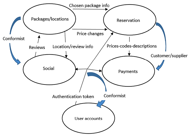
Figure 11.7: WWTravelClub domain map. Thin black arrows represent data exchanged between Bounded Contexts, while thick blue arrows represent the relationships between Bounded Contexts (conformist, customer/supplier, and so on)
For simplicity, we’ve omitted the Statistics reporting Bounded Context. Here, we’re assuming that the User accounts and Social Bounded Contexts have a conformist relationship with all the other Bounded Contexts that communicate with them because they are implemented with already existing software, so all the other components must adapt to them.
As we mentioned previously, the relationship between Reservation and Payments is customer/supplier because Payments provides services that are used to execute the tasks of Reservation. All the other relationships are classified as Partners. The various concepts of customer/user that most Bounded Contexts have are coordinated by the User accounts authorization token, which indirectly takes care of mapping these concepts between all the Bounded Contexts.
The Packages/locations subsystem not only communicates the packages information that’s needed to carry out a reservation/purchase—it also takes care of informing pending purchase orders of possible price changes. Finally, we can see that social interactions are started from an existing review or location, thereby creating communication with the Packages/locations Bounded Context.
Summary
In this chapter, we analyzed the main reasons for the adoption of DDD and why and how it meets the needs of the market. We described how to identify domains and how to coordinate the teams that work on different domains of the same application with domain maps. Then, we analyzed the way DDD represents data with entities, value objects, and aggregates, providing advice and code snippets so that we can implement them in practice.
We also covered some typical patterns that are used with DDD, that is, the repository and Unit of Work patterns, domain event patterns, CQRS, and event sourcing. Then, we learned how to implement them in practice. We also showed you how to implement domain events and the command pattern with decoupled handling so that we can add code snippets to real-world projects.
Finally, we used the principles of DDD in practice to define domains and to create the first sketch of a domain map for this book’s WWTravelClub use case.
In Chapter 12, Implementing Code Reusability in C# 10, you will learn how to maximize code reuse in your projects.
Questions
- What provides the main hints so that we can discover domain boundaries?
- What is the main tool that’s used for coordinating the development of a separate Bounded Context?
- Is it true that each entry that composes an aggregate communicates with the remainder of the system with its own methods?
- Why is there a single aggregate root?
- How many repositories can manage an aggregate?
- How does a repository interact with the application layer?
- Why is the Unit of Work pattern needed?
- What are the reasons for the light form of CQRS? What about the reasons for its strongest form?
- What is the main tool that allows us to couple commands/domain events with their handlers?
- Is it true that event sourcing can be used to implement any Bounded Context?
Further reading
- More resources on DDD can be found here: https://domainlanguage.com/ddd/
- A detailed discussion of CQRS design principles can be found here: http://udidahan.com/2009/12/09/clarified-cqrs/
- More information on MediatR can be found on MediatR’s GitHub repository: https://github.com/jbogard/MediatR
- A good description of event sourcing, along with an example of it, can be seen in the following blog post by Martin Fowler: https://martinfowler.com/eaaDev/EventSourcing.html