Networking Software
Sandeep Malik; Shreyansh Jain; Jaswinder Singh Digital Networking, NXP, Delhi, India
Abstract
In the past few decades the semiconductor industry has undergone a revolution. Initially, embedded devices were thought to have very limited capability, both in terms of processing power and memory. Most embedded devices were designed using microcontrollers rather than actual processors. Now a days the industry focus is mainly on the producing devices with raw processing power which can be used as a general purpose device or as an embedded networking device. This chapter will give an overview of networking and how the modern microcontroller and network processor devices are used in practical deployment. This chapter also allows users to get an overview of the network software development trends.
Keywords
Embedded Linux networking; Network stack; Embedded network devices; ethtool utility; ifconfig utility; ip utility; User space networking; DPDK; ODP; Microcontrollers; Fast-path
1 Introduction
In the past few decades the semiconductor industry has undergone a revolution. Initially, embedded devices were thought to have very limited capability, both in terms of processing power and memory. Most embedded devices were designed using microcontrollers rather than actual processors.
However, with an increased number of users exchanging data over the internet and with the increased availability of high-speed networks, the demand for high-processing embedded networking devices increased. This demand was also fueled by advances in semiconductor technology, which led to the computational power that is present in today’s devices being affordable.
This transition of embedded network products using microcontrollers to embedded network processors has gone through multiple phases. This evolution did not only focus on hardware but also on the complete ecosystem. Earlier embedded devices started by having most processing occur in the core. Then came an era in which network processing was subdivided into hardware and software. A subsequent stage introduced intelligent hardware accelerators that could be programmed for autonomous packet forwarding, post configuration. As technology continued to progress, processing power became cheaper, such that designs with custom accelerators became too expensive to design and develop.
These days, the industry focus is mainly on producing devices with raw processing power that can be used as general-purpose devices or as embedded networking devices.
2 Embedded Linux Networking
In the wake of technological advances, communication has become a vital requirement for a fully functional system. The requirement to have a communication network is now not just limited to legacy network infrastructure, involving core devices such as switches, routers, firewalls, or gateways; rather such networking functionality is becoming integrated in devices belonging to various new domains in a variety of forms.
For example, in the automotive world, the market is shifting toward autonomous cars with advanced connectivity requirements. These requirements are pushing the limits at which data is exchanged. To cater to such needs, connected cars are being designed with security gateways as a core component, responsible for controlling secure data exchanges between various components as well as with external cars on an as-needed basis. Since the use case of cars is a real-time use case, where data needs to be processed in a time-bound fashion, along with making sure that it is not compromised, having a security gateway as an integrated part is essential to the smooth operation of NextGen connected cars. This has opened up an entirely new domain with challenges involving real-time deadlines, data processing at high speeds with accuracy, and having security as a key component to ensure that malicious users do not hack into the internal vehicle network with devastating effects.
Another such requirement comes from the IoT domain. Due to the increased usage of the Internet and the availability of high-speed infrastructure, the number of devices and the amount of data that these devices have to exchange among themselves has increased multifold in last couple of years. Also, the adaptability of the IoT is acting as a catalyst for this. With the IoT coming into the picture, the estimated number of devices connected over the internet is in the order of billions. With so many devices in place, the need for embedded Linux networking is becoming more and more crucial. One important area in the IoT domain, where embedded networking plays a critical role, is “Edge Routing.” As IoT technology is evolving, the need for distributed computing power is coming to the forefront, wherein instead of relying completely on the cloud, some computational processing would be offloaded to edge routers which would eventually communicate on the north side with various sensors, actuators, and other devices, and on south side connect to the cloud network.
This chapter will start with an introduction into the core component of networking, namely the network stack in Linux. The introduction will cover the layered architecture of a network stack including a glimpse of both OSI and TCP/IP models. After the introduction, the chapter will consider various embedded network device use cases. Then it will shed light upon the tools that can be used in Linux to configure the networking aspects of the kernel. The chapter concludes by discussing the issues with Linux kernel–based networking.
2.1 Network Stack
The network stack in the Linux kernel is a core module which allows two systems, connected over a network, to communicate with one another. The network stack primarily defines a set of protocols which allows two entities to communicate with each other by following a set of rules. These rules primarily govern how the basic element flowing in the network, primarily known as a frame/packet, shall appear. The overall networking stack is implemented in the form of discrete layers where each layer is assigned a clear task. For the packets originating from the system, the task of a layer is primarily to encapsulate the information received from the upper layer, with an appropriate header, and pass it to the next layer until the packet is placed on a physical medium. In the reverse direction, each layer would extract the respective header before handing over data to the layer above.
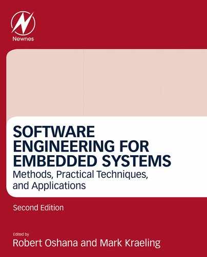
There are mainly two models used to represent the layered architecture of the Linux network stack. The first is called the OSI model and the second is popularly known as the TCP/IP model.
Fig. 1 depicts the OSI model and the protocols functioning in each of its layers.
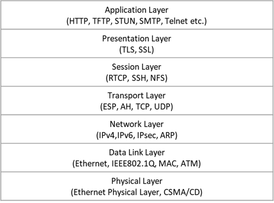
Now let us talk about the other model, namely the TCP/IP stack. This model envisions that complete functionality can be achieved even if we have five layers instead of seven, as in the OSI layered model. The TCP/IP model combines the highest three layers, namely the Application, Presentation, and Session Layers into one Application Layer. The designers of the TCP/IP model considered that the OSI model was overly layered and that a few layers could be combined to achieve a clearer, simpler design. Fig. 2 provides an overview of the TCP/IP model along with the protocols executing in each of its layers.
It is worth mentioning here that even though Fig. 2 shows only four layers, the numbering is such that the Application Layer is called L5 or Layer 5. Similarly, the Transport Layer is called L4 or Layer 4, the Network Layer is called L3 or Layer 3, and the Data Link + Physical Layer is called L2/L1, interchangeably.
The main advantage of the layered approach is that the task of packet handling has been distributed among different layers. Due to this, the maintainability of the code has increased and an issue originating in a particular layer will remain confined to that layer. This eventually helps with isolating software issues a little faster than a monolithic implementation. Details about the function of each layer are provided in great depth in both the online and offline literature and are beyond the scope of this chapter.
2.2 Embedded Network Devices
This section focuses on various use cases of embedded network devices. As mentioned in the Section 2.1, each layer has discrete responsibilities. This section touches on the family of network devices which are commonly used and also covers details such as which layer the device operates on or belongs to. In this section the layered architecture discussion is focused only on Ethernet devices.
Let us start with L1 or Layer 1 devices. These devices primarily work on the physical layer and usually are dumb devices without any frame-parsing capability. The data received on one port is religiously forwarded to other ports. There is generally no intelligence applied by devices operating on this layer. A Hub is one such device which operates at this layer.
Next comes L2 or Layer 2 devices. These devices focus on the L2 information which is primarily comprised of MAC addresses. These devices permit frames to allow or drop on the basis of the MAC address associated with that frame. A Switch is one of the commonly used network devices operating at Layer 2. A switch can be thought of as an intelligent hub which can educate itself based on the MAC addresses learned from the packets received on its ports and post awareness will not flood traffic to other ports. A switch usually maintains forwarding database tables where the mapping of MAC address and ports is stored. This mapping helps in deciding upon the destination of a particular stream.
Layer 3 devices focus on the destination IP address in the packets to decide on the action to be taken for a frame. The action depends on whether the destination IP address is a self IP or some other IP. In the case that it is a self IP, the packet gets delivered locally to a host. In the case of an IP address not matching the self IP, the device tries to find a route for this traffic, including if the destination belongs to a subnet of any interface IP. In the case that a match is found the packet is forwarded to that interface or else the system checks whether there is a default route configured in the system. If a default route exists, the packet is forwarded, otherwise the packet is discarded. Sometimes the routing decision may involve modified IP addresses in the case that a NAT (network address translation) is configured. A NAT is not limited to Layer 3, rather it spreads from Layer 3 to Layer 5 depending on the configuration. Since this layer is primarily involved in finding the route for the next hop, devices which operate in this layer are called Routers.
Layer 4 devices operate on five-tuple information, including IP source address, IP destination address, protocol, source port, and destination port. The packet undergoes various processing stages/lookups before coming out of a particular port. The stages typically help with the acceptance or rejection of the flow based on the firewall rules configured in the system. Network devices that operate at this layer are called Firewalls.
Layer 5 devices operate on the complete packet, including the payload, to make a decision. These devices are highly intelligent devices and are typically deployed in areas of deep-packet inspection or work as proxies. Such devices, if working as proxies, are typically called Application Layer Gateways or if working in areas of deep-packet inspection are called Next Generation Firewalls.
2.3 Network Configuration and Analysis Utilities
This section considers the various utilities which help configure networking services on a Linux-based embedded network device. The utilities discussed in this section are all open-source utilities and a plethora of literature about them is already available online. Some of the references about useful resources are also available in the “Further Reading” section of this chapter.
ethtool: This utility allows the user to view and update the properties of a network device and a few properties supported in the device driver. This utility is widely used across the community to peep into the network device. A sample output of the ethtool command follows.
When the device link is not up:
ethtool eth0
Settings for eth0:
 Supported ports: [ ]
 Supported link modes:  Not reported
 Supported pause frame use: No
 Supports auto-negotiation: No
 Advertised link modes: Not reported
 Advertised pause frame use: No
 Advertised auto-negotiation: No
 Speed: Unknown!
 Duplex: Half
 Port: Twisted Pair
 PHYAD: 0
 Transceiver: internal
 Auto-negotiation: off
 MDI-X: Unknown
 Current message level: 0xffffffff (-1)
drv probe link timer ifdown ifup rx_err tx_err tx_queued intr tx_done rx_status pktdata hw wol 0xffff8000
 Link detected: no
When the device link is up:
ethtool eth0
Settings for eth0:
 Supported ports: [ MII ]
 Supported link modes:  10baseT/Full
  100baseT/Full
  1000baseT/Full
 Supported pause frame use: Symmetric Receive-only
 Supports auto-negotiation: Yes
 Advertised link modes: 10baseT/Full
  100baseT/Full
  1000baseT/Full
 Advertised pause frame use: Symmetric Receive-only
 Advertised auto-negotiation: Yes
 Speed: 10Mb/s
 Duplex: Half
 Port: MII
 PHYAD: 28
 Transceiver: external
 Auto-negotiation: on
 Current message level: 0xffffffff (-1)
 drv probe link timer ifdown ifup rx_err tx_err tx_queued intr tx_done rx_status pktdata hw wol 0xffff8000
 Link detected: no
More details about ethtool command parameters form part of the Linux man pages.
ifconfig: Another popular utility, widely used by network administrators as well as individual users for configuring network device parameters, is ifconfig. This utility allows the configuration of the network interface, specifically the IP address, MAC address, and devise status, to be either up or down. A sample output of the ifconfig command follows.
- root@t1040qds:~# ifconfig
- eth0 Link encap:Ethernet HWaddr 00:e0:0c:00:58:00
- inet addr:192.168.2.108 Bcast:192.168.2.255 Mask:255.255.255.0
- inet6 addr: fe80::2e0:cff:fe00:5800/64 Scope:Link
- UP BROADCAST MULTICAST MTU:1500 Metric:1
- RX packets:0 errors:0 dropped:0 overruns:0 frame:0
- TX packets:3 errors:0 dropped:0 overruns:0 carrier:0
- collisions:0 txqueuelen:1000
- RX bytes:0 (0.0 B) TX bytes:238 (238.0 B)
- Memory:fe4e0000-fe4e0fff
- lo Link encap:Local Loopback
- inet addr:127.0.0.1 Mask:255.0.0.0
- inet6 addr: ::1/128 Scope:Host
- UP LOOPBACK RUNNING MTU:65536 Metric:1
- RX packets:13 errors:0 dropped:0 overruns:0 frame:0
- TX packets:13 errors:0 dropped:0 overruns:0 carrier:0
- collisions:0 txqueuelen:0
- RX bytes:1456 (1.4 KiB) TX bytes:1456 (1.4 KiB)
- root@t1040qds:~# ifconfig eth0 down
- root@t1040qds:~# ifconfig
- lo Link encap:Local Loopback
- inet addr:127.0.0.1 Mask:255.0.0.0
- inet6 addr: ::1/128 Scope:Host
- UP LOOPBACK RUNNING MTU:65536 Metric:1
- RX packets:13 errors:0 dropped:0 overruns:0 frame:0
- TX packets:13 errors:0 dropped:0 overruns:0 carrier:0
- collisions:0 txqueuelen:0
- RX bytes:1456 (1.4 KiB) TX bytes:1456 (1.4 KiB)
The ifconfig utility is part of the nettools package.
Note that there are other useful utilities which are part of the nettools package, including arp, netstat, and route. These utilities are also worth exploring.
ip: This section considers another utility named ip. This allows the user to play with not only the interface related parameters but also some advanced functions like route configuration. This utility is a part of the “IPROUTE” package.
This utility provides features of multiple nettools utilities, such as arp, ifconfig, and route, using a single interface. Some sample commands executed using the ip utility follow.
- root@t1040qds:~# ip -s neigh
- root@t1040qds:~# ip neigh add 192.168.2.10 lladdr 1:2:3:4:5:6 dev eth0
- root@t1040qds:~# ip -s neigh
- 192.168.2.10 dev eth0 lladdr 01:02:03:04:05:06 used 2/2/2 probes 0 PERMANENT
- root@t1040qds:~# ip route
- 192.168.2.0/24 dev eth0 proto kernel scope link src 192.168.2.108
- root@t1040qds:~# ip route add default via 192.168.2.1
- root@t1040qds:~# ip route
- default via 192.168.2.1 dev eth0
- 192.168.2.0/24 dev eth0 proto kernel scope link src 192.168.2.108
This section lists the two most popular utilities used by hackers and network programmers for sniffing packets in the network.
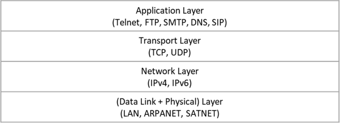
tcpdump: This utility is very useful to debug and to root out the causes of problems related to traffic entering the Linux box. This utility allows the user to monitor packets on a specific interface in real time, irrespective of whether the interface is wired or wireless. This also allows the user to redirect packet captures in a file which can later be viewed using any tool, like wireshark, or played using tools like tcpreplay. The following snapshot shows a typical view of a system running the tcpdump utility to capture packets when ping is initiated on an interface.
More information about the tcpdump utility can be found on the main pages in Linux.
wireshark: Another very widely used utility, similar to tcpdump, is known as wireshark, aka ethereal in its early days. The wireshark/ethereal utility is usually installed in Linux box by default but can be installed easily in cases when it is not present since almost all Linux distribution offers this utility’s installer. It provides an easy-to-use graphical interface which allows the user to add filters in order to select the display of a specific packet stream or a specific protocol from all captured packets. Below is a snapshot of the wireshark tool capturing packets on a live network interface.

Further details about the usage and capturing capability options of wireshark can be found on the wireshark website.
3 Moving From the Linux Kernel to User Space
The Linux networking stack is a very large block that enables almost all the well-known protocols active today. It enables the Kernel to read a packet, process its various headers, and perform operations like handing over a user space application or forwarding ahead. However, being a general-purpose operating system, the Linux network stack includes a much larger set of functionalities than generally used. The design tenets which Linux attempts to achieve impacts the design of the network stack as well:
- 1. Inherent support for a large set of protocols and devices. The use cases which the Linux kernel supports are very wide ranging—from embedded devices to large supercomputers. With such a large set comes the need to support an even larger number of protocols, irrespective of the density of deployment. The Linux networking stack supports a huge number of protocols—some of which enable the Internet (TCP) and others that are specific to domains like the IoT (e.g., 6lowpan).
- 2. Compliance and quality assurance. With such a large user base comes the responsibility to be compliant to industry standards. This requires rigorous verification, both in implementations and deployments. This makes the kernel reliable and its network stack standardized. This also leads to long development and mainline timelines for new devices or protocol support.
Performance as a criterion sits on a lower priority strata than flexibility, scalability, and adaptability, which the kernel strives to achieve. Though the Linux kernel can be used in innumerous generic scenarios, it is not an adequate solution for some specific problems—more precisely, problems around achieving line rates or an adequate utilization of a network fabric.
Upcoming use cases and subsequent advancements in network infrastructure have long out-paced the development of the Linux kernel network stack’s ability to keep up with the available bandwidth and latency requirements. For example, in the case of high-frequency trading (HFT), the available margin of packets is much lower than the performance achieved by the Linux kernel-based environment. The focus on reliability and compliance is not a primary criterion.
The general reasons for Linux network stack’s unsuitability are:
- 1. Its performance is not able to keep up with the network fabric available in the market. It cannot reach line rates for raw packet performance on many of the hardware NICs (like Intel XL710 with 40G interfaces).
- 2. Its lack of flexibility to adapt to new protocols or packet types—at least through mainline support. It is always possible to hack into the kernel, but that is a risky approach given that it impacts system stability.
- 3. Its inability to keep up with the lightning fast times to market required by organizations and their eventual customers, associated with rapid advancements in hardware technology in compliance with an increasing number of use cases.
3.1 Analyzing the Expected Packet Rates
For a 1-G line card, the maximum theoretical throughput that can be achieved is 1.448 million packets per second (Mpps). This is based on the fact that the smallest packet would be 84 bytes, including the preamble and IFG (interframe gap). This implies that to achieve line rate, the CPU (or the packet processing engine, in its entirety) should be able to process 1.44 million packets per second. For a 10-G link, that would be 14.88 Mpps.
1 Gbps = 1 x 1000 x 1000 x 1000 bits per second = 1000,000,000/8 bytes per second = 125,000,000 bytes per second
With minimum packet size of 84 bytes = 64 bytes + 12 bytes preamble + 8 bytes IFG = 67.2 ns processing time to achieve line rate
For processing that number of packets, about 67.2 ns are available for the packet processing engine to perform processing on the packet.
For a NIC card capable of a 10-G line rate, the average time available for processing each packet, so as to achieve line rate, is about 67.2 ns.

In the above image, extracted from https://people.cs.clemson.edu/~westall/853/tcpperf2.pdf, the RX path of a packet in a Linux stack has been described.
The costliest operation, shown in this figure, is the “kernel protocol stack”—which parses each packet and finds the appropriate application to hand it over to, using the socket interface. This operation is expensive because it supports a very large number of protocols, most of which are not used in the majority of use cases. This makes the Linux Kernel an ideal stack for deployment in a large number of use cases—however, performance is sacrificed. Usually, over a 10-G NIC, approximately 1–2 Mpps can be processed by a kernel stack on a general 2-GHz processor.

In case the number of protocols supported is not required and the complexity of the stack does no’t add any value to the use case, it is possible to completely bypass the stack. There are proven solutions which showcase performance at line rate for supported NICs. These solutions either completely bypass the Linux kernel network stack or just use it as a secondary or fallback option—performing protocol-specific operations.
The following text outlines what is required to achieving the best performance outside of the Linux network stack.
3.2 Direct Access to the Hardware
The primary reason the network path of a packet through a Linux kernel is not considered optimal is the thickness of the layers between the actual hardware receiving the packet and the application consuming the packet.
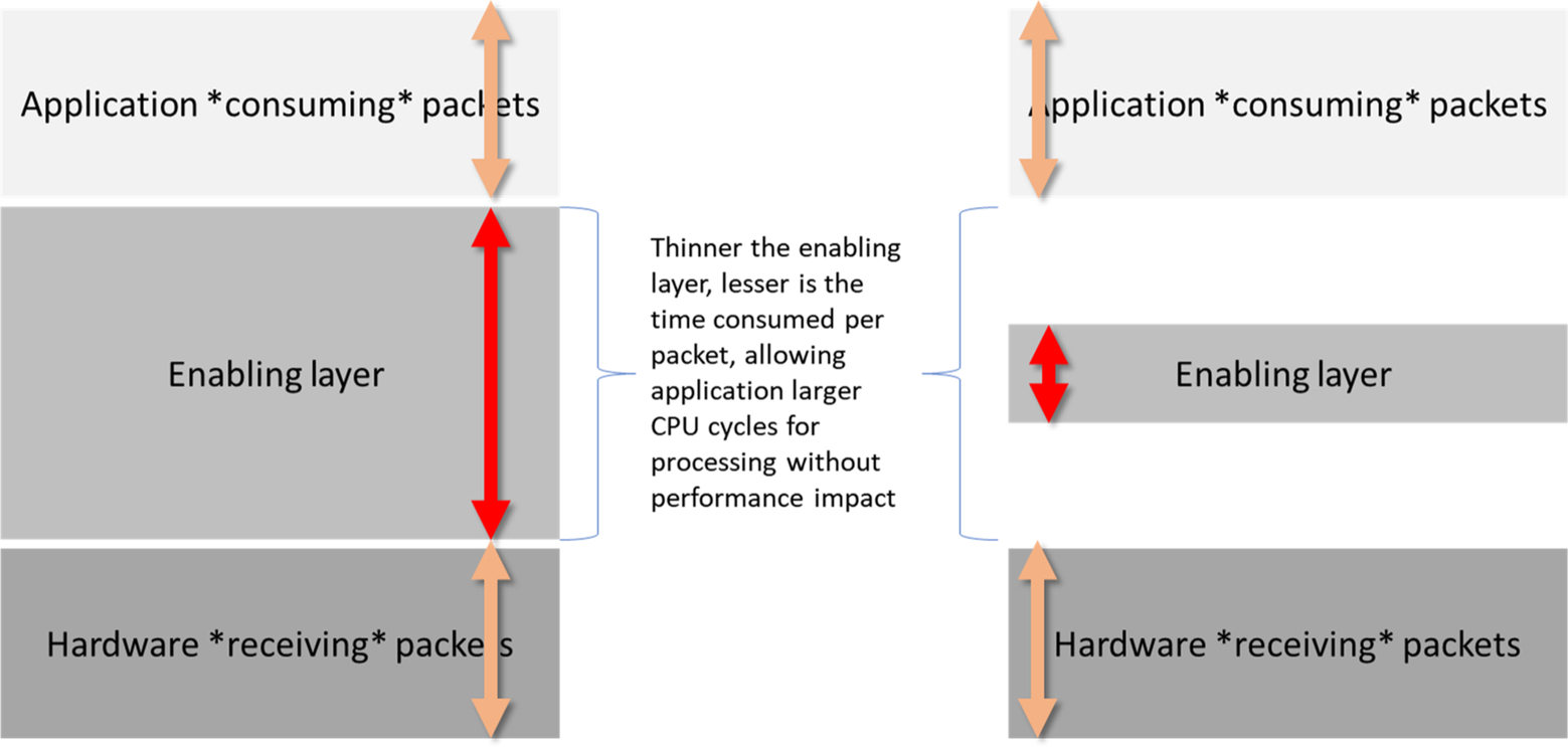
Various solutions propose thinning this layer of its “enabling software or layers,” allowing more CPU time for applications to write their custom logic. Some solutions work directly with hardware registers, configuring them with optimal values based on use cases. Other solutions work with very thin layers of abstract APIs, which hide hardware complexities. However, in both cases, the challenge is to expose the hardware to the application.
Solutions like DPDK and ODP rely on the user space access of the hardware through memory mapping. Whereas, solutions like XDP and Netmap use a thin set layer in the Linux kernel (kernel module) for enabling access. Further, solutions like eBPF go a step further and provide in-kernel execution of custom code within the kernel scope.
3.3 Virtual I/O Layer (VFIO/UIO) and HugePages
Two of the Linux kernel’s concepts, VFIO/UIO and HugePages, play a big role in enabling the user space access to devices.
Virtual function I/O or VFIO and user space I/O or UIO represent the Linux kernel’s ability to expose a device to the user space through file-based interfaces from sysfs. A device, if bound to a VFIO/UIO driver, exposes its configurable memory space to the driver. Thereafter, the VFIO/UIO driver would allow any user space application to read the memory space and map it in its own address space. All this is done through the standard file open/close/read/write/ioctl interface.
At the same time, HugePages support in the Linux kernel allows the application to pin to memory large chunks of address space, which have larger than usual page sizes (2 MB, 4 MB, 1 GB, etc.). This increases the performance of accessing an address for I/O from a device by reducing the spread of data across multiple page counts.
3.4 Receiving Packets Through Device Polling or Events From Device
The methodology for receiving packets by an application is another arena for performance improvement. In the case of the Linux network stack, sockets are exposed which can either work in polling mode or in an event, that is, waiting for events to occur. Similarly, for those solutions which bypass the Linux stack, there are two broad ways to receive network packets—either by continuous polling of the hardware interface or by events generated by the hardware interface.
As CPUs become cheaper and faster, network applications can utilize more compute bandwidth without impacting overall system performance. In such cases, continuous polling, which otherwise is expensive, proves to be a performant alternative. Yet, in many small or edge devices hosting a network application, where CPUs are a precious resource, event-based packet reception models work well.
The following section considers a few of those solutions, that is, ODP, Netmap, DPDK, XDP, and BPF. Of these, ODP, Netmap, and DPDK are primarily used for performance extraction but XDP and BPF are used for enhancing Linux network stack ability through external plugins and programmability.
3.5 ODP—Open Data Plane
ODP or OpenDataPlane is an open-source project under the Linaro umbrella which aims to provide a cross-platform set of application programming interfaces (APIs) for the networking data plane. It leverages vendor-specific hardware blocks and their implementation and layers a generic set of APIs exposed to the applications. The intent is to create network data plane applications which are agnostic to underlying hardware and yet able to extract the best hardware support.
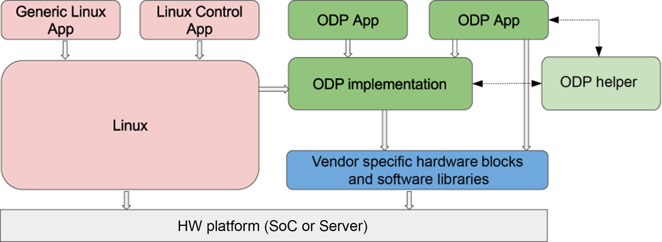
From: https://opendataplane.org/index.php/service/technicaloverview/
In the image above, green blocks represent the ODP high-level components compared with the Linux stack and vendor hardware.
ODP is a C-based framework. A typical ODP application would be similar to the following snippet:
int main(int argc, char *argv[]) { odp_init_t init; odph_odpthread_t thr; /* Install some kind of signal handler as thread would be * infinite loop */ signal(SIGINT, sig_handler); ... /* Global initialization */ if (odp_init_global(&instance, &init, NULL)) { LOG_ERR("Error: ODP global init failed. "); exit(EXIT_FAILURE); } /* Initialization for a local thread, to be done for each * thread created. */ if (odp_init_local(instance, ODP_THREAD_CONTROL)) { LOG_ERR("Error: ODP local init failed. "); exit(EXIT_FAILURE); } ... /* Create a pool of buffers which would be used by * hardware for packets – ethernet, crypto, etc */ odp_pool_t pool = odp_pool_create("packet pool", ¶ms); ... /* Create a pktio device – essentially representing a hardware device * which would Rx and Tx data packets. Like Ethernet or Crypto. * This function also initializes any queues attached to the pktio * device. */ if (create_pktio(dev, i, num_rx, num_tx, pool, grp)) exit(EXIT_FAILURE); ...
 /* Create an ODP worker thread – which would essentially do I/O.
 * ‘thr_params’ would contain thr_params.start = < some_IO_func > */
 odph_odpthreads_create(thr, &thd_mask, &thr_params);
 ...
 /* At this point, the workers threads are awaiting device start */
 odp_pktio_start(pktio)
 ...
 /* Collect some stats */
 /* When done, stop the Pktio device */
 odp_pktio_stop(pktio);
 ...
 odp_pool_destroy(pool);
 odp_term_local();
 odp_term_global();
 return ret;
}

static int create_pktio(char *dev_name, odp_pool_t pool, int num_tx_queue,
  int num_rx_queue)
{
 odp_pktio_t pktio;
 pktio = odp_pktio_open(dev, pool, < some params >);
 ...
 /* Initialize the parameters which would be used for configuring the
 * Rx and Tx queues. */
 odp_pktin_queue_param_init(< Rx queue params >);
 odp_pktout_queue_param_init(< Tx queue params >);
 ...
 /* Configure the queues */
 odp_pktin_queue_config(pktio, < Rx queue params >);
 odp_pktout_queue_config(pktio, < Tx queue params >);

 /* Eventually, enable the queues, ready when odp_start is called */
 odp_pktin_queue(pktio, < Queue configured >);
 odp_pktout_queue(pktio, < Queue configured >);
 ...
}

static int some_IO_fun(void *arg)
{
 odp_queue_t queue;

 /* Queue would have been initialized to */

 while (< signal not received >) {
    /* Receive packet on a queue */
    pkts = odp_pktin_recv(rx_queue, pkt_buffer, < num of buffers >);
    /* Send it out of another queue */
    sent_pkts = odp_pktout_send(tx_queue, pkt_buffer, pkts);
    /* Release the packets which were sent */
    odp_packet_free(pkt_buffer[sent_pkts]);
 }
}
In the above snippet, there are various functions represented by the odp_* naming convention. These are ODP APIs which define an abstract layer over a complex hardware-dependent code. These APIs can be broadly categorized into following sets based on their functionality:
- 1. Initialization APIs.
- 2. Packet and packet I/O for representing a packet and an interface over which packets are either received or transmitted.
- 3. Buffers and buffer pool for representing a block of memory for holding packets or other metadata, arranged in a pool for efficient allocations and deallocations.
- 4. Queue for representing the serialized packet interface connected to an I/O device.
- 5. Scheduler which represents a software logic which controls the next queue to serve, based on prioritization or order.
There are various other blocks like Crypto, Hash, and Traffic Management, used for tying together functionalities to create a solution.
ODP’s primary aim is to create a uniform set of APIs. All the implementation is left for hardware owners to handle, including any specialized libraries like hashing and distribution. These allow hardware owners to focus on their implementation without integration issues. This also enables gluing together two or more underlying bits of hardware (if supported layers are present) with a high degree of interoperability. Furthermore, this strategy also enables a fast time-to-market for hardware vendors as they only have to integrate their implementations with a uniform set of APIs.
3.6 DPDK—Data Path Development Kit
DPDK was originally an Intel project but was open sourced (BSD) in 2010 as a stand-alone project. In the year 2017, it merged with the Linux Foundation. As mentioned online (https://www.dpdk.org/about/in), “Since then, the community has been continuously growing in terms of the number of contributors, patches, and contributing organizations, with 5 major releases completed including contributions from over 160 individuals from 25 different organizations. DPDK now supports all major CPU architectures and NICs from multiple vendors, which makes it ideally suited to applications that need to be portable across multiple platforms.”
Whereas ODP focuses on abstraction of APIs, DPDK focuses on performance through optimization of general-use functionalities. ODP allows hardware owners to completely focus on their implementation, with all their support libraries—whereas, DPDK architecture allows hardware owners to off-load generic operations to an already available optimized set of libraries, allowing them to focus completely on core I/O paths.
However, both solutions are classic examples of frameworks for user space acceleration packets from network and nonnetwork (crypto, compression, etc.) blocks.
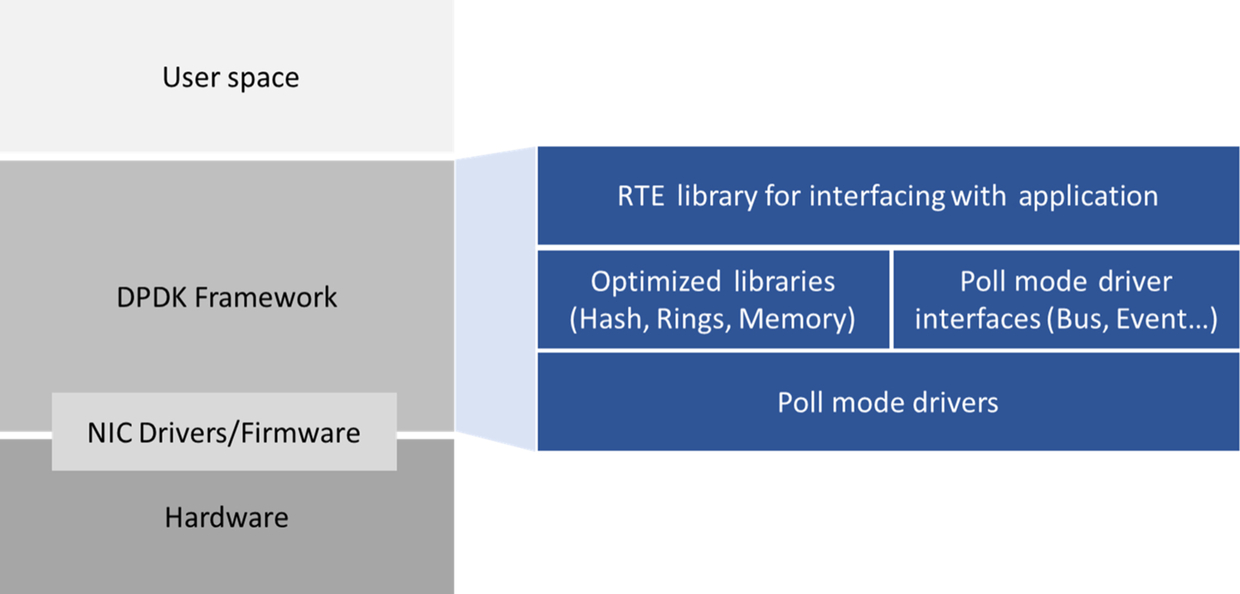
The primary logic of controlling network devices is contained within the “DPDK Framework” layer. This in turn is composed of multiple libraries, each for a specific function, such as Hash Table, Ring, GRO, GSO, Fragmentation, and Classification. This is glued together with NIC specific drivers in user space for enabling and devices. The library is also referred to as RTE and EAL, which stands for RunTime Environment (RTE) and Environment Abstraction Layer (EAL), respectively.
Just like ODP, DPDK is also a C language-based framework. A typical program in DPDK would be similar to the following snippet:
int main(int argc, char *argv[])
{
 ...
/* Initialize the EAL framework; This initializes all the necessary components like memory, threads and command line arguments for device parameters. */
 ret = rte_eal_init(argc, argv);
 ...
/* Those arguments which are consumed by rte_eal_init are the ones passed to the framework. Separated by a ‘--‘, all the application specific arguments can be provided which would remain untouched by EAL framework. */
 ret = parse_args(argc, argv);
 ...
 /* Find the number of ports which were detected by the EAL layer. */
 nb_ports = rte_eth_dev_count_avail();
 if (nb_ports == 0) {
 printf(“No ports were detected
”);
 return -1;
 }
/* Applications can also find a port using its name. This API would return a port ID number which can then be used to reference the port. */
 ret = rte_eth_dev_get_port_by_name(name, &portid);
 ...
/* Create a pool for Rx/Tx of packets; This pool would be attached to the device/port and when driver Rx’s packets, memory would be allocated from this pool. Similarly, the application can use this pool to allocate memory (rte_mbuf) from this pool. */
 pktmbuf_pool = rte_pktmbuf_pool_create("mbuf_pool", nb_mbufs,
  MEMPOOL_CACHE_SIZE, 0, RTE_MBUF_DEFAULT_BUF_SIZE,
  rte_socket_id());
 if (l2fwd_pktmbuf_pool == NULL)
 printf(“Error; Not enough memory to work with
”);
 ...
 ...
/* Then, for each port, configure it. This can also be replaced with a logic for a specific port fetched from rte_eth_dev_get_port_by_name(). */
 RTE_ETH_FOREACH_DEV(portid) {
struct rte_eth_dev_info dev_info;
    /* Get the port information, which includes its name, limits (number of queues, buffer and ring sizes, capabilities and other information based on which application can define its configuration parametres. */
rte_eth_dev_info_get(portid, &dev_info);
    /* Creating a local set of configuration based on fetched set to configure the device. If the values of configuration exceed those specified in the rte_eth_dev_info_get API, the configuration can return an error. */
    struct rte_eth_dev_info local_info;
    /* for example, for enabling VLAN stripping on Rx’d packets, after checking if that is supported or not... */
    if (dev_info.rx_offload_capa & DEV_RX_OFFLOAD_VLAN_STRIP)
  local_info.rxmode.offloads |= DEV_RX_OFFLOAD_VLAN_STRIP;
 ...
    /* Configure device with n_rx and n_tx number of Rx and Tx queues, respectively. */
    ret = rte_eth_dev_configure(portid, n_rx, n_tx, &local_conf);
 ...
    ret = rte_eth_rx_queue_setup(portid, 0, n_rx, < Socket ID >, rxq_conf, pktmbuf_pool).
3.7 BPF—Berkley Packet Filter
Most packet processing software stacks focus on working on the packets either in Kernel space (drivers, Linux TC, XDP) or in user space (DPDK, ODP). The eBPF, or Berkley Packet Filter, is a novel approach which focuses on reducing the overhead of copying packets from the Kernel to user space by using “Packet Filters” which are capable of processing packets as early as the software queue but without the complexity associated with a Linux Kernel network driver.
This method was first proposed way back in 1992 (http://www.tcpdump.org/papers/bpf-usenix93.pdf). The original proposal talks about providing a limited set of instructions, called a “filter machine,” which are available to be plugged and configured from user space. The authors implemented a register-based RISC emulator which traps the limited instruction set of the binary blob used for process packets. This filter is executed within the context of the kernel. Such filters are invoked on each arriving packet, and the result of the filter is passed to some user space application to make a decision (if not already made by the filter logic).
This approach of creating a pseudo virtual machine, with a limited instruction set, within the Linux kernel was unique to the packet-processing scene. In recent times, it was improved with the introduction of eBPF or enhanced BPF. The virtual machine now employs instructions closer to the hardware for data movement in register-sets. Consequently, the filter sets written can use more advanced compare, load, and store operations.
4 Life of a Packet in a Native Linux Network Stack
This section discusses the details of the life of a packet in a Linux-based system. A packet first enters the NIC card that usually has a DMA engine responsible for dumping packet data into the buffers that belong to its internal memory in the case that it is an autonomous IP acting as an accelerator, or the DDR in the case that packet processing is done at the CPU. For the sake of simplicity and explanation this section covers the latter case, where buffers are from DDR and packet processing is done at the CPU. To be more precise this section discusses the receive path where a packet is delivered to the application running on the core after being received by an Ethernet driver.
The complete receive path can be thought of as consisting of three major components. First, the NIC and the Ethernet driver; second, the kernel network stack; and third, the application or the consumer of the packet.
In the first stage, the NIC card receives a packet which will eventually be processed by the network driver and performs the functions of Layer 1 and Layer 2 of the OSI layer architecture. The general architecture for the NIC consists of a DMA engine and a set of rings which have buffers to receive the packets. The following figure is a high-level view of the system. The NIC card DMAs the data received from the network into the buffers attached to the buffer descriptor ring and sets the status to FULL. In above diagram the filled buffers have been grayed out. At the same time, it also raises an interrupt to the core—a hardware interrupt. This interrupt eventually triggers the invocation of the NETIF_RX softirq which is responsible for dequeuing the buffer from the ring and replenishing it with a new empty buffer. These buffers then are handed over to a higher layer for further processing. In the case that there are no free buffers available, the incoming packets are discarded.

In the second stage, the buffer is processed by the Linux network stack where the packet is processed by different protocol layers such as IP, IPsec, TCP, or UDP. The driver invokes the standard Linux network stack API to hand over the packet to the kernel. Initially, the IP layer completes integrity checks on the IP header. Once the packet is found to be valid, it is then checked against the forwarding database to see if it should be forwarded to another hop or handed over to some application running on the system. The application could be listening on a TCP or a UDP socket in which case the packet would be picked by the application using an interface.
In the third and final stage, the data is received by the application from a socket’s receive buffer and is copied to user space memory with the help of standard Linux interfaces like struct iovec and other related calls like copy_to_user. Based on the protocol used for communicating with user space, processing may also start in the context of process dequeuing of the buffers. However, if packets are targeted for forwarding to the next hop, all processing from dequeuing the buffer from the receive buffer descriptor ring to finally putting the packet back into the transmit buffer descriptor ring for transmission, is done in the same context as NETIFRX_SOFTIRQ.
5 Networking Performance Optimization Techniques
Optimizing networking performance is a challenging task and requires planning that starts at the networking system architecture design level. As there are a variety of embedded network devices ranging from ultra-low-end microcontrollers to low-end single-core network processors to mid-end 2–4-core embedded network processors to high-end (having more than 24 cores) network processors a single set of optimization techniques can't be used to fix performance issues for all implementations. In this section the emphasis is to share an architectural overview of both hardware and software.
5.1 Architecture Overview of Network Packet Processing
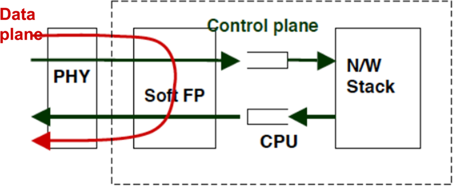
Network packet processing is generally divided into three planes, namely the management plane, control plane, and data plane. Usually the networking device implements the data plane in the hardware using various entities called forwarding engines (Fig. 3).

These forwarding engines can be designed for dedicated processing, for example, one forwarding engine doing the L3 forwarding and another engine dedicated to packet inspection and the firewall. Similarly, there can also be a forwarding engine dedicated to IPsec processing. These forwarding engines usually maintain flow contexts to provide respective services. Each of the forwarding engines caters to multiple flow contexts. These flow contexts are usually programmed by the control plane.
The creation of a flow context can be done either on need basis; when a flow enters system and the forwarding engine doesn't have a flow context entry. The packet is given to the control plane, which initiates the process of the creation of a flow context entry in the forwarding engine. Once the flow context is created, the next packet is served by the forwarding engine.
Another way to create a flow context is to initiate the process even before the packet enters the system. In this case, the control plane creates flow contexts and whenever a packet enters it finds the matching flow context and is handled by the forwarding engine without intervention of the control plane.
The information stored in the flow context varies based on the service it is catering to. For example, in the case that the forwarding engine is catering to the L2 bridge or switch service, the flow context usually stores the destination MAC address and outbound port for that flow. The flow context usually has a lifetime associated with it, meaning that if no packet matching a flow enters the system, the flow context will be deleted, post lifetime expiry, to make space for a new flow. Whenever a matching packet for a flow enters the system, the flow context timer is refreshed, allowing the entry to be alive.
The control plane has multiple control engines which are usually implementing protocols responsible for interacting with other networking endpoints. The control plane is responsible for handling the exception packets coming from the forwarding engine. The exception packets are usually packets for which a matching flow context is missing in the forwarding engine. On receiving an exception packet, the control plane initiates the process of flow context creation in the forwarding engine.
The outcome of the interaction between the two entities eventually triggers flow context creation in the forwarding engine.
5.2 Network Packet Processing Implementation
Now that we have learned about the basic building blocks involved in network packet processing, let’s consider the methods that can be used to implement network packet processing solutions. Since the processing of networking traffic involves multiple components, software can be designed to work either to have all the processing done in a single core or break packet processing across multiple cores, such that each core does a certain part before handing over the packet for further processing to the next core, and so on.
A programming model where packet processing is divided into multiple components being executed to different cores is called pipeline processing. This kind of implementation has severe implications on aspects of performance. With such an implementation, the overall performance of a system is limited by the slowest component involved in the complete processing. Also, this kind of implementation induces lots of delays in packet processing. Complexities may arise in cases where there is a mismatch between processing modules and the number of cores available. This would require the identification of components that can be further broken down or can be merged, based on core availability. Identifying and breaking or clubbing the components is not an easy task in most instances.
The other model involves complete packet processing done on a single core. This processing model gives flexibility in terms of taking advantage of the multiple cores available in the system to deliver best performance. However, even in this case, based on the nature of traffic tweaking, there is a requirement that packets belonging to a particular flow are processed by a particular core, otherwise packets belonging to a particular flow may start going out of order.
5.3 Considerations for Optimized Network Packet Processing
Network packet processing can be optimized by having a dedicated hardware component, wherein complete processing can be off-loaded. The off-load to hardware can be controlled by software. Whenever a new flow enters the system, the control plane programs the underlying hardware with details about the flow, such that going forward the hardware block can autonomously handle the packets. A high-level diagram showing such an arrangement is provided below.

Such dedicated bits of hardware are usually called network coprocessors or packet processing engines. These can be designed in such a way as to be programmed via standard interfaces or may provide a proprietary interface. In an advanced multicore network processor there could be multiple hardware blocks handling a variety of traffic. These hardware blocks are primarily required for two reasons: first, they help in off-loading packet processing otherwise done on the CPU; and second, they help in achieving line rate without consuming CPU cycles. These acceleration IPs are usually dedicated to a specific task—one IP only doing network-related processing with another involved in security-related processing.
Another approach to achieve optimized network packet processing is to have a software module designed to imitate the dedicated hardware coprocessor. What this means is that the software module would provide APIs that can be called by the control plane to off-load flow-related information.
Based on this information the software module indigenously starts processing packets. This avoids lots of checks that every packet undergoes if processed by the normal flow in Linux. Based on the capabilities provided by this software, it needs to register for hooks at different points in the Linux stack. For example, if the module provides only firewall/router functionality, it needs to be aware of any flow creation or any firewall rule change happening in the Linux subsystems. Similarly, if the module is also providing IPsec-related processing, it registers hooks in the Linux XFRM infrastructure to be aware of the changes happening in the security policy database (SPD) and security associations (SA). In the next section we discuss at a higher level the implementations used in actual deployments to achieve the goal of fast packet processing.
5.4 Application-Specific Fast-Path (ASF) for Linux
This section captures some high-level detail about ASF implementation for Linux by NXP. The intent of ASF is to accelerate data plane packet processing for the most commonly used functionalities, such as IPv4 forwarding, NAT, firewall, and IPSEC. Here, control plane processing is still handled by the Linux networking stack, while fast data path packet processing is completed in ASF. The figure below gives an overview of the layered architecture of ASF.
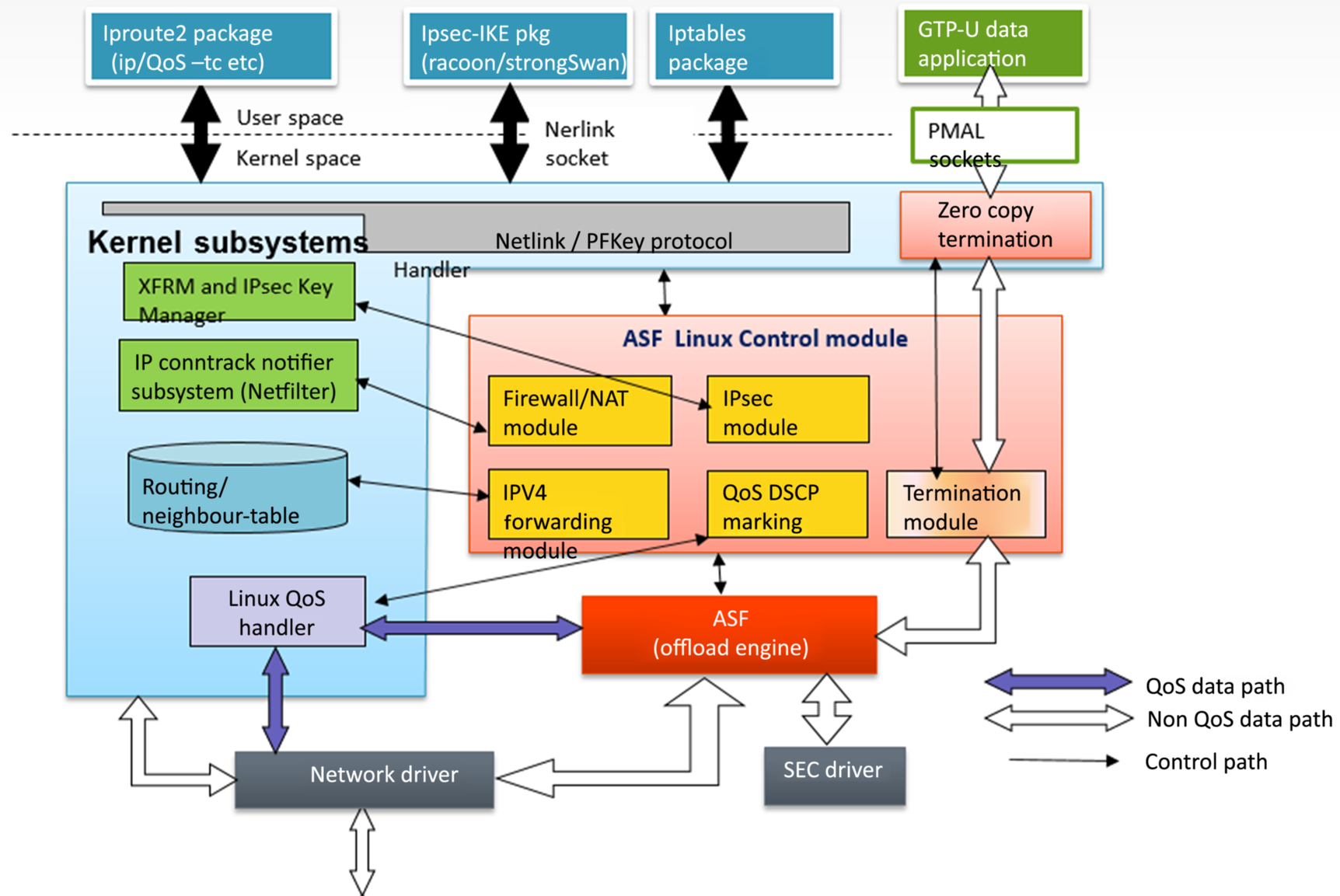
In the above diagram the red-colored boxes constitute the software module providing the packet acceleration capability, in its entirety called the ASF. So, there is a control logic which sits in the Linux network subsystem and there is fast-path processing logic which can either be in the form of a loadable kernel module or can be built as a static module.
All the packets entering the system are forwarded from an Ethernet driver to the ASF module. In the ASF module, a given packet flow (based on L2/L3/L4 header information) is checked in ASF lookup tables, which become populated through the ASF control module. If a matching flow is found for a received packet, it is processed as per the action configured for that flow and is forwarded to the configured egress interface or terminated locally.
ASF can cater to various use cases ranging from IP forwarding, firewall, NAT, QoS, and IPSec. Let us consider an example and delve into the details of the IPsec use case. For IPsec, ASF control module registers hook into the IP XFRM framework of Linux, via Key Manager, to receive notifications about any updates happening in SPD or SA databases. Whenever a new security policy or a new security association is created in Linux, an ASF control module callback notifier function is invoked to make any required updates. This update notification triggers an update of the database maintained in the ASF module. This notifier is invoked for every addition/deletion/modification to the database. The following is a snippet showing how to register for an event notification in case of any change in the database.
static struct xfrm_mgr fsl_key_mgr = {
 .id   = "fsl_key_mgr",
.notify  = fsl_send_notify,
 .acquire  = fsl_send_acquire,
.compile_policy = fsl_compile_policy,
 .new_mapping = fsl_send_new_mapping,
.notify_policy = fsl_send_policy_notify,
.migrate  = fsl_send_migrate,
};
………..
xfrm_register_km(&fsl_key_mgr);
The functions specified in the xfrm_mgr are the notification functions which are invoked on any state change. These notification functions will eventually populate the flow database used in the ASF for the lookup of flows for incoming packets. The following figure is a flow chart indicating how the SA/SPD is updated in the ASF.

The diagram below indicates the flow of packets entering the ASF and various modules participating in the creation of flow entries in the ASF database for the IPsec use case. This flow considers that IPsec is dynamically configured using the IKE tool.
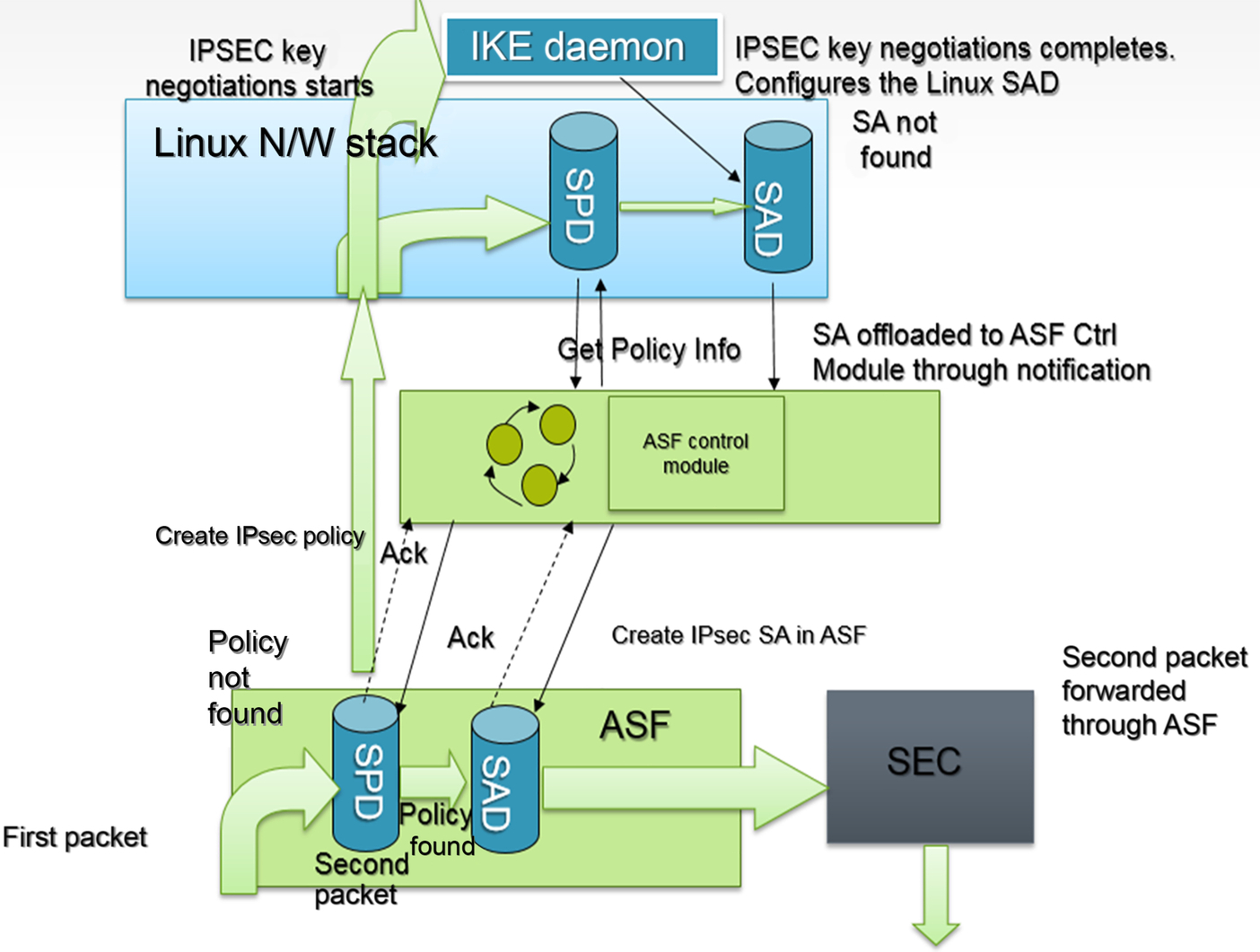
In the above diagram, when the first packet enters the system there is no policy in the ASF SPD table and the packet is given to the Linux network stack to fetch information about this flow. In this case the packet undergoes some security transformation, it triggers the IKE process to set up the SAs used for this flow. Whenever there is an update in the Linux XFRM security database, the notification comes to the ASF which in turn triggers the addition of the flow to the ASF database. Once the flow entry is created all incoming traffic is handled by the ASF without any intervention of Linux. Whenever there is a soft lifetime expiry of the configured SA, a notification is given to the Linux network stack which starts fetching new SAs. These new SAs are eventually configured in the ASF to be used for incoming traffic. Such a lightweight implementation usually gives a multifold increase in IPsec throughput compared with native Linux IPsec processing, depending upon the packet size.
Another such implementation recently added to Linux is XDP. The next section provides an overview of XDP.
5.5 eXpress Data Path (XDP) for Linux
XDP, popularly known as eXpress Data Path, has been a recent addition to the Linux kernel, facilitated by the Linux community. Initially, there were doubts and concerns about adding this to the mainline kernel, however, after lengthy discussion it was agreed to include it within Linux. This section provides a high-level overview of XDP. Most of the information included here is available online—this is an open-source utility which is part of the Linux kernel. This has been developed as a part of the IO Visor Project (details about the project are available at https://www.iovisor.org/technology/xdp).
To start, let's discuss what is behind the motivation for having such a solution added to Linux. In Linux, the network packet processing path has a significant overhead due to the generic nature of the software. In the general network packet processing path of Linux, when the packet enters a system it needs to be attached to a sk_buff which is a core entity traversing various layers of network stack before deciding on the fate of the packet—either to hand it over to some user space application, forward it, either as it is or post some transformation, or discard it, depending on system configuration. Due to all such overheads, the overall performance of the network data path is very slow when using a vanilla network stack. However, most of the time this repeated processing is not required for all the frames of a particular flow. There have been demonstrations by various implementations that the performance of the network data path can be enhanced significantly, as measured against standard Linux network performance. One such implementation is covered in the previous section under the Application-Specific Fastpath. However, there are other implementations in user space as well, like DPDK, which show that network packet performance can be enhanced multifold compared with standard Linux. All these different implementations triggered a need to have an implementation which can demonstrate good performance with Linux network stack.
XDP is a specialized programmable application that can deliver high performance for networking workloads in the Linux network data path. It introduces hooks in the software stack at the lowest level, basically the Ethernet driver level, to pull packets. These packets are processed in the XDP instead of being given to the Linux network stack. Due to such a design, there is no need to create an sk_buff and complete network stack processing can be avoided. The figure below (extracted from: https://www.iovisor.org/technology/xdp) is a high-level overview of XDP architecture.

Since, XDP extracts the frame at an almost bare-metal level it is ideal for speed benchmarking without compromising programmability. Also, adding new features will not impact the existing packet flow of the Linux kernel. Another benefit is that it is not disintegrated fully from the Linux network data path, meaning that on a need basis it can either handle the packet independently or can enqueue the packet to the Linux network stack. It is also not a replacement for the existing TCP/IP stack but rather is an augmentation to the existing stack, working in concert. It also utilizes various performance techniques, such as lockless and batched I/O operations, busy polling, direct queue accesses, page recycling to avoid overhead of allocation and freeing up, avoiding overhead of sk_buff maintenance, optimization of lookups of flow state tables, packet steering, flow hashing, and NIC off-loads. The NICs are expected to have multiple queues, support for common offloads like checksum offloads, TSO and RSS to name a few. To avoid locking, it assigns one CPU to each NIC RX queue and can work in either busy polling mode or interrupt mode. The packet processing for XDP is usually done by the BPF program which parses the packets, does lookups, and performs packet transformations. This will return the action to be taken on such frames.
Now that a high-level overview of two different implementations has been shared, the user is advised to try to benchmark the system with XDP and without XDP for the IP forward use case. While setting up the IP forward use case, the expectation is to configure the packet streams destined to be forwarded from one network port to another and look for differences between the two use cases.
5.6 General Techniques for a Better Performance Using Efficient Resource Utilization
Apart from the techniques mentioned above there are also generic techniques which improve resource utilization and eventually overall system performance. The most widely used concept in this domain is RSS, popularly known as Receive Side Scaling. This concept ensures that the multiple packet processing queues in the system get evenly loaded, based on some distribution attribute, and eventually processed by multiple CPUs. This helps in distributing the packet processing load evenly across multiple CPUs. However, this solution only works well when there are many flows leading to an even distribution across cores. In the case that there is only a single stream of data, the RSS will be unable to distribute traffic evenly across multiple cores.
There is another concept called RPS (Receive Packet Steering) which is generally implemented in the software. This has multiple advantages, including that its usability is hardware independent and that it helps in adding software filters, giving flexibility for filtering packets in terms of a variety of parameters. This method primarily relies on interprocessor interrupts to distribute traffic. RPS is beneficial in cases where the number of queues is less than the number of available CPUs and when the CPUs involved in packet processing belong to the same domain.
There is another similar concept called an RFS (Receive Flow Steering) which again is mostly implemented in the software. This allows traffic coming to a particular core to be steered away to another core running the required application for processing incoming traffic, thereby helping distribute traffic across various cores. With the help of RFS, the processing of even a single stream of data traffic occurs on multiple cores.
Apart from the techniques mentioned above, software programmers need to ensure that the code they write is highly optimized and uses cache in an optimal way to ensure minimal cache misses during packet processing. The idea is to exploit spatial locality to the fullest to avoid cache misses as much as possible. The following example shows how to rewrite code to have better spatial locality and thus a smaller number of cache misses, eventually leading to better performance.
Example
This example shows how adding the array elements in two different ways can lead to different behavior with respect to cache utilization. In C, arrays are allocated in row-major order which means each row element is contiguous. This means if each element of a column for a particular row is accessed it uses its spatial locality advantage leading to fewer cache misses compared with the case where the elements are accessed in reverse. The following figure captures data from the cache miss for the abovementioned use cases, considering that the block size is 4 bytes. From the diagram it can be deduced that the miss rate changes significantly because of the way elements in an array are accessed.

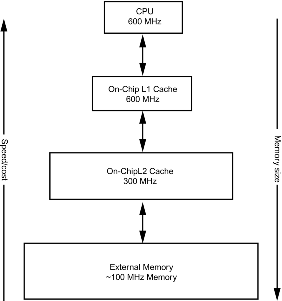
Another aspect to keep in mind while planning optimal usage of memory is that cache sizes are usually limited. Moreover, the closer the memory is to the CPU the better speed it provides, however, the costlier it will be. The following diagram captures details about different aspects like speed versus cost and the standard supported sizes of memory at different distances from the core. So, it is very challenging to optimize code such that the critical and most frequently used code resides in the L1 cache most of the time, for best performance.
6 Case Studies: Covering Microcontrollers to Network Processors
6.1 IoT Subsystem
The Internet of Things (IoT) was initially coined in a Finnish article (https://en.wikipedia.org/wiki/Internet_of_things#cite_note-TIEKE-28) as “... an information system infrastructure for implementing smart, connected objects.” With an exponential increase in number of sensors, packaged well enough to be plug-and-play and with integrated networking, IoT as a technology is rapidly gaining popularity. There has always been a requirement to connect with sensors and consider the information they provide—as far as back the early 1900s, large railway signaling systems were commissioned across the United Kingdom. However, the need to assimilate data to make smarter decisions is a new phenomenon, not possible in the past because of a lack of data processing points.
Initially, sensors were stand-alone devices—a temperature sensor would provide discrete data about temperatures at specific locations. Such a sensor required human intervention to be read, and its data needed to be copied over manually to other machines in order that they could make decisions. For example, let us consider a large power house using steam for power generation. Turbines and steam boilers are two of many important systems, which have inherent linkage—steam boiler output is input to turbines. As long ago as 1950s, enough sensors were available to capture data from various points across the boiler and turbine. But, it required human intervention to read and make logical decisions on that data. Based on steam output, turbine input was manually regulated.
Then, with the use of microcontrollers, one was finally able to connect directly to data, and data could be directly connected to other devices. For example, microcontrollers meant that smart decisions could be made about whether boilers were underheating or overheating and consequently make decisions about releasing excess steam. Microcontrollers read data from temperature sensors and made sense of whether servo motors, attached to boiler valves, should be opened or closed. All this was possible because microcontrollers could make sense of larger sets of data, beyond what simple temperature sensors could handle, and then find a correlation before producing another set of data on which an action could be based.
Multiple microcontrollers could be chained to create a workflow based on this stream of data. Once advancements in memory and SoC were achieved, it became possible to create larger streams to make better or “smarter” decisions. Thus completely automated power stations became a contemporary reality—one in which millions of sensors could feed their discrete data into an array of controllers which in turn could cascade into another set of controllers leading to an output interpreted as processed data or information worthy of decision making.
Power plants, like the steam turbine example used above, are capital intensive industries where enough capital is available for standalone research for sensors and their interaction to gradually move towards automation. Such research over the years moved them towards earliest example of “IoT Networks.” Closer to home, cars too have been through a drastic transition over the past few decades. Automotive domains were always a focal point for combustion technology in terms of generating power—almost everything else represented a mechanical engineering achievement. However, with a network of sensors and controller arrays, it is now possible to set aside the mechanical engineering marvel that is the car, and shift our focus to make it a device with which humans can interact on a daily basis through smarter decisions, making travelling more efficient and safe.
Presently, cars are huge compute nodes—processing millions of sensor inputs across their infrastructures, making critical decisions about braking, and less critical decisions about specific climate controls for users. In fact, networks of sensors expand well beyond the physical zone that is the car. Cars now interact with various surrounding infrastructure items such as other cars or even buildings and fixtures. With enough processing power, a car should eventually be able to understand road conditions by sensing the presence of all other traffic. A car should be able to communicate with a traffic light and decide to reduce its engine output for a specific duration to conserve fuel. It should also be possible for a car to interact with fixtures like building to understand the density of incoming traffic at a blind turn or crossing. It should also be possible for a car to understanding the traffic or environmental conditions that lie ahead on its journey—snow, rain, and air temperature—by communicating with cars coming from that direction, having previously encountered those conditions.
6.1.1 Choosing the Right Device
The present-day market has numerous devices spanning use cases from homes to industrial plants. However, when it comes to choosing the right device, or SoC, various factors come into play, such as compute power, power consumption, peripherals that can be mounted, form factor, and connectivity options. Based on use case, it is important to define the values of each parameter before choosing a prototyping and eventual product device. Ease of programmability is another criterion which helps reduce time to market.
For the purpose of this case study, an NXP i.MX 1060 RT SoC package was chosen. This SoC is a microcontroller platform based on an ARM Cortex M7 core, having the capability to run real-time loads (if backed by adequate OS capabilities). Being a microcontroller board has advantages and disadvantages—the primary advantage being that it has a lower cost than microprocessor-based SoC packages; the primary disadvantage being that it has limited support for generic application stacks. The i.MX 1060 RT can offer a significant number of applications—being a real-time board, it is a platform capable of controlling devices such as industrial robots or servo motors. Having a low power consumption means that it can be used as an edge device for “always on” use cases. NXP MCUXpresso IDE provides an easy and convenient way to enable the board and deploy applications in the least possible time.
Another processor chosen was the LS1012, which is a low-end ARM-based network processor from NXP. This SoC is a low power communication processor offered under the LayerScape QorIQ family of ARM-based processors. It uses a single ARM Cortex A53 core which can be clocked as high as 1 GHz, with a hardware packet forwarding engine and high-speed interfaces to deliver line-rate networking performance in an ultrasmall size envelope with a typical power dissipation of 1 W.
In this use case the standard release code from SDK was used without doing any local optimizations and the same workload was offered to both SoCs. Their performances were measured. The workload was an IPERF client/server application running a performance benchmark for a TCP use case.
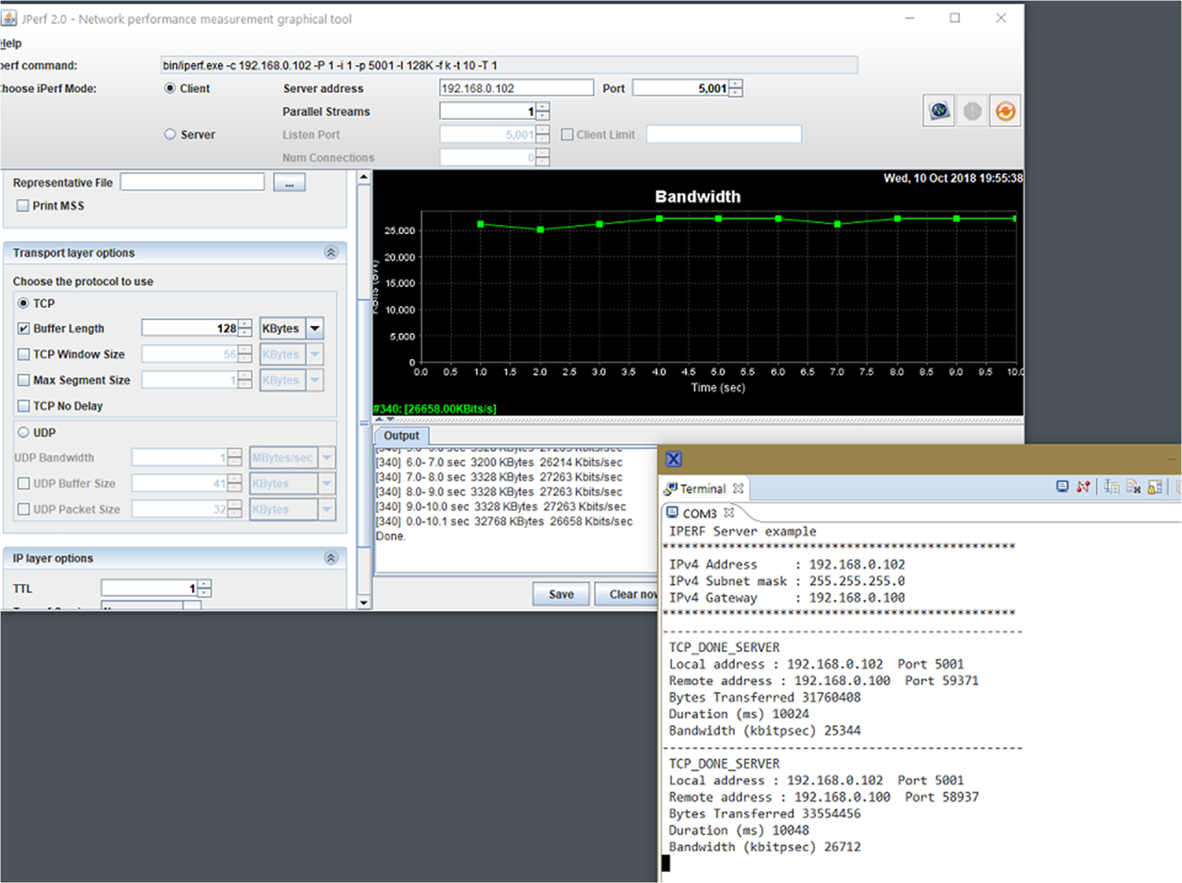
First, the data was shared with the i.MX 1060RT SoC running at 600 MHz. The snapshot below captures the data which clearly shows that the maximum performance achieved for an iperf application offering the TCP workload is around 27 Mbps on the i.MX RT1060. Please note that the performance measurement was done for the stock released code for the SOC without any local changes being made to it. Performance improvement or degradation may occur if changes are made to the code.
The same workload was run on the LS1012 network processor running at 1 GHz. This SoC was able to saturate the 1-Gbps link with ease.

To conclude, theoretically speaking if the frequency of the i.MX 1060RT was clocked to 1 GHz, it should be able to deliver a performance of around 41 Mbps, which is still much lower than the performance that can be achieved on the LS1012 platform. Hence, it can be deduced that core frequency cannot be used as a benchmark when deciding which SoC to use for a particular use case. It can be seen from the above case study that even though both the processors are ARM-based low-cost/power products, if the requirement is to design a networking product which can deliver high networking performance with low cost then the LS1012 is preferable to the i.MX Rt1060. However, if the use case requires networking capabilities along with other capabilities like connectivity with external sensors in order to collect data along with an interface to connect to external input devices like a camera with a real-time processing capability, then the i.MX RT would be the obvious choice.
Exercises
Please create programs for the following problem statements:
- 1. Create two namespaces, net_ns1 and net_ns2. Configure the system to allow forwarding of packets from one namespace to another.
- 2. Design a packet sniffer which sniffs all packets coming on a network device.
- 3. Design a packet sniffer using raw sockets which will sniff packets for a particular vlan on a network device. Assume that there are three vlans configured on eth0, namely, eth0.10, eth0.20, and eth0.30. Write a sniffer using raw sockets to capture the packets coming on eth0.20.
- 4. Write a program to print the state change of an NF_CONTRACK entry. The program shall print the details of the entry created, deleted, or updated for each flow.