
Chapter 12
Lines and interconnection
This chapter is concerned with the interconnection of analogue audio signals, and the solving of problems concerned with analogue interfacing. It is not intended to cover digital interfacing systems here, since this subject is adequately covered in Chapter 10. The proper interconnection of analogue audio signals, and an understanding of the principles of balanced and unbalanced lines, is vital to the maintenance of high quality in an audio system, and will remain important for many years notwithstanding the growing usage of digital systems.
Transformers
Mains transformers are widely used throughout the electrical and electronics industries, usually to convert the 240 V AC mains voltage to a rather lower voltage. Audio transformers are widely used in audio equipment for balancing and isolating purposes, and whereas mains transformers are required only to work at 50 Hz, audio transformers must give a satisfactory performance over the complete audio spectrum. Fortunately most audio transformers are only called upon to handle a few volts at negligible power, so they are generally much smaller than their mains counterparts. The principles of transformer operation are outlined in Fact File 12.1.
Transformers and impedances
Consider Figure 12.1(a). The turns ratio is 1:2, so the square of the turns ratio (used to calculate the impedance across the secondary) is 1:4, and therefore the impedance across the secondary will be found to be 10 × 4 = 40 k. Another example is shown in Figure 12.1(b). The turns ratio is 1:4. 0.7 volts is applied across the primary and gives 2.8 volts across the secondary. The square of the turns ratio is 1:16, so the impedance across the secondary is 2 k × 16 = 32 k. The transformer also works backwards, as shown in Figure 12.1(c). A 20 k resistor is now placed across the secondary. The square of the turns ratio is 1:16, and therefore the impedance across the primary is 20 k ÷ 16 = 1k25.
Fact file 12.1 The transformer
From the diagrams it can be seen that the transformer consists of a laminated core (i.e.: a number of thin sheets of metal ‘laminated’ together to form a single thick core) around which is wound a ‘primary’ winding and a ‘secondary’ winding. If an alternating current is passed through the primary winding, magnetic flux flows in the core (in a similar fashion to the principle of the tape head; see Fact File 6.1), and thus through the secondary winding. Flux changes in the secondary winding cause a current to be induced in it. The voltage across the secondary winding compared with that across the primary is proportional to the ratio between the number of turns on each coil. For example, if the primary and secondary windings each have the same number of turns, then 1 volt across the primary will also appear as 1 volt across the secondary. If the secondary has twice the number of turns as the primary then twice the voltage will appear across it. The transformer also works in reverse – voltage applied to the secondary will be induced into the primary in proportion to the turns ratio.

The current flowing through the secondary is in inverse proportion to the turns ratio, such that equal power exists on the primary and secondary sides of the transformer (it is not magic – the increased voltage across the secondary of a step-up transformer is traded off against reduced current!).
It is important to remember that the principle of operation of the transformer depends on AC in the windings inducing an alternating field into the core (i.e.: it is the change in direction of magnetic flux which induces a current in the secondary, not simply the presence of constant flux). A DC signal, therefore, is not passed by a transformer.
Impedances are proportional to the square of the turns ratio, as discussed in the main text. A transformer will ‘reflect’ the impedances between which it works. In the case of a 1:1 transformer the impedance across the secondary is equal to the impedance across the primary, but in the case of a 1:2 transformer the impedance seen across the secondary would be four times that across the primary.

Figure 12.1 Examples of transformer circuits. (a) What is the impedance across the secondary? (b) What are the impedance and voltage across the secondary? (c) What is the impedance across the primary?

Figure 12.2 The input impedance of the mixer is seen by the microphone, modified by the turns ratio of the transformer, and vice versa
Consider now a microphone transformer that is loaded with an impedance on both sides, as shown in Figure 12.2. The transformer presents the 2 k impedance of the mixer to the microphone, and the 200 ohm impedance of the microphone to the mixer. With a step-up ratio of 1:4 the square of the turns ratio would be 1:16. The microphone would be presented with an impedance of 2 k ÷ 16 = 125 ohms, whereas the mixer would be presented with an impedance of 200 × 16 = 3200 ohms. In this particular case a 1:4 step-up transformer is unsuitable because microphones like to work into an impedance five times or more their own impedance, so 125 ohms is far too low. Similarly, electronic inputs work best when driven by an impedance considerably lower than their own, so 3200 ohms is far too high.
Limitations of transformers
Earlier it was mentioned that an audio transformer must be able to handle the complete audio range. At very high and very low frequencies this is not easy to achieve, and it is usual to find that distortion rises at low frequencies, and also to a lesser extent at very high frequencies. The frequency response falls away at the frequency extremes, and an average transformer may well be 3 dB down at 20 Hz and 20 kHz compared with mid frequencies. Good (= expensive) transformers have a much better performance than this. All transformers are designed to work within certain limits of voltage and current, and if too high a voltage is applied a rapid increase in distortion results.
The frequency response and distortion performance is affected by the impedances between which the transformer works, and any particular model will be designed to give its optimum performance when used for its intended application. For example, a microphone transformer is designed to handle voltages in the millivolt range up to around 800 mV or so. The primary winding will be terminated with about 200 ohms, and the secondary will be terminated with around 1–2 k (or rather more if a step-up ratio is present). A line level transformer on the other hand must handle voltages up to 8 volts or so, and will probably be driven by a source impedance of below 100 ohms, and will feed an impedance of 10 k or more. Such differing parameters as these require specialised designs. There is no ‘universal’ transformer.
Transformers are sensitive to electromagnetic fields, and so their siting must be given consideration. Place an audio transformer next to a mains transformer and hum will be induced into it, and thus into the rest of the audio circuit. Most audio transformers are built into metal screening cans which considerably reduce their susceptibility to radio-frequency interference and the like.
Unbalanced lines
‘Unbalanced’ in this context does not mean unstable or faulty. The unbalanced audio line is to be found in virtually all domestic audio equipment, much semiprofessional and some professional audio equipment as well. It consists of a ‘send’ and ‘return’ path for the audio signal, the return path being an outer screening braid which encloses the send wire and screens it from electromagnetic interference, shown in Figure 12.3. The screening effect considerably reduces interference such as hum, RF, and other induction, without eliminating it entirely. If the unbalanced line is used to carry an audio signal over tens of metres, the cumulative effect of interference may be unacceptable. Earth loops can also be formed (see Fact File 12.2). Unbalanced lines are normally terminated in connectors such as phono plugs, DIN plugs and quarter-inch ‘A-gauge’ jack plugs.
An improved means of unbalanced interconnection is shown in Figure 12.4. The connecting lead now has two wires inside the outer screen. One is used as the signal wire, and instead of the return being provided by the outer screen, it is provided by the second inner wire. The screening braid is connected to earth at one end only, and so it merely provides an interference screen without affecting the audio signal.
Cable effects with unbalanced lines
Cable resistance
‘Loop’ resistance is the total resistance of both the send and return paths for the signal, and generally, as long as the loop resistance of a cable is a couple of orders of magnitude (i.e.: a factor of 100) lower than the input impedance of the equipment it is feeding, it can be ignored. For example, the output impedance of a tape recorder might be 200 ohms. The input impedance of the amplifier it would be connected to would normally be 10 k or more. The DC resistance of a few metres of connecting cable would only be a fraction of an ohm and so would not need to be considered. But what about 100 metres of microphone cable? The input impedance of a microphone amplifier would normally be at least 1000 ohms. Two orders of magnitude lower than this is 10 ohms. Even 100 metres of mic lead will have a lower resistance than this unless very thin cheap wire is used, and so again the DC resistance of microphone cables can be ignored.

Figure 12.3 Simple unbalanced interconnection
Fact file 12.2 Earth loops
It is possible to wire cables such that the screening braid of a line is connected to earth at both ends. In many pieces of audio equipment the earth side of the audio circuit is connected to the mains earth. When two or more pieces of equipment are connected together this creates multiple paths to the mains earth, and low-level mains currents can circulate around the screening braids of the connecting leads if the earths are at even slightly different potentials. This induces 50 Hz mains hum into the inner conductor. A common remedy for this problem is to disconnect the earth wires in the mains plugs on all the interconnected pieces of equipment except one, the remaining connection providing the earth for all the other pieces of equipment via the audio screening braids. This, though, is potentially dangerous, since if a piece of equipment develops a fault and the mains plug with the earth connection is unplugged, then the rest of the system is now unearthed and the fault could in serious cases place a mains voltage on the metal parts of the equipment. A lot of units are now ‘double insulated’, so that internal mains wiring cannot place mains voltage on the metal chassis. The mains lead is just two core, live and neutral.
Speaker cables do need to be watched, because the input impedance of loudspeakers is of the order of 8 ohms. Wiring manufacturers quote the value of DC resistance per unit length (usually 1 metre) of cable, and a typical cable suitable for speaker use would be of 6 amp rating and about 12 milliohms (0.012 ohms) resistance per metre. Consider a 5 metre length of speaker cable. Its total loop resistance then would be 10 metres multiplied by 0.012 ohms = 0.12 ohms. This is a bit too high to meet the criterion stated above, an 8 ohm speaker requiring a cable of around 0.08 ohm loop resistance. In practice, though, this would probably be perfectly adequate, since there are many other factors which will affect sound quality. Nevertheless, it does illustrate that quite heavy cables are required to feed speakers, otherwise too much power will be wasted in the cable itself before the signal reaches the speaker.
If the same cable as above were used for a 40 m feed to a remote 8 ohm loudspeaker, the loop resistance would be nearly 1 ohm and nearly one-eighth of the amplifier power would be dissipated in heat in the cable. The moral here is to use the shortest length of cable as is practicable, or if long runs are required use the 100 volt line system (see ‘100 volt lines’, below).

Figure 12.4 Alternative unbalanced interconnection
Cable and transformer inductance
The effect of cable inductance (see ‘Sound in electrical form’, Chapter 1) becomes more serious at high frequencies, but at audio frequencies it is insignificant even over long runs of cable. Conversely, inductance is extremely important in transformers. The coils on the transformer cores consist of a large number of turns of wire, and the electromagnetic field of each turn works against the fields of the other turns. The metallic core greatly enhances this effect. Therefore, the inductance of each transformer coil is very high and presents a high impedance to an audio signal. For a given frequency, the higher the inductance the higher the impedance in ohms.
Cable capacitance
The closer the conductors in a cable are together, the greater the capacitance (see ‘Sound in electrical form’, Chapter 1). The surface area of the conductors is also important. Capacitance is the opposite of inductance in that, for a given frequency, the greater the capacitance the lower is the impedance in ohms. In a screened cable the screening braid entirely encloses the inner conductor and so the surface area of the braid, as seen by this inner conductor, is quite large. Since large surface area implies high-capacitance, screened cable has a much higher capacitance than ordinary mains wiring, for example. So when an audio signal looks into a connecting cable it sees the capacitance between the conductors and therefore a rather less-than-infinite impedance between them, especially at high frequencies. A small amount of the signal can therefore be conducted to earth via the screen.
In the diagram in Figure 12.5 there are two resistors of equal value. A voltage V1 is applied across the two. Because the value of the resistors is the same, V1 is divided exactly in half, and V2 will be found to be exactly half the value of V1. If the lower resistor were to be increased in value to 400 ohms then twice the voltage would appear across it than across the upper resistor. The ratio of the resistors equals the ratio of the voltages across them.
Consider a 200 ohm microphone looking into a mic lead, as shown in Figure 12.6(a). C is the capacitance between the screening braid and the inner core of the cable. The equivalent of this circuit is shown in Figure 12.6(b). Manufacturers quote the capacitance of cables in picofarads (pF) per unit length. A typical value for screened cable is 200 pF (0.0002 μF) per metre. A simple formula exists for determining the frequency at which 3 dB of signal is lost for a given capacitance and source resistance:

Figure 12.5 The voltage V2 across the output is half the input voltage (V1)

Figure 12.6 (a) A microphone with a 200 ohm output impedance is connected to an amplifier. (b) Lead capacitance conducts high frequencies to ground more than low frequencies, and thus the cable introduces HF roll-off. V2 is lower at HF than at LF
f = 159 155/RC
where f = frequency in hertz (Hz), R = resistance in ohms, and C = capacitance in microfarads (μF).
To calculate the capacitance which will cause a 3 dB loss at 40 kHz, putting it safely out of the way of the audio band, the formula must be rearranged to give the maximum value of acceptable capacitance:
C = 159 155/Rf
Thus, if R = 200 (mic impedance), f = 40 000:
C = 159 155 ÷ (200 × 40 000) ≈ 0.02 μF
So a maximum value of 0.02 μF of lead capacitance is acceptable for a mic lead. Typical lead capacitance was quoted as 0.0002 μF per metre, so 100 metres will give 0.02 μF, which is the calculated acceptable value. Therefore one could safely use up to 100 metres of typical mic cable with a standard 200 ohm microphone without incurring significant signal loss at high frequencies.
The principle applies equally to other audio circuits, and one more example will be worked out. A certain tape recorder has an output impedance of 1 k. How long a cable can it safely drive? From the above formula:
C = 159 155 ÷ (1000 × 40 000) ≈ 0.004 μF
In this case, assuming the same cable capacitance, the maximum safe cable length is 0.004 ÷ 0.0002 = 20 metres. In practice, modern audio equipment generally has a low enough source impedance to drive long leads, but it is always wise to check up on this in the manufacturer’s specification. Probably of greater concern will be the need to avoid long runs of unbalanced cable due to interference problems.
Balanced lines
The balanced line is better at rejecting interference than the unbalanced line, and improvements upon the performance of the unbalanced line in this respect can be 80 dB or more for high-quality microphone lines.
As shown in Figure 12.7, the connecting cable consists of a pair of inner conductors enclosed by a screening braid. At each end of the line is a ‘balancing’ transformer. The output amplifier feeds the primary of the output transformer and its voltage appears across the secondary. The send and return paths for the audio signal are provided by the two inner conductors, and the screen does not form part of the audio circuit. If an interference signal breaks through the screen it is induced equally into both signal lines. At the secondary transformer’s primary the induced interference current, flowing in the same direction in both legs of the balanced line, cancels out, thus rejecting the interference signal. Two identical signals, flowing in opposite directions, cancel out where they collide.
Such an interfering signal is called a ‘common mode’ signal because it is equal and common to both audio lines. The rejection of this in the transformer is termed ‘common mode rejection’ (CMR). A common mode rejection ratio (CMRR) of at least 80 dB may be feasible. Meanwhile, the legitimate audio signal flows through the primary of the transformer as before, because the signal appears at each end of the coil with equal strength but opposite phase. Such a signal is called a ‘differential signal’, and the balanced input is also termed a ‘differential input’ because it accepts differential mode signals but rejects common mode signals.
So balanced lines are used for professional audio connections because of their greatly superior rejection of interference, and this is particularly useful when sending just a few precious millivolts from a microphone down many metres of cable to an amplifier.

Figure 12.7 A balanced interconnection using transformers
Working with balanced lines
In order to avoid earth loops (see Fact File 12.2) with the balanced line, the earth screen is often connected at one end only, as shown in Figure 12.8(a), and still acts as a screen for the balanced audio lines. There is now no earth link between the two pieces of equipment, and so both can be safely earthed at the mains without causing an earth loop. The transformers have ‘isolated’ the two pieces of equipment from each other. The one potential danger with this is that the connecting lead with its earth disconnected in the plug at one end may later be used as a microphone cable. The lack of earth continuity between microphone and amplifier will cause inadequate screening of the microphone, and will also prevent a phantom power circuit being made (see ‘Microphone powering options’, Chapter 3), so such cables and tie-lines should be marked ‘earth off’ at the plug without the earth connection.
Unfortunately, not all pieces of audio equipment have balanced inputs and outputs, and one may be faced with the problem of interfacing a balanced output with an unbalanced input, and an unbalanced output with a balanced input. A solution is shown in Figure 12.8(b), were the output transformer is connected to the signal and earth of the unbalanced input to give signal continuity. Because the input is unbalanced, there is no common mode rejection and the line is as susceptible to interference as an ordinary unbalanced line is. But notice that the screen is connected at one end only, so at least one can avoid an earth loop.
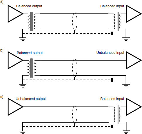
Figure 12.8 (a) Balanced output to balanced input with screen connected to earth only at output. (b) Balanced output to unbalanced input. (c) Unbalanced output to balanced input
Figure 12.8(c) illustrates an unbalanced output feeding a balanced input. The signal and earth from the output feed the primary of the input transformer. Again the screen is not connected at one end so earth loops are avoided. Common mode rejection of interference at the input is again lost, because one side of the transformer primary is connected to earth. A better solution is to use a balancing transformer as close to the unbalanced output as possible, preferably before sending the signal over any length of cable. In the longer term it would be a good idea to fit balancing transformers inside unbalanced equipment with associated three-pin XLR-type sockets (see Fact File 12.3) if space inside the casing will allow. (Wait until the guarantee has elapsed first!)
Star-quad cable
Two audio lines can never occupy exactly the same physical space, and any interference induced into a balanced line may be slightly stronger in one line than in the other. This imbalance is seen by the transformer as a small differential signal which it will pass on, so a small amount of the unwanted signal will still get through. To help combat this, the two audio lines are twisted together during manufacture so as to present, on average, an equal face to the interference along both lines. A further step has been taken in the form of a cable called ‘star-quad’. Here, four audio lines are incorporated inside the screen, as shown in Figure 12.9.
Fact file 12.3 XLR-3 connectors
The most common balanced connector in professional audio is the XLR-3. This connector has three pins (as shown in the diagram), carrying respectively:
Pin 1 Screen
Pin 2 Signal (Live or ‘hot’)
Pin 3 Signal (Return or ‘cold’)

It is easy to remember this configuration, since X–L–R stands for Xternal, Live, Return. Unfortunately, an American convention still hangs on in some equipment which reverses the roles of pins 2 and 3, making pin 2 return and pin 3 live (or ‘hot’). The result of this is an apparent absolute phase reversal in signals from devices using this convention when compared with an identical signal leaving a standard device. Modern American equipment mostly uses the European convention, and American manufacturers have now agreed to standardise on this approach.

Figure 12.9 Four conductors are used in star-quad cable
It is connected as follows. The screen is connected as usual. The four inner cores are connected in pairs such that two of the opposite wires (top and bottom in the figure) are connected together and used as one line, and the other two opposite wires are used as the other. All four are twisted together along the length of the cable during manufacture. This configuration ensures that for a given length of cable, both audio lines are exposed to an interference signal as equally as possible so that any interference is induced as equally as possible. So the input transformer sees the interference as a virtually perfect common mode signal, and efficiently rejects it. This may seem like taking things to extremes, but star-quad is in fact quite widely used for microphone cables. When multicore cables are used which contain many separate audio lines in a single thick cable, the balanced system gives good immunity from crosstalk, due to the fact that a signal in a particular wire will be induced equally into the audio pair of the adjacent line, and will therefore be a common mode signal. Star-quad multicores give even lower values of crosstalk.
Electronic balancing
Much audio equipment uses an electronically balanced arrangement instead of a transformer, and it is schematically represented as in Figure 12.10. The transformers have been replaced by a differential amplifier. The differential amplifier is designed to respond only to differential signals, as is the case with the transformer, and has one positive and one negative input. Electronically balanced and transformer-balanced equipment can of course be freely intermixed. Reasons for dispensing with transformers include lower cost (a good transformer is rather more expensive than the electronic components which replace it), smaller size (transformers take up at least a few cubic centimetres, the alternative electronics rather less), less susceptibility to electromagnetic interference, and rather less sensitivity to the impedances between which they work with respect to distortion, frequency response and the like.

Figure 12.10 An electronically balanced interconnection using differential amplifiers
Good electronic balancing circuitry is, however, tricky to design, and the use of high-quality transformers in expensive audio equipment may well be a safer bet than electronic balancing of unknown performance. The best electronic balancing is usually capable of equal CMR performance to the transformer. Critics of transformer balancing cite factors such as the low-frequency distortion performance of a transformer, and its inability to pass extremely low frequencies, whereas critics of electronic balancing cite the better CMR available from a transformer when compared with a differential amplifier, and the fact that only the transformer provides true isolation between devices. Broadcasters often prefer to use transformer balancing because signals are transferred over very long distances and isolation is required, whereas recording studios often prefer electronic balancing, claiming that the sound quality is better.
100 volt lines
Principles
In ‘Cable resistance’, above, it was suggested that the resistance of even quite thick cables was still sufficient to cause signal loss in loudspeaker interconnection unless short runs were employed. But long speaker lines are frequently unavoidable, examples being: back-stage paging and show relay speakers in theatres; wall-mounted speakers in lecture theatres and halls; paging speakers in supermarkets and factories; and open-air ‘tannoy’ horns at fairgrounds and fêtes. All these require long speaker runs, or alternatively a separate power amplifier sited close to each speaker, each amplifier being driven from the line output of a mixer or microphone amplifier. The latter solution will in most cases be considered an unnecessarily expensive and complicated solution. So the ‘100 volt line’ was developed so that long speaker cable runs could be employed without too much signal loss along them.
The problem in normal speaker connection is that the speaker cable has a resistance comparable with, or even greater than, the speaker’s impedance over longer runs. It was shown in ‘limitations of transformers’, above, that a transformer reflects impedance according to the square of the turns ratio. Suppose a transformer with a turns ratio of 5:1 is connected to the input of an 8 ohm speaker, as shown in Figure 12.11. The square of the turns ratio is 25:1 so the impedance across the primary of the transformer is 25 × 8 = 200 ohms. Now, the effective impedance of the speaker is much greater than the cable resistance, so most of the voltage will now reach the primary of the transformer and thence to the secondary and the speaker itself. But the transformer also transforms voltage, and the voltage across the secondary will only be a fifth of that across the primary. To produce 20 volts across the speaker then, one must apply 100 volts to the primary.

Figure 12.11 Transformer coupling to a loudspeaker as used in 100 volt line systems
In a 100 V line system, as shown in Figure 12.12, a 50 W power amplifier drives a transformer with a step-up ratio of 1:5. Because the output impedance of a power amplifier is designed to be extremely low, the impedance across the secondary is also low enough to be ignored. The 20 volts, 2.5 amp output of the 50 watt amplifier is stepped up to 100 volts. The current is correspondingly stepped down to 0.5 amps (see Fact File 12.1), so that the total power remains the same. Along the speaker line there is a much higher voltage than before, and a much lower current. The voltage drop across the cable resistance is proportional to the current flowing through it, so this reduction in current means that there is a much smaller voltage drop due to the line. At the speaker end, a transformer restores the voltage to 20 volts and the current to 2.5 amps, and so the original 50 watts is delivered to the speaker.
A 50 watt amplifier has been used in the discussion. Any wattage of amplifier can be used, the transformer being chosen so that the step-up ratio gives the standard 100 volts output when the amplifier is delivering its maximum power output. For example, an amplifier rated at 100 watts into 8 ohms produces about 28 V. The step-up ratio of the line transformer would then have to be 28:100, or 1:3.6, to give the standard 100 volt output when the amplifier is being fully driven.
Returning to the loudspeaker end of the circuit. What if the speaker is only rated at 10 watts? The full 100 watts of the above amplifier would burn it out very quickly, and so a step-down ratio of the speaker transformer is chosen so that it receives only 10 watts. As 10 watts across 8 ohms is equivalent to around 9 volts, the required speaker transformer would have a step-down ratio of 100:9, or approximately 11:1.
Working with 100 V lines
Speaker line transformers usually have a range of terminals labelled such that the primary side has a choice of wattage settings (e.g.: 30 W, 20 W, 10 W, 2 W) and the secondary gives a choice of speaker impedance, usually 15 ohms, 8 ohms and 4 ohms. This choice means that a number of speaker systems can be connected along the line (a transformer being required for each speaker enclosure), the wattage setting being appropriate to the speaker’s coverage. For example, a paging system in the back-stage area of a theatre could be required to feed paging to six dressing rooms, a large toilet, and a fairly noisy green room. The dressing rooms are small and quiet, and so small speakers rated at 10 watts are employed with line transformers wired for 2 watts output. The large toilet requires greater power from the speaker, so one could use a 10 W speaker with a line transformer wired for 10 W output. The noisy green room could have a rather larger 20 W speaker with a line transformer wired for 20 W output. In this way, each speaker is supplied only with the wattage required to make it loud enough to be clearly heard in that particular room. A 20 watt speaker in a small dressing room would be far too loud, and a 2 watt speaker in a larger, noisier room would be inadequate.

Figure 12.12 Voltage/current relationships in an example of 100 volt line operation
As a string of loudspeakers is added to the system, one must be careful that the total wattage of the speakers does not exceed the output wattage of the power amplifier, or the latter will be overloaded. In the example, the six dressing rooms were allocated 2 W each, total 12 W. The toilet was allocated 10 W, the green room 20 W. The total is therefore 42 W, and a 50 W amplifier and line transformer would be adequate. In practice, a 100 W amplifier would be chosen to allow for both a good safety margin and plenty of power in hand if extra speakers need to be connected at a later date.
From the foregoing, it might well be asked why the 100 volt line system is not automatically used in all speaker systems. One reason is that 100 volts is high enough to give an electric shock and so is potentially dangerous in the domestic environment and other places where members of the public could interfere with an inadequately installed system. Secondly, the ultimate sound quality is compromised by the presence of transformers in the speaker lines – they are harder to design than the microphone and line level transformers already discussed, because they have to handle high voltages as well as several amps – and whereas they still give a perfectly adequate and extremely useful performance in paging and background music applications, they are not therefore used in highquality PA systems or hi-fi and studio monitor speakers.
600 ohms
One frequently sees 600 ohms mentioned in the specifications of mixers, microphone amplifiers, and other equipment with line level outputs. Why is 600 ohms so special? The short answer is: it is not.
Principles
As has been shown, the output impedances of audio devices are low, typically 200 ohms for microphones and the same value or rather less for line level outputs. The input impedances of devices are much higher, at least 1–2 k for microphone inputs and 10 k or more for line inputs. This is to ensure that virtually the whole of the output voltage of a piece of equipment appears across the input it is feeding. Also, lower input impedances draw a higher current for a given voltage, the obvious example of this being an 8 ohm loudspeaker which draws several amps from a power amplifier. So a high input impedance means that only very small currents need to be supplied by the outputs, and one can look upon microphone and line level signals as being purely voltage without considering current.
This works fine, unless you are a telephone company that needs to send its signals along miles of cable. Over these distances, a hitherto unmentioned parameter comes into play which would cause signal loss if not dealt with, namely the wavelength of the signal in the cable. Now the audio signal is transmitted along a line at close to the speed of light (186 000 miles per second or 3 × 10⁸ metres per second). The shortest signal wavelength will occur at the upper limit of the audio spectrum, and will be around 9.3 miles (14.9 km) at 20 kHz.
When a cable is long enough to accommodate a whole wavelength or more, the signal can be reflected back along the line and cause some cancellation of the primary signal. Even when the cable run is somewhat less than a wavelength some reflection and cancellation still occurs. To stop this from happening the cable must be terminated correctly, to form a so-called ‘transmission line’, and input and output impedances are chosen to be equal. The value of 600 ohms was chosen many decades ago as the standard value for telecommunications, and therefore the ‘600 ohm balanced line’ is used to send audio signals along lines which need to be longer than a mile or so. It was chosen because comparatively little current needs to be supplied to drive this impedance, but on the other hand it is not high enough to allow much interference, as it is much easier for interference to affect a high-impedance circuit than a low one. Thus, professional equipment began to appear which boasted ‘600 ohms’ to make it compatible with these lines. Unfortunately, many people did not bother to find out, or never understood, why 600 ohms was sometimes needed, and assumed that this was a professional audio standard per se, rather than a telecommunications standard. It was used widely in broadcasting, which has parallels with telecommunications, and may still be found in many cases involving older equipment.
The 600 ohm standard also gave rise to the standard reference level unit of 0 dBm, which corresponds to 1 mW of power dissipated in a resistance of 600 ohms. The corresponding voltage across the 600 ohm resistance at 0 dBm is 0.775 volts, and this leads some people still to confuse dBm with dBu, but 0 dBu refers simply to 0.775 volts with no reference to power or impedance: dBu is much more appropriate in modern equipment, since, as indicated above, the current flowing in most interfaces is negligible and impedances vary; dBm should only correctly be used in 600 ohm systems, unless an alternative impedance is quoted (e.g. dBm (75 ohms) is sometimes used in video equipment where 75 ohm termination is common).
Problems with 600 ohm equipment
A 600 ohm output impedance is too high for normal applications. With 600 ohms, 200 pF per metre cable, and an acceptable 3 dB loss at 40 kHz, the maximum cable length would be only around 33 m, which is inadequate for many installations. (This HF loss does not occur with the properly terminated 600 ohm system because the cable assumes the properties of a transmission line.) Furthermore, consider a situation where a mixer with a 600 ohm output impedance is required to drive five power amplifiers, each with an input impedance of 10 k. Five lots of 10 k in parallel produce an effective impedance of 2 k, as shown in Figure 12.13(a). Effectively then 600 ohms is driving 2 k, as shown in Figure 12.13(b). If V1 is 1 volt then V2 (from Ohm’s law) is only 0.77 volts. Almost a quarter of the audio signal has been lost, and only a maximum of 33 metres of cable can be driven anyway.
Despite this, there are still one or two manufacturers who use 600 ohm impedances in order to appear ‘professional’. It actually renders their equipment less suitable for professional use, as has been shown. One specification that is frequently encountered for a line output is something like: ‘capable of delivering +20 dBu into 600 ohms’. Here +20 dBu is 7.75 volts, and 600 ohms is quite a low impedance, thus drawing more current from the source for a given voltage than, say, 10 kΩ does. The above specification is therefore useful, because it tells the user that the equipment can deliver 7.75 volts even into 600 ohms, and can therefore safely drive, say, a stack of power amplifiers, and/or a number of tape recorders, etc., without being overloaded. A domestic cassette recorder, for instance, despite having a low output impedance, could not be expected to do this. Its specification may well state ‘2 volts into 10 kΩ or greater’. This is fine for domestic applications, but one should do a quick calculation or two before asking it to drive all the power amplifiers in the building at once.

Figure 12.13 (a) Considerable signal loss can result if a 600 ohm output is connected to a number of 10 k inputs in parallel. (b) Electrical equivalent
DI boxes
Overview
A frequent requirement is the need to interface equipment that has basically nonstandard unbalanced outputs with the standard balanced inputs of mixers, either at line level or microphone level. An electric guitar, for example, has an unbalanced output of fairly high impedance – around 10 kΩ or so. The standard output socket is the ‘mono’ quarter-inch jack, and output voltage levels of around a volt or so (with the guitar’s volume controls set to maximum) can be expected. Plugging the guitar directly into the mic or line level input of a mixer is unsatisfactory for several reasons: the input impedance of the mixer will be too low for the guitar, which likes to drive impedances of 500 kΩ or more; the guitar output is unbalanced so the interference-rejecting properties of the mixer’s balanced input will be lost; the high output impedance of the guitar renders it incapable of driving long studio tie-lines; and the guitarist will frequently wish to plug the instrument into an amplifier as well as the mixer, and simply using the same guitar output to feed both via a splitter lead electrically connects the amplifier to the studio equipment which causes severe interference and low-frequency hum problems. Similar problems are encountered with other instruments such as synthesisers, electric pianos, and pickup systems for acoustic instruments.
To connect such an instrument with the mixer, a special interfacing unit known as a DI box (DI = direct injection) is therefore employed. This unit will convert the instrument’s output to a low-impedance balanced signal, and also reduce its output level to the millivolt range suitable for feeding a microphone input. In addition to the input jack socket, it will also have an output jack socket so that the instrument’s unprocessed signal can be passed to an amplifier as well. The low-impedance balanced output appears on a standard three-pin XLR panelmounted plug which can now be looked upon as the output of a microphone. An earth-lift switch is also provided which isolates the earth of the input and output jack sockets from the XLR output, to trap earth loop problems.
Passive DI boxes
The simplest DI boxes contain just a transformer, and are termed ‘passive’ because they require no power supply. Figure 12.14 shows the circuit. The transformer in this case has a 20:1 step-down ratio, converting the fairly high output of the instrument to a lower output suitable for feeding microphone lines. Impedance is converted according to the square of the turns ratio (400:1), so a typical guitar output impedance of 15 kΩ will be stepped down to about 40 ohms which is comfortably low enough to drive long microphone lines. But the guitar itself likes to look into a high impedance. If the mixer’s microphone input impedance is 2 kΩ, the transformer will step this up to 800 kΩ which is adequately high for the guitar. The ‘link output jack socket’ is used to connect the guitar to an amplifier if required. Note the configuration of the input jack socket: the make-and-break contact normally short-circuits the input which gives the box immunity from interference, and also very low noise when an instrument is not plugged in. Insertion of the jack plug opens this contact, removing the short-circuit. The transformer isolates the instrument from phantom power on the microphone line.
This type of DI box design has the advantages of being cheap, simple, and requiring no power source – there are no internal batteries to forget to change. On the other hand, its input and output impedances are entirely dependent on the reflected impedances each side of the transformer. Unusually low microphone input impedances will give insufficiently high impedances for many guitars. Also, instruments with passive volume controls can exhibit output impedances as high as 200 kΩ with the control turned down a few numbers from maximum, and this will cause too high an impedance at the output of the DI box for driving long lines. The fixed turns ratio of the transformer is not equally suited to the wide variety of instruments the DI box will encounter, although several units have additional switches which alter the transformer tapping giving different degrees of attenuation.
Active DI boxes
The active DI box replaces the transformer with an electronic circuit which presents a constant very high impedance to the instrument and provides a constant lowimpedance output. Additionally, the presence of electronics provides scope for including other features such as several switched attenuation values (say −20 dB, −40 dB, −60 dB), high and low filters and the like. The box is powered either by internal batteries, or preferably by the phantom power on the microphone line. If batteries are used, the box should include an indication of battery status; a ‘test’ switch is often included which lights an LED when the battery is good. Alternatively, an LED comes on as a warning when the voltage of the battery drops below a certain level. The make-and-break contacts of the input jack socket are often configured so that insertion of the jack plug automatically switches the unit on. One should be mindful of this because if the jack plug is left plugged into the unit overnight, for instance, this will waste battery power. Usually the current consumption of the DI box is just a few milliamps, so the battery will last for perhaps a hundred hours. Some guitar and keyboard amplifiers offer a separate balanced output on an XLR socket labelled ‘DI’ or ‘studio’ which is intended to replace the DI box, and it is often convenient to use this instead.

Figure 12.14 A simple passive direct-injection box
DI boxes are generally small and light, and they spend much of their time on the floor being kicked around and trodden on by musicians and sound engineers. Therefore, rugged metal boxes should be used (not plastic) and any switches, LEDs, etc. should be mounted such that they are recessed or shrouded for protection. Switches should not be easily moved by trailing guitar leads and feet. The DI box can also be used for interfacing domestic hi-fi equipment such as cassette recorders and radio tuners with balanced microphone inputs.
Splitter boxes
The recording or broadcasting of live events calls for the outputs of microphones and instruments to be fed to at least two destinations, namely the PA mixer and the mixer in the mobile recording or outside broadcast van. The PA engineer can then balance the sound for the live audience, and the recording/broadcast balancer can independently control the mix for these differing requirements. It is possible of course to use two completely separate sets of microphones for this, but when one considers that there may be as many as ten microphones on a drum kit alone, and a vocalist would find the handling of two mics strapped together with two trailing leads rather unacceptable, a single set of microphones plugged into splitter boxes is the obvious way to do it. Ten or fifteen years ago recording studios and broadcasting companies would have frowned on this because the quality of some of the microphones then being used for PA was insufficient for their needs; but today PA mics tend to be every bit as good as those found in studios, and indeed many of the same models are common to both environments.
A microphone cannot be plugged into two microphone inputs of two separate mixers directly because on the one hand this will electrically connect one mixer with the other causing ground loop and interference problems, not to mention the fact that one phantom power circuit will be driving directly into the other phantom power circuit; and on the other hand the impedance seen by the microphone will now be the parallel result of the two mixers resulting in impedances of as low as 500 ohms which is too low for many microphones. A splitter box is therefore used which isolates the two mixers from each other and maintains a suitable impedance for the microphone. A splitter box will often contain a transformer with one primary winding for the microphone and two separate secondary windings giving the two outputs, as shown in Figure 12.15.

Figure 12.15 A simple passive splitter box
The diagram requires a bit of explanation. Firstly, phantom power must be conveyed to the microphone. In this case, output 2 provides it via the centre tap of its winding which conveys the power to the centre tap of the primary. The earth screen, on pin 1 of the input and output XLR sockets, is connected between the input and output 2 only, to provide screening of the microphone and its lead and also the phantom power return path. Note that pin 1 of output 1 is left unconnected so that earth loops cannot be created between the two outputs.
The turns ratio of the transformer must be considered next. The 1:0.7:0.7 indicates that each secondary coil has only 0.7 times the windings of the primary, and therefore the output voltage of the secondaries will each be 0.7 times the microphone output, which is about 3 dB down. There is therefore a 3 dB insertion loss in the splitter transformer. The reason for this is that the impedance as seen by the microphone must not be allowed to go too low. If there were the same number of turns on each coil, the microphone would be driving the impedance across each output directly in parallel. Two mixers with input impedances of 1 kΩ would therefore together load the microphone with 500 ohms, which is too low. But the illustrated turns ratio means that each 1 kΩ impedance is stepped up by a factor of 1:(0.7)2 ≈ 1:0.5, so each mixer input appears as 2 kΩ to the microphone, giving a resultant parallel impedance of 1 kΩ, equal to the value of each mixer on its own which is fine. The 3 dB loss of signal is accompanied by an effective halving of the microphone impedance as seen by each mixer, again due to the transformer’s impedance conversion according to the square of the turns ratio, so there need not be a signal-to-noise ratio penalty.
Because of the simple nature of the splitter box, a high-quality transformer and a metal case with the necessary input and output sockets are all that is really needed. Active electronic units are also available which eliminate the insertion loss and can even provide extra gain if required. The advantages of an active splitter box over its transformer counterpart are, however, of far less importance than, say, the advantages that an active DI box has over its passive counterpart.

Figure 12.16 A typical busy jackfield. (Courtesy of the RSC)
Jackfields (patchbays)
Overview
A jackfield (or patchbay) provides a versatile and comprehensive means of interconnecting equipment and tie-lines in a non-permanent manner such that various source and destination configurations can quickly and easily be set up to cater for any requirements that may arise.
For example, a large mixing console may have microphone inputs, line inputs, main outputs, group outputs, auxiliary outputs, and insert send and returns for all input channels and all outputs. A jackfield, which usually consists of banks of 19 inch (48 cm) wide rack-mounting modules filled with rows of quarter-inch ‘GPO’-(Telecom) type balanced jack sockets, is used as the termination point for all of the above facilities so that any individual input or output can be separately accessed. There are usually 24 jack sockets to a row, but sometimes 20 or 28 are encountered. Multicore cables connect the mixer to the jackfield, multipin connectors normally being employed at the mixer end. At the jackfield end multipin connectors can again be used, but as often as not the multicores will be hard wired to the jack socket terminals themselves. The layout of a mixer jackfield was discussed in ‘Patchfield or jackfield’, Chapter 5.
In addition to the mixer’s jackfield there will be other jackfields either elsewhere in the rack or in adjacent racks which provide connection points for the other equipment and tie-lines. In a recording studio control room there will be such things as multitrack inputs and outputs, mic and line tie-lines linking control room to studio, outboard processor inputs and outputs, and tie-lines to the other control rooms and studios within a studio complex. A broadcasting studio will have similar arrangements, and there may also be tie-lines linking the studio with nearby concert halls or transmitter distribution facilities. A theatre jackfield will in addition carry tie-lines leading to various destinations around the auditorium, back stage, in the wings, in the orchestra pit, and almost anywhere else. There is no such thing as too many tie-lines in a theatre.
Patch cords
Patch cords (screened leads of around 1 metre in length terminated at each end with a ‘B’-gauge jack plug (small tip) giving tip/ring/ sleeve connections) are used to link two appropriate sockets. The tip is live (corresponding to pin 2 on an XLR), the ring is return (pin 3 on an XLR), and the sleeve is earth (pin 1 on an XLR), providing balanced interconnection. The wire or ‘cord’ of a normal patch cord is coloured red. Yellow cords should indicate that the patch cord reverses the phase of the signal (i.e.: tip at one end is connected to ring of the other end) but this convention is not followed rigidly, leading to potential confusion. Green cords indicate that the earth is left unconnected at one end, and such cords are employed if an earth loop occurs when two separately powered pieces of equipment are connected together via the jackfield.
A large-tipped ‘A’-gauge jack plug, found on the end of most stereo headphone leads and often called a stereo jack (although it was originally used as a single-line balanced jack before stereo came into vogue), may sometimes be inserted into a GPO-type socket. This works, but the spring-loaded tip connector is positioned so as to make secure contact with the small ‘B’-type tip and the large ‘A’ tip can sometimes bend the contact. When the correct type of jack plug is later inserted there will be intermittent or no contact between the tip and the socket’s tip connector. The insertion of large tipped jack plugs should therefore be discouraged.
Normalling
Normally, jackfield insertion points will be unused. Therefore the insertion send socket must be connected to the insertion return socket so that signal continuity is achieved. When an outboard unit is to be patched in, the insertion send socket is used to feed the unit’s input. The unit’s output is fed to the insertion return socket on the jackfield. This means that the send signal must be disconnected from the return socket and replaced by the return from the processor. To effect this requirement, extra make-and-break ‘normalling’ contacts on the jack socket are employed. Figure 12.17 shows how this is done. The signal is taken from the top jack socket to the bottom jack socket via the black triangle make-and-break contactors on the bottom socket. There is signal continuity. If a jack plug is now inserted into the bottom socket the contacts will be moved away from the make-and-break triangles, disconnecting the upper socket’s signal from it. Signal from that jack plug now feeds the return socket. The make-and-break contacts on the upper jack socket are left unused, and so insertion of a jack plug into this socket alone has no effect on signal continuity. The send socket therefore simply provides an output signal to feed the processor. This arrangement is commonly termed ‘half normalling’ because only the lower socket in Figure 12.17 uses the make-and-break contacts.

Figure 12.17 Normalling at jackfield insertion points
Sometimes these make-and-break contacts are wired so that the signal is also interrupted if a jack plug is inserted into the send socket alone. This can be useful if, for instance, an alternative destination is required for, say, a group output. Insertion of a jack plug into the send socket will automatically mute the group’s output and allow its signal to be patched in elsewhere, without disturbing the original patching arrangement. Such a wiring scheme is, however, rather less often encountered. It is termed ‘full normalling’.
In addition to providing insert points, normalling can also be used to connect the group outputs of a mixer to the inputs of a multitrack recorder or a set of power amplifiers. The recorder or amplifier inputs will have associated sockets on the jackfield, and the mixer’s group output sockets will be normalled to these as described. If need be, the input sockets can be overplugged in order to drive the inputs with alternative signals, automatically disconnecting the mixer’s outputs in the process. Figure 12.18 illustrates a small section of a mixer’s jackfield, and how it could be labelled. The upper row gives access to the mixer’s matrix outputs. Patch cords inserted here can convey the signals to other sockets where they are required, for example to processor inputs, or for foldback feeds. The lower row is connected to another jackfield in a room which houses racks of power amplifiers. It will be seen that an N in a circle is written above each of the numbers; this indicates that these are normalled to the sockets above. Thus, with no patch cords inserted, the upper row is by default connected to the lower row, and the matrix outputs automatically drive the amp input tie-lines and thence the power amplifiers. This would be the routine mode of operation, and the two rows are half normalled together. If, however, it is desired that an amp room tie-line needs to be fed from another device, say, for example, a digital delay unit is required to be inserted between matrix output 1 and tie-line 1, the digital delay’s output is plugged into tie-line 1 socket, breaking the normalling to the socket above. Matrix output 1 socket is then patched to drive the digital delay’s input.

Figure 12.18 Part of a mixer’s jackfield
If an N in a circle also appears beneath the upper sockets, this would indicate full normalling. Inserting a jack plug into an upper socket so labelled would then disconnect that matrix output from the amp input tie-line.
Other jackfield facilities
Other useful facilities in a jackfield include multiple rows of interconnected jacks, or ‘mults’. These consist of, say, six or eight or however many adjacent sockets which are wired together in parallel so that a mixer output can be patched into one of the sockets, the signal now appearing on all of the sockets in the chain which can then be used to feed a number of power amplifier inputs in parallel, or several tape machines. The disadvantage of this poor man’s distribution amplifier is that if there is a short-circuit or an interference signal on any of the inputs it is feeding, this will affect all of the sockets on the mult. There is no isolation between them.
Outboard equipment will generally be equipped with XLR-type input and output connectors (or sometimes ‘mono’ jack sockets). It is useful therefore to have a panel of both male and female XLR sockets near to where such outboard gear is usually placed, these being wired to a row of sockets on the jackfield to facilitate connection between the mixer or tielines and these units.
Special additional make-and-break contacts can be included in the jack socket which are operated in the usual manner by jack plug insertion but have no contact with any part of the audio signal. These can be used to activate warning indicators to tell operators that a certain piece of equipment is in use, for example.
Since most if not all of the interconnections in a rig pass through the jackfield it is essential that the contacts are of good quality, giving reliable service. Palladium metal plating is employed which is tough, offering good resistance to wear and oxidation. This should always be looked for when jackfield is being ordered. Gold or silver plating is not used because it would quickly wear away in the face of professional use. The latter also tarnishes rather easily.
There is a miniature version known as the Bantam jack. This type is frequently employed in the control surface areas of mixers to give convenient access to the patching. Very high-density jackfields can be assembled, which has implications for the wiring arrangements on the back. Several earlier examples of Bantam-type jackfields were unreliable and unsuited to professional use. Later examples are rather better, and of course palladium contacts should always be specified.
Electronically controlled ‘jackfields’ dispense with patch cords altogether. Such systems consist of a digitally controlled ‘stage box’ which carries a number of input and output sockets into which the mixer inputs and outputs and any other tie-lines, processor and tape machine inputs and outputs are plugged. The unit is controlled by a keypad, and a VDU displays the state of the patch. Information can also be entered identifying each input and output by name according to the particular plug-up arrangement of the stage box. Any output can be routed to any input, and an output can be switched to drive any number of inputs as required. Various patches can be stored in the system’s memory and recalled; rapid repatching is therefore possible, and this facility can be used in conjunction with timecode to effect automatic repatches at certain chosen points on a tape during mixdown for instance. MIDI control is also a possibility.
Distribution amplifiers
A distribution amplifier is an amplifier used for distributing one input to a number of outputs, with independent level control and isolation for each output. It is used widely in broadcast centres and other locations where signals must be split off and routed to a number of independent locations. This approach is preferable to simple parallel connections, since each output is unaffected by connections made to the others, preventing one from loading down or interfering with the others.