Chapter 13
Outboard equipment
Outboard equipment includes such things as parametric equalisers, graphic equalisers, delay lines, echo devices, dynamics units, multi-effects processors, gates, and room simulators. They provide extra facilities which will not normally be present in the mixing console itself, although several consoles incorporate such things as parametric equalisation and dynamics control.
The graphic equaliser
The graphic equaliser, pictured in Figure 13.1, consists of a row of faders (or sometimes rotary controls), each of which can cut and boost a relatively narrow band of frequencies. Simple four- or five-band devices exist which are aimed at the electronic music market, these being multiband tone controls. They perform the useful function of expanding existing simple tone controls on guitars and amplifiers, and several amplifiers actually incorporate them.
The professional rack-mounting graphic equaliser will have at least ten frequency bands, spaced at octave or one-third-octave intervals. The ISO (International Standards Organisation) centre frequencies for octave bands are 31 Hz, 63 Hz, 125 Hz, 250 Hz, 500 Hz, 1 kHz, 2 kHz, 4 kHz, 8 kHz, and 16 kHz. Each fader can cut or boost its band by typically 12 dB or more. Figure 13.2 shows two possible types of filter action. The 1 kHz fader is chosen, and three levels of cut and boost are illustrated. Maximum cut and boost of both types produces very similar Q (see Fact File 5.6). A high Q result is obtained by both types when maximum cut or boost is applied. The action of the first type is rather gentler when less cut or boost is applied, and the Q varies according to the degree of deviation from the fader’s central position.
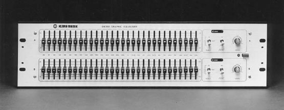
Figure 13.1 A typical two-channel graphic equaliser. (Courtesy of Klark-Teknik Research Ltd)
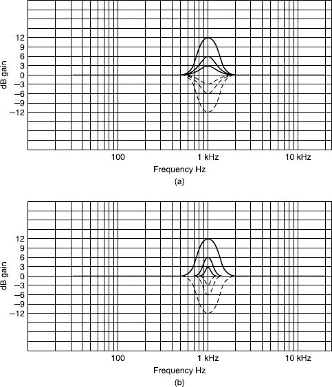
Figure 13.2 Two types of filter action shown with various degrees of boost and cut. (a) Typical graphic equaliser with Q dependent upon degree of boost/cut. (b) Constant Q filter action
Many graphic equalisers conform to this type of action, and it has the disadvantage that a relatively broad band of frequencies is affected when moderate degrees of boost or cut are applied. The second type maintains a tight control of frequency bandwidth throughout the cut and boost range, and such filters are termed constant Q, the Q remaining virtually the same throughout the fader’s travel. This is particularly important in the closely spaced one-third-octave graphic equaliser which has 30 separate bands, so that adjacent bands do not interact with each other too much. The ISO centre frequencies for 30 bands are 25 Hz, 31 Hz, 40 Hz, 50 Hz, 63 Hz, 80 Hz, 100 Hz, 125 Hz, 180 Hz, 200 Hz, 250 Hz, 315 Hz, 400 Hz, 500 Hz, 630 Hz, 800 Hz, 1 kHz, 1k25 Hz, 1k8 Hz, 2 kHz, 2k5 Hz, 3k15 Hz, 4 kHz, 5 kHz, 6k3 Hz, 8 kHz, 10 kHz, 12k5 Hz, 16 kHz, and 20 kHz. The value of using standard centre frequencies is that complementary equipment such as spectrum analysers which will often be used in conjunction with graphic equalisers have their scales centred on the same frequencies.
Even with tight constant Q filters, the conventional analogue graphic equaliser still suffers from adjacent filter interaction. If, say, 12 dB of boost is applied to one frequency and 12 dB of cut applied to the next, the result will be more like a 6 dB boost and cut, the response merging in between to produce an ill-defined Q value. Such extreme settings are, however, unlikely. The digital graphic equaliser applies cut and boost in the digital domain, and extreme settings of adjacent bands can be successfully accomplished without interaction if required.
Some graphic equalisers are single channel, some are stereo. All will have an overall level control, a bypass switch, and many also sport separate steep-cut LF filters. A useful facility is an overload indicator – usually an LED which flashes just before the signal is clipped – which indicates signal clipping anywhere along the circuit path within the unit. Large degrees of boost can sometimes provoke this. Some feature frequency cut only, these being useful as notch filters for getting rid of feedback frequencies in PA / microphone combinations. Some can be switched between cut / boost, or cut only. It is quite possible that the graphic equaliser will be asked to drive very long lines, if it is placed between mixer outputs and power amplifiers for example, and so it must be capable of doing this. The ‘+20 dBu into 600 ohms’ specification should be looked for as is the case with mixers. It will be more usual though to patch the graphic equaliser into mixer output inserts, so that the mixer’s output level meters display the effect on level the graphic equaliser is having. Signal-to-noise ratio should be at least 100 dB.
The graphic equaliser can be used purely as a creative tool, providing tone control to taste. It will frequently be used to provide overall frequency balance correction for PA rigs. It has formerly been used to equalise control room speakers, but poor results are frequently obtained due to the fact that a spectrum analyser’s microphone samples the complete room frequency response whereas the perceived frequency balance is a complex combination of direct and reflected sound arriving at different times. The graphic equaliser can also change the phase response of signals, and there has been a trend away from their use in the control room for monitor EQ, adjustments being made to the control room acoustics instead.
The parametric equaliser was fully described in ‘Equaliser section’, Chapter 5.
The compressor/limiter
The compressor/limiter (see Fact File 13.1) is used in applications such as dynamics control and as a guard against signal clipping. Such a device is pictured in Figure 13.3. The three main variable parameters are attack, release and threshold. The attack time, in microseconds (μs) and milliseconds (ms), is the time taken for a limiter to react to a signal. A very fast attack time of 10 μs can be used to avoid signal clipping, any high-level transients being rapidly brought under control. A fast release time will rapidly restore the gain so that only very short-duration peaks will be truncated. A ducking effect can be produced by using rapid attack plus a release of around 200–300 ms. A threshold level is chosen which causes the limiting to come in at a moderate signal level so that peaks are pushed down before the gain is quickly reinstated. Such a ducking effect is ugly on speech, but is useful for overhead cymbal mics for example.
A slow release time of several seconds, coupled with a moderate threshold, will compress the signal dynamics into a narrower window, allowing a higher mean signal level to be produced. Such a technique is often used in vocals to obtain consistent vocal level from a singer. AM radio is compressed in this way so as to squeeze wide dynamic range material into this narrow dynamic range medium. It is also used on FM radio to a lesser extent, although very bad examples of its application are frequently heard on pop stations. An oppressive, raspy sound is the result, and in the pauses in between items or speech one hears the system gain creeping back up, causing pumping noises. Background noise rapidly ducks back down when the presenter again speaks. The effect is like listening to a tape with noise reduction encoding, the reciprocal decoding being absent.
Fact file 13.1 Compression and limiting
A compressor is a device whose output level can be made to change at a different rate to input level. For example, a compressor with a ratio of 2:1 will give an output level that changes by only half as much as the input level above a certain threshold (see diagram). For example, if the input level were to change by 6 dB the output level would change by only 3 dB. Other compression ratios are available such as 3:1, 5:1, etc. At the higher ratios, the output level changes only a very small amount with changes in input level, which makes the device useful for reducing the dynamic range of a signal. The threshold of a compressor determines the signal level above which action occurs.
A limiter is a compressor with a very high compression ratio. A limiter is used to ensure that signal level does not rise above a given threshold. A ‘soft’ limiter has an action which comes in only gently above the threshold, rather than acting as a brick wall, whereas a ‘hard’ limiter has the effect almost of clipping anything which exceeds the threshold.
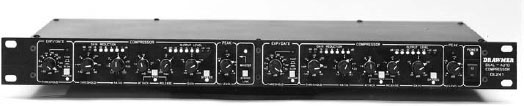
Figure 13.3 A typical compressor/limiter. (Courtesy of Drawmer Distribution Ltd)
Many units offer separate limiting and compressing sections, their attack, release and threshold controls in each section having values appropriate to the two applications. Some also include gates (see ‘Noise gates’, Chapter 7) with variable threshold and ratio, rather like an upside-down limiter, such that below a certain level the level drops faster than would be expected. ‘Gain make-up’ is often available to compensate for the overall level-reducing effect of compression. Meters may indicate the amount of level reduction occurring.
Echo and reverb devices
Echo chamber
Echo, or more properly reverb, used to be produced literally by setting aside a suitable reflective room in which was placed a loudspeaker and two microphones, the mics being placed a fair distance apart from each other, and from the speaker (see Figure 13.4). Signal was sent to the speaker at a fairly high level, which excited reflections in the room. The two microphones provided the ‘stereo’ echo return signals. The technique was undoubtedly successful, quality varying according to room size, shape and acoustic treatment. Pre-delay (see Fact File 13.2) could be used to simulate reflections from more distant surfaces.
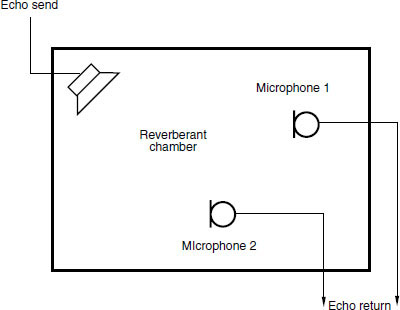
Figure 13.4 In a reverberation chamber the send is fed to a loudspeaker which in turn is used to excite the room. The returns are fed from two microphones placed in the reverberant field
Fact file 13.2 Simulating reflections
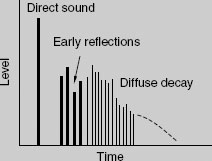
Pre-delay in a reverb device is a means of delaying the first reflection to simulate the effect of a large room with distant surfaces. Early reflections may then be programmed to simulate the first few reflections from the surfaces as the reverberant field builds up, followed by the general decay of reverberant energy in the room as random reflections lose their energy (see diagram).
Pre-delay and early reflections have an important effect on one’s perception of the size of a room, and it is these first few milliseconds which provide the brain with one of its main clues as to room size. Reverberation time (RT) alone is not a good guide to room size, since the RT is affected both by room volume and absorption (see Fact Files 1.5 and 1.6); thus the same RT could be obtained from a certain large room and a smaller, more reflective room. Early reflections, though, are dictated only by the distance of the surfaces.
Echo plate
The echo plate consists of a large, thin metal plate, several square metres in area. It is enclosed in an acoustically isolated housing. A driving transducer is attached close to one edge, and two or more receiving transducers are positioned at various other locations on the plate (see Figure 13.5). Signal is applied to the driving transducer which acoustically excites the plate. Its resonant properties ensure that vibrations persist for a usefully long period of time. The receiving transducers pick up the signal to provide the echo signal. The several receiving transducers can give various types of echo according to their positions, and more than one driving transducer can also be used to excite different resonant modes. A pre-delay signal (tape machine or solid-state delay) may be used to simulate a larger room. The plate is capable at its best of quite pleasing effects, and the twangy ‘plate-echo’ character of some settings is deliberately simulated in digital reverb devices in some of the programs because it suits some instruments well. The characteristics of plate reverb can be altered using a graphic equaliser if necessary. The plate must be well isolated acoustically because it is sensitive to both airborne and structure-borne vibrations. If it is mounted in a noisy area the echo return may contain echoey versions of the sound in the plate’s surroundings! A separate floor from the studio is often chosen.
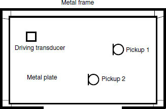
Figure 13.5 A reverberation plate is a metal sheet suspended from a frame, with transducers mounted at appropriate locations. Often the damping of the plate may be varied to alter the decay time of vibrations
Spring reverb
The spring reverb, popularised by the American Hammond organ company many years ago, consists basically of a coil of springy wire several millimetres in diameter and up to a metre or so long. It is acoustically excited by a transducer at one end, and other transducers, both at the far end and sometimes along the length, pick up the vibrations. Some are fairly sophisticated, utilising several springs and a number of transducers. The modest quality of their performance does not, however, prevent them from having an application in guitar amplifiers, and quite a pleasing reverb quality can be obtained. The springs are acoustically sensitive, and one frequently hears loud twangs and crashes through the speakers when guitar amplifiers are being moved about.
Digital reverb
The present-day digital reverb, such as that pictured in Figure 13.6, can be quite a sophisticated device. Research into path lengths, boundary and atmospheric absorption, and the physical volume and dimensions of real halls, have been taken into account when algorithms have been designed. Typical front panel controls will include selection of internal pre-programmed effects, labelled as ‘large hall’, ‘medium hall’, ‘cathedral’, ‘church’, etc., and parameters such as degree of pre-delay, decay time, frequency balance of delay, dry-to-wet ratio (how much direct untreated sound appears with the effect signal on the output), stereo width, and relative phase between the stereo outputs can often be additionally altered by the user. A small display gives information about the various parameters.
Memory stores generally contain a volatile and a non-volatile section. The nonvolatile section contains factory pre-set effects, and although the parameters can be varied to taste the alterations cannot be stored in that memory. Settings can be stored in the volatile section, and it is usual to adjust an internal pre-set to taste and then transfer and store this in the volatile section. For example, a unit may contain 100 pre-sets. The first 50 are non-volatile, and cannot be permanently altered. The last 50 can store settings arrived at by the user by transferring existing settings to this section. The method of doing this varies between models, but is usually a simple two- or three-button procedure, for example by pressing 5, 7 and ‘store’. This means that a setting in the non-volatile memory which has been adjusted to taste will be stored in memory 57. Additional adjustments can then be made later if required.
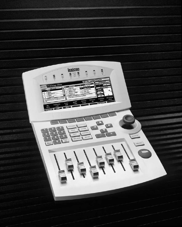
Figure 13.6 The Lexicon 960-L Multichannel effects system. (Courtesy of Stirling/Pure Distribution)
Several units provide a lock facility so that stored effects can be made safe against accidental overwriting. An internal battery backup protects the memory contents when the unit is switched off. Various unique settings can be stored in the memories, although it is surprising how a particular model will frequently stamp its own character on the sound however it is altered. This can be both good or bad of course, and operators may have a preference for a particular system. Certain processors sound a bit like clangy spring reverbs whatever the settings. Some sound dull due to limited bandwidth, the frequency response extending only up to around 12 kHz or so. This must be carefully looked for in the specification. Sometimes the bandwidth reduces with increasing reverberation or echo decay times. Such a shortcoming is sometimes hard to find in a unit’s manual.
In all the above reverb devices it should be noted that the input is normally mono and the output stereo. In this way ‘stereo space’ can be added to a mono signal, there being a degree of decorrelation between the outputs. Occasionally, a reverb device may have stereo inputs, so that the source can be assumed to be other than a point.
Multi-effects processors
Digital multi-effects processors such as that shown in Figure 13.7 can offer a great variety of features. Parametric equalisation is available, offering variations in Q, frequency and degree of cut and boost. Short memory capacity can store a sample, the unit being able to process this and reproduce it according to the incoming signal’s command. MIDI interfacing (see Chapter 14) has become popular for the selection of effects under remote control, as has the RS 232 computer interface, and a floppy-disk drive is sometimes encountered for loading information. Repeat echo, autopan, phase, modulation, flange, high and low filters, straight signal delay, pitch change, gating, and added harmony may all be available in the pre-sets, various multifunction nudge buttons being provided for overall control. Many units are only capable of offering one type of effect at a time. Several have software update options so that a basic unit can be purchased and updates later incorporated internally to provide, say, longer delay times, higher sample storage capacity, and new types of effect as funds allow and as the manufacturer develops them. This helps to keep obsolescence at bay in an area which is always rapidly changing.
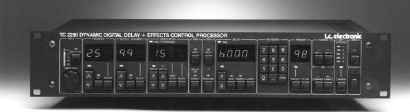
Figure 13.7 The tc 2290 multi-effects processor. (Courtesy of tc Electronics)
Frequency shifter
The frequency shifter shifts an incoming signal by a few hertz. It is used for acoustic feedback control in PA work, and operates as follows. Feedback is caused by sound from a speaker re-entering a microphone to be reamplified and reproduced again by the speaker, forming a positive feedback loop which builds up to a continuous loud howling noise at a particular frequency. The frequency shifter is placed in the signal path such that the frequencies reproduced by the speakers are displaced by several hertz compared with the sound entering the microphone, preventing additive effects when the sound is recycled, so the positive feedback loop is broken. The very small frequency shift has minimal effect on the perceived pitch of the primary sound.
Digital delay
The digital delay line is incorporated into any substantial sound reinforcement installation as a matter of course. Consider a typical SR setup which may consist of main speakers each side of the stage (or against the proscenium arch or ‘prosc’ in a theatre); front-fill speakers across the front of the stage; additional speakers covering extreme right- and left-hand sides under galleries; a line of speakers under a gallery covering the rear of the stalls; and a flown cluster covering an upper balcony, these latter speakers being rigged somewhat forward of the stage. Arrival times of the sounds from the various speakers to a particular location in the auditorium will of course vary due to the different physical path lengths, and the sound can be quite blurred as a result. Comb-filtering effects – abrupt attenuation of sound at certain frequencies as sound from one speaker is cancelled by anti-phase sound coming from another due to the different path lengths – can also be encountered at some locations, and a slow walk from one side of an auditorium to the other whilst listening to pink noise will quite often make these problems apparent.
Digital delay lines are patched in between the mixer’s outputs and the power amplifiers to alleviate the problem (digital mixers often incorporate delays on their outputs for this sort of application) and are set up as follows. Firstly, the sound of sharp clicks, rather like those of a large ticking clock – about one tick per second – is played through the main speakers each side of the stage with the other speakers switched off. Whilst standing close to the front of the stage, the front-fill speakers can then be added in. The clicks from these will reach the listener sooner than those from the main speakers, and the clicks will sound blurred, or perhaps even a double click will be heard each time. Adding a delay of perhaps 10 ms or so to the front-fills will bring the sound back into sharp focus, the exact value of delay needed depending upon the distance between the listener and the two sets of speakers. The front-fills are then switched off, and the listener moves to the side, under the balcony, and the speakers covering these areas are switched on. Again, indistinct clicks will be heard, and a delay to the side speakers of perhaps 25 ms will be required here to bring the sound into focus. For the line of speakers covering the rear stalls, a delay of perhaps 50 ms will be found to be needed. A rule of thumb when setting initial values is that sound travels just over a foot per millisecond, and so if, say, the line of rear stalls speakers is about 50 feet in front of the main stage speakers, an initial setting of 50–55 ms can be set. Many delay devices will also display the delay in terms of feet or metres, which is very useful. Moving up to the balcony, the flown cluster can now be switched on. A delay of perhaps 120 ms will be needed here to time-align the flown cluster with the main speakers each side of the stage. As well as giving a much cleaner sound, the use of delays in this manner also has the effect of making the speakers forward of the stage ‘disappear’, and the sound appears to come just from the stage itself.
As air temperature rises, sound travels faster, and delay settings obtained in a fairly cold auditorium during the day may well be a little high for the evening concert when the air is somewhat warmer. Some digital delay devices have an input for a temperature sensor, and if this is used the delay settings will automatically adjust to compensate for temperature changes.
Several computer-based systems are available which in conjunction with measuring microphones placed in the auditorium will display required delay settings for the various speaker locations when special test tones are played through the system. Additionally, using pink noise to drive the speakers the EQ curve requirements for flat frequency responses can be displayed, and parametric equalisation can be used to mirror the display curves. A word of caution concerning EQ settings – air absorbs high frequencies to a rather greater extent than low frequencies, and sounds coming from a distance naturally sound duller. At a distance of 50 metres, assuming a 20°C temperature and 20 per cent relative humidity, there is about a 10 dB loss at 8 kHz, and about a 35 dB loss at 16 kHz. Measuring microphones placed some distance from flown speakers will therefore register treble loss as a natural consequence of air absorption, and one must add treble boost with caution. An unnaturally bright sound can result, and excessive power can be fed to high-frequency horns.
Miscellaneous devices
The Aphex company of America introduced a unit called the Aural Exciter in the 1970s, and for a time the mechanisms by which it achieved its effect were shrouded in a certain amount of mystery. The unit made a signal ‘sparkle’, enhancing its overall presence and life, and it was usually applied to individual sounds in a mix such as solo instruments and voices, but sometimes also to the complete stereo signal. Such devices succeed entirely by their subjective effect, and several companies later produced similar units. They achieve their psycho-acoustic effect by techniques such as comb filtering, selective boosting of certain frequencies, and by introducing relatively narrow-band phase shifts between stereo channels.
Effects such as these go back a long way, and in many cases will be long obsolete and unavailable. But the value of such things as old valve (tube) compressors and limiters, distortion devices, tape and plate echoes, room simulators and other vintage-sounding devices such as certain guitar amplifiers is reflected in the market for ‘plug-ins’ for computer-based digital workstations: computer programs which have been developed to simulate the sounds of such old and well-loved devices. These things succeed purely on their own subjective terms, and are very much part of the creative process. Plug-ins do of course also provide up-to-the minute effects and processing. More is said on this subject in Chapter 10.
The de-esser cleans up closely miced vocals. Sibilant sounds can produce a rasping quality, and the de-esser dynamically filters the high-level, high-frequency component of the sound to produce a more natural vocal quality.
Connection of outboard devices
A distinction needs to be made between processors which need to interrupt a signal for treatment, and those which basically add something to an existing signal. Graphic and parametric equalisers, compressors, de-essers and gates need to be placed in the signal path. One would not normally wish to mix, say, an uncompressed signal with its compressed version, or an ungated with the gated sound. Such processors will generally be patched in via the mixer’s channel insertion send and returns (see Figure 13.8), or patched in ahead of the incoming signal or immediately after an output. Devices such as echo, reverb, chorus, flange are generally used to add something to an existing signal and usually a channel aux send will be used to drive them. Their outputs will be brought back to additional input channels and these signals mixed to taste with the existing dry signal (see Figure 13.9).
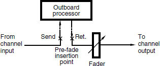
Figure 13.8 Outboard processors such as compressors are normally patched in at an insertion point of the required mixer channel
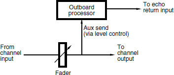
Figure 13.9 Reverberation and echo devices are usually fed from a post-fader auxiliary send, and brought back to a dedicated echo return or another channel input
Sometimes just the effects signal will be required, in which case either the aux send will be switched to pre-fade and that channel’s fader closed, or the channel will simply be de-routed from the outputs. The channel is then used merely to send the signal to the effects unit via the aux. The returns will often contain a degree of dry signal anyway, the ratio of dry to effect being adjusted on the processor.
Figure 13.10 shows a multi-effects processor.
MIDI control for selecting a programme has already been mentioned. Additionally, MIDI can be used in a musical way with some devices. For instance, a ‘harmoniser’ device, designed to add harmony to a vocal or instrumental line, is normally set to add appropriate diatonic harmonies to the incoming line in the appropriate key with the desired number of voices above and/or below it. Results are thereafter in the hands of the machine. Alternatively, a MIDI keyboard can be used to control the device so that the harmoniser adds the notes which are being held down on the keyboard. Composition of the harmonies and voice lines is then under the control of the musician. This can be used in recording for adding harmonies to an existing line, or in a live situation where a keyboard player plays along with a soloist to generate the required harmonies.
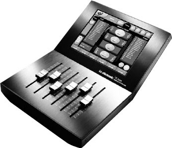
Figure 13.10 The tc Electronics System 6000 multi-effects processor. (Courtesy of tc Electronics)
Recommended further reading
White, P. (2003) Basic Effects and Processors. New Amsterdam Books