
Chapter 3
Systems Requirement Analysis
In the previous chapters, we have learned about the basic systems concepts, system life cycle, and major processes that are involved in systems engineering design. No matter what kind of system is being designed, from a small appliance to a complex system like a Boeing 787, they all share the same characteristics; that is, every design is driven by systems requirements. Requirements driven is perhaps the most significant characteristic for systems engineering. In the early years of man-made system history, the importance of the system requirements was often ignored; designers used to start their configuration process with little knowledge of what users really wanted, or started with partial understanding of the system needs, hoping to incorporate more needs during the design process. With many failures, costs, and delays involved in the later changes of system needs, lessons were learned the hard way. We now have realized that without having a complete picture of what users need and formally translating that into systems requirements, it is nearly impossible to design a complex system within its time and budget limits. The requirements are vital to the success of the system design. Although systems requirements were briefly introduced in Chapter 2, we feel that it is necessary to revisit the concept of system requirements here in greater detail for readers to grasp the idea of performing requirements analysis (RA). This chapter is perhaps one of the most important chapters in the whole book, as it lays out the foundations of systems design, so that the system is built effectively and efficiently. System requirements analysis (SA) is perhaps the determining point for systems success; as the old proverbs tell us, “the pen follows where the mind reaches,” or “when conceiving ideas first, writing is easier.” In Chinese culture, it was said that “grinding the ax first will facilitate cutting the firewood.” These proverbs all imply the same meaning; that is, spending effort in early planning should not be neglected, just like RA in system planning.
In this chapter, we will
- Define system requirements in greater detail; describe the nature and type of requirements and their characteristics.
- Introduce the format of system requirements. What is the common structure for system requirements and major syntax components that should be included in a system requirement statement?
- Define the characteristics of a good requirement. What should be included and what should be avoided in writing a system requirement?
- Describe the sources for obtaining the original requirements; the fundamental techniques used in requirements capture and collection process. Basic techniques include user interview, questionnaire and survey, observation, study of similar systems, documentation and historical reports, critical incident/accident analysis, and standards. A comparative analysis is provided for these techniques so that we know when to use which method in the requirements collection process.
- Introduce the basic concepts of RA; describe the major analysis and trade-off models that are used in RA, including affinity diagram, quality function deployment (QFD) model, and house of quality (HOQ).
- Introduce the concepts of requirements management; illustrate the process of systems requirement capture, organization, and documentation. Learn how to use the software tool CORE to manage systems requirements.
On completion of this chapter, we expect readers to have become familiarized with the concepts and models that are related to systems requirements, know how to write a good requirement, know how to organize requirements, and perform necessary analysis of the different types of requirements using appropriate models.
3.1 What Is a System Requirement?
In Chapter 2, we defined the system requirements briefly: A system requirement is a necessary attribute or function that a system must have or provide. It is a formal statement to identify a capability, characteristic, or quality that a system must have to provide value and utilities to system users.
From Chapter 2, we learned that system requirements are important for systems design. The requirements are the driving forces for the design activities; requirements define the need to develop the systems, describe the system functionality, and also regulate system engineering efforts for the development of the system. For many years, the role of the systems requirements was not given enough attention; many designers, especially the engineers who were doing the “real” design work, such as hardware developers and software programmers, believed that the actual design work was the real systems engineering process, while the requirements-related work was primarily documentation, and could be accomplished within the design work. Not enough attention was given to the requirements-related efforts, including spending the time to capture the complete set of requirements, understanding and organizing the requirements, and resolving and trading off conflicting requirements. For simple systems with small numbers of requirements involved, the role of RA might not be as critical as in complex system design. But, for a complex system design that involves hundreds or thousands of requirements, we cannot expect these requirements to come to us naturally as we carry out the design work. There are often misconceptions about “stated” requirements and “real” requirements. Stated requirements are provided by systems customers; for example, via commonly used requests for proposals (RFP) and statements of work (SOW). These requirements are usually stated in the customer’s language and at a very high and abstract level. The real systems requirements, which are stated in precise designer language, define the systems functionality and utility. These are the requirements that drive the system design activities. There are often huge differences between user-statement requirements and real system requirements; the real system requirements are based on the original user requirements, but user-statement requirements cannot design the system themselves; usually, they are incomplete, vaguely stated, in users’ naïve language, and, sometimes, controversial in nature. These users’ requirements need to be organized, filtered, translated, expanded, and formatted into a complete, technically sound, and accurate set of system requirements to be implemented. This translation process, often referred to as the requirements analysis (RA), usually occurring in the early design stages, is most critical for understanding the needs of the customer and forming a foundation for proper communication between designers and customers.
It is well understood that a little planning goes a long way and systems requirements analysis is the foundation of system planning. The quality of systems requirements and their analysis are of utmost importance for overall system success; their impact reaches all the way to the end of the system life cycle.
Now we know what a requirement is and why RA is important, and from the previous chapter, we have learned that a system requirement should have the following syntax/format:
System (or subsystem) XYZ + SHALL + verb (action) + desired outcome/performance level + operational/environmental conditions
This is the general format/syntax for a properly written requirement. Although the format might vary for different type of requirements, there is one important characteristic that all system requirements should have; that is, it is a SHALL statement. A SHALL statement is different from should, would, and may statements; it means that it is mandatory and contractually binding for this need; as a requirement, the designed system must comply with it. The other words, such as may or would statements, usually convey options to the designers; the strength of these statements is not as strong as the SHALL statement.
3.1.1 Types of Requirements
Systems requirements can be categorized into one of the following four major categories:
- Functional requirements: A system functional requirement usually defines a desired function that the system should provide or a function that the system must carry out. Sometimes, a functional requirement is also referred as a WHAT requirement; for example, the automated teller machine (ATM) shall enable customers to deposit cash or checks and withdraw up to x dollars at a time from their checking accounts on a 24 h a day and 7 days a week basis.
- Performance requirements: Unlike functional requirements, performance requirements specifies HOW WELL the system or systems function shall be performed; for example, the automobile system shall start the engine within 6 s after the driver turns the ignition key under normal weather conditions; the system shall have an operational availability (Ao) of 99.99%.
- Constraint requirements: A constraint requirement provides limitations on the design or construction of the system. Constraint requirements are usually part of the results of system feasibility analysis and strategic planning, regulating the design space and pointing in a certain direction for the design. For example, “The automobile system shall use both grid electricity and B20 biodiesel as the energy source.”
- Verification requirements: Verification requirements are those that define what and how is intended to verify or test the functional requirements or performance requirements for acceptance of the system/components. Verification requirements specify the verification events, methods, and procedures to prove the satisfaction of the system requirements. Usually, systems functional requirements and performance requirements contain the verification criteria within the requirements themselves. If there is a special need for the verification, or a unique verification method/technology to be applied, the verification requirements need to be defined. Slightly different from the functional requirements and performance requirements, a verification requirement contains four basic elements: a verification objective, a verification method (inspection, analysis, test, or demonstration), the verification environment, and success criteria. For example, system operational availability shall be calculated using the definition given by MIL-STD-721, conducted by a government-certified contractor; the demonstration shall show that the system, under the defined operational environmental conditions, shall have an operational availability of at least 99%.
There are also some other types of categorization; for example, depending on the sources, requirements can be classified as originating requirements (those that come directly from customers), derived requirements (requirements obtained from RA to further refine the originating requirements), and design decision requirements (not explicitly from customers, but from the design team analysis results, necessary for fulfilling customer requirements). Based on the group of people involved, requirements may be classified as end-user requirements, management/business requirements, or maintenance/support requirements.
All these different types of requirements overlap with each other; they describe the system needs from a different perspective, just as the different system models describe the system from different angles. In this text, we will be touching on different types of requirements in different sections for their intended purposes—such as functional requirements for functional analysis and user requirements when talking about human factors—in later chapters.
3.2 Characteristics of Systems Requirements
Requirements are the key to project success, as the quality of the requirements determines the quality of the understanding of the systems need. Writing requirements may look straightforward, but they are a real challenge. Writing good requirements requires engineering knowledge of the system, skills in dealing with humans, and, most of all, the ability to think critically and creatively. As a systems engineer, one should know what a good requirement should look like. Although different types of systems vary a great deal in complexity and in nature, the good news is that no matter what type of system you are working on, the criteria for good requirements are essentially the same. Understanding these criteria not only helps us write good requirements, but also validates any other requirements that other people develop. Generally speaking, a good requirement should have the following characteristics:
- A good requirement is correct. A requirement being correct means that it is technically feasible, legal, achievable (within the organization’s capability), and complies with the organization’s long-term strategic planning goals.
- A good requirement is complete in and of itself. In other words, a good requirement statement should contain the complete information that pertains to the requirement itself.
- A good requirement is clear and precise. The requirement should not contain any ambiguous meanings that cause confusion for the people who read them. Imprecision arises from a number of reasons in a requirement, including
- The use of undefined terms or unfamiliar acronyms
- The use of imprecise quantifiers and qualifiers
- The use of indefinite sources and incorrect grammar
- A good requirement is consistent with other requirements. A requirement statement should use the unified language standard, syntax, and glossary across all the requirements for the system, to avoid conflict between requirements. By conflict we mean the writing style and format, not mainly the content. Sometimes, requirements in different categories have contradicting goals; for example, customers want to cut their costs but also desire more functionality and reliability in the system. These types of contradiction can usually be resolved by conducting a trade study to achieve a break-even point or a balance between the requirements.
- A good requirement is verifiable. For any requirement we develop, we should always ask this question: Is there any way we can determine that the system meets this requirement or not? If we cannot provide a good answer to this question, then the requirement is considered not to be verifiable. Generally speaking, a requirement can be verified in one of three ways: (1) by inspection for the presence of a feature or function, such as verifying the existence of a functional requirement; (2) by testing for correct functional behavior; for example, verifying the performance requirements for a certain function; and (3) by testing for correct nonfunctional attributes, such as verifying the usability of the system interface. For the requirements to be verifiable, the conditions and states for functional requirements must be clearly specified. For nonfunctional behavior, precise ranges of acceptable quantities must be specified.
- A good requirement is traceable. Any requirement should be upward and downward traceable; we should know where it comes from and where it goes from here. As we mentioned in the system engineering design concepts, systems design is requirement driven, and every requirement has a source, either originating from customers or derived by the design activities based on the customer needs. For this reason, every requirement has a rationale associated with it; that is, we know why there is such a requirement. We can also say that a good requirement is necessary; there are no redundant requirements, and every requirement can be traced back to its source and is addressed by at least one function, feature, or attribute. If this requirement is not being addressed by any functions, the validity and necessity of this requirement need to be questioned.
With the above characteristics, we can easily know the requirement’s source, understand what users are involved, and develop a clear idea of what we must do to fulfill this requirement and how to verify it afterward. When writing requirements, we should really spend time and effort to make sure all requirements follow these good criteria. The following list provides a general set of guidelines for developing good requirements (Telelogic 2003):
- Avoid using conjunctions (and/but/or) to make multiple requirements. Make sure one requirement focuses on one subject at a time. A requirement containing multiple elements might cause confusion and difficulties for verification.
- Avoid let-out phases, such as “except,” “unless,” “otherwise,” and so on.
- Use simple sentences. For every requirement that addresses one single aspect of the system, a simple sentence is usually sufficient to express the requirement. Using a simple sentence makes it easier to be understood, thus minimizing any ambiguity.
- Use limited vocabulary. Ideally, the vocabulary size should be fewer than 500 words. A limited vocabulary is easier for communication and translation into technical language. This is more critical for systems that involve international audiences.
- Include information about the type of users in the requirements, if possible.
- A focus on the results is to be provided for the users in the requirement statement.
- The desired results/outcomes should be stated in verifiable criteria.
- Avoid using fuzzy, vague, and general words to minimize confusion and misunderstanding. Examples of such words are “flexible,” “fault tolerant,” “high fidelity,” “adaptable,” “rapid” or “fast,” “adequate,” “user friendly,” “support,” “maximize,” and “minimize.” (“The system design shall be flexible and user friendly” is an example.) Fuzzy words also cause difficulty for verification; for example, if a web page is to be user friendly, what is meant by user friendly? Rather than inserting “user friendly” into the requirement, it is better to rewrite the requirement in a more verifiable way, such as, “the web page shall be completely loaded in less than 7 s for a T1 internet connection speed” and “the web page shall enable the user to find the information by exploring no more than 5 levels of categories.”
Here are some examples of some good written requirements:
A single pilot shall be able to control the aircraft’s angle of climb with one hand.
The pilot shall be able to view the airspeed in daytime and nighttime conditions.
Requirements are the foundations of system design; developing a complete set of good requirements provides a good starting point for project success. Making a good start can save us a lot of time and effort. Writing requirements is a process of translation from the gathered user needs into a well-structured technical document. During this translation process, it is inevitable that individual experiences will impact the understanding and quality of the requirement statements; as a matter of fact, in the field of requirement engineering, there is no absolute right or wrong for any requirements. By using the characteristics of good requirements and following the guidelines to write them, we can ensure the requirements developed may be easily understood and thus facilitate the design process, translating the requirements to system functions and eventually the final system. In the next section, we will discuss sources of requirements and how requirements are captured and organized before they are analyzed.
3.3 Requirements Capture Technique
Some key points need to be kept in mind for an effective process of requirement capture and collection. These key points are essentially nontrivial for large, complex system design, as there are hundreds and even thousands of requirements involved in the design. These key points include
- Identify the stakeholders for the system.
- Identify the requirement sources with users’ involvement.
- Apply a variety of data collection techniques.
- Use a computer-based software tool to document and manage the requirements.
Good requirements come from good sources. To determine the requirement sources, we first need to identify the stakeholders of the system. As discussed in Chapter 2, there are two major types of system stakeholders: First, there are system users, as mentioned in Chapter 2—mainly systems users/operators and maintainers—these are the direct user groups; besides those who directly interact with the system, there are also people who indirectly influence the system users, such as administrators, supporting personnel, and those who design the systems. Every user group plays a role in overall system requirement development, more or less; they each address a different aspect of the system. For example, end users might primarily concentrate on system functionality and usability; the system designers, on the other hand, might consider the long-term sustainability and environmental friendliness of the system, while the management primarily focus on the profitability and life cycle cost (LCC) of the project. These are all important factors for design project success. To develop a complete picture of the system requirements, we need to reach out to all these stakeholders.
There are many sources from which to gather the requirements. The original requirements come directly from the customers. Government customers, such as the Federal Aviation Administration (FAA) and Department of Defense (DoD), have a formal procedure to initiate system needs for systems developers to start the requirements collection process. An RFP is commonly used for government system acquisition and development.
An RFP is a formal document that an organization issues to invite the potential vendors/developers/contractors to bid for the project.
A typical RFP should include the following information:
- Introduction.
- Organization background: Describe the background of the organization or company who is issuing the RFP.
- Statement of purpose: Define the mission for the project; solicit proposals to meet these mission requirements and describe detailed proposal requirements; outline the general process for evaluating proposals and selecting criteria.
- Scope of the system and terms/conditions: Define the scope of the system to be developed; specify any terms and conditions that are related to the life cycle and payment for the system.
- Other related issues: Communication, coverage and participation, ownership agreement, disclosure and extension, any legal disclaimers, and so on.
- Communication information: Point of contact (POC) information, phone/fax number, email address, and so on.
- Technical requirements.
- This section defines the background of the system to be acquired and the technical objectives that are to be achieved by the system. Information on project deliverables are specified and technical measures are provided to measure system success. If the system is part of a larger system, the preferred technical approach and desired interface with other systems are also specified; these will identify the limitations to the technological approach.
- The format of the proposal to bid on the RFP should be explained in detail, including major sections, page limits, and page format if desired (such as font type, font size, line space, page margins, etc.). Many organizations publish their own standard for proposals, such as the DoD and the National Aeronautics and Space Administration (NASA), which have their own proposal guidelines, with which every proposal to is required to comply. Usually, a link to these guidelines is provided in the RFP for the proposers to follow.
- Business requirements: This section specifies the major milestones of the deliverables, the expected budget of the project, and the deadlines for the submission of the proposal.
- Evaluation criteria: Describe the major criteria that will be used to evaluate the proposal and the number of awards expected for this project. Typical evaluation criteria include technical capability of the proposer’s organization, technical soundness of the proposed solution/design, economic feasibility of the proposed budget, overall project management and control, and personnel qualification. Sometimes a points system is used to compare the competing proposals.
When an organization is trying to bid for the project, the RFP is a good source for the overall requirements, but, generally speaking, the requirements in the RFP are usually not sufficient to completely understand the requirements of the proposed system; additional information and sources are usually necessary to collect more requirements that have been omitted from the RFP, such as the relevant standards and codes for similar systems, research findings, published design guidelines, and, of course, surveys of the customers for whom the systems are being designed.
A successful bid leads to the award of the project, and as a common requirement before any work starts and funding is released, a SOW is developed by the organization awarded the contract to submit to the customer. The SOW, once approved by the customer, is a contractually binding document that specifies the relationships and responsibilities of both the contractors and the customers, defining the major milestones and deliverables for the life cycle of system development. A SOW should be developed based on the requirements and structures in the corresponding RFP; usually it includes the following sections:
- Background of the project
- Scope of the project
- Background of the organization
- Period of performance
- Technical approach
- Major milestones and deliverables
- Evaluation standard and criteria
- Design team, business personnel, and their qualifications
- Payment method and schedules
Requirements extracted from RFPs are usually very high level; they cover the minimum requirements for the system to be acquired or designed. As mentioned above, to obtain the complete set of requirements, we cannot solely rely on the RFP; research is needed to extend the scope of the requirements covered in the RPF to a wider range of sources. These sources, including standards/codes/regulations, published guidelines and data, and even customer surveys, are necessary for us to obtain hidden and implicit requirements, and to acquire a comprehensive understanding of what is really needed for the desired systems. These sources are particularly important for projects that are not RPF initiated. In the following section, we will discuss these various sources that could be used to collect potential requirements, as well as some of the techniques that are commonly used in capturing requirements.
- User interviews: This is one of the most popularly used techniques and sources for collecting requirements concerning product design and quality improvement. Interviews involve asking users a number of questions; each question addresses a certain aspect of the system to be designed. The interview can be conducted face-to-face or in a remote fashion, such as using the telephone or instant messenger (IM). The interview can be broadly classified as structured, unstructured, or semistructured, depending on how well the questions were predefined and organized. The structured interview looks for answers for specific questions of interest, but lacks flexibility to explore other issues that are beyond the scope of the predefined questions. On the other hand, the unstructured interview enables users to express their opinions freely without being limited to a set of predetermined questions. This can often lead to some issues that have not been thought of by the designers, but the problem with unstructured interviews is that they are time consuming and often inefficient in helping users to think, as some users are better at giving opinion only when specific questions are asked. To help users to provide answers and inputs, sometimes a scenario can be used to aid in the interview session. As interviews are typically conducted one-on-one, focus groups and workshops may be used as an alternative to interviews to achieve group dynamics and interaction effects on the users. The use of groups can gain many benefits that individual interviews do not have; for example, through discussion and brainstorming, the focus group can help different users to gain a consensus view that certain items are required, solving any disagreement or conflict between different opinions. When controlled and structured well, focus groups and workshops can be very effective in collecting a set of validated user requirements.
- Survey and questionnaire: These are very popularly used in a wide range of applications and fields, such as social studies, behavioral science, and market analysis. Surveys and questionnaires use a series of questions to seek inputs from a large pool of users. A questionnaire may use closed or open questions. Closed questions have limited answers for users to choose, such as multiple-choice questions or a selection from a Likert scale, while open questions do not limit users’ answers; users can enter their own words in the answers, like an essay question in an examination. Unlike interviews, surveys and questionnaires can be done off-line; they can be distributed to the users and completed without being monitored or administered. Compared to interviews, surveys and questionnaires can reach a wider range of people within a short period of time, without committing too many resources; usually mail or email is sufficient. However, since they are conducted in an asynchronized way without the questioner being present, there is no guarantee that the user will respond to the survey. The response rate is the most critical issue for requirement collection via surveys and questionnaires. A typical response rate for a survey and questionnaire study is around the 20%–40% range. The design of the questionnaire is the most critical factor impacting the response rate; many techniques have been developed to improve the clarity, flexibility, and friendliness of the questionnaire design. Another concern for the questionnaire design is its validity; in other words, we have to make sure the users actually take time to read the questions, and think about them, before writing down their answers. Some techniques, such as asking the same questions in different places, have been used to validate users’ answers. Nevertheless, the questionnaire has been one of the most popular methods used in gathering users’ opinions, despite the disadvantages of low response rates. Questionnaires are often used in combination with other techniques; for example, during an interview session, a short questionnaire is often used at the end of the interview to obtain users’ feedback about anything that might have been omitted from the interview session.
- Observation: This involves spending time with users, observing how they do certain functions and how they perform tasks. When asked about their expectations of and preferences regarding systems, users are sometimes not good at telling the complete story about the whole system; the mental model of users is only related to what they do on a daily basis, and based on their experiences, the input given by users will only cover a subset of the whole spectrum of the system requirements. Observation can fill in the gaps in the details of user input, and provide a better understanding of the user’s needs more objectively and completely. Sometimes called naturalistic observation, the key to the success of observation is in the users’ natural working environment, trying not to disturb them when making the observations. To obtain greater insight into how the users feel, the observers can also take part in users’ tasks, participating in users’ functions, to get a first-hand experience of system functions. This is called an internal or inside observation. This is in contrast to a typical outside observation, where the observers adopt a passive role just to observe, and no active participation is involved. Since the observer is certainly limited in his/her cognitive resources, multiple observers are sometimes used to avoid missing features and subjectivity of personal understanding of the tasks. Technologies such as data logging and video/audio recording are used to aid data collection during observation, if permitted by users.
- Study of documents and reports: Historical documents and reports are good sources for eliciting requirements. Information on how systems were used and misused through historical sources can provide great insights for items that need to be included or improved in the next version of the system. These documents include, but are not limited to, system manuals, government and industrial standards and regulations, research articles and published guidelines, marketing and sales reports, and critical incident and accident reports. Standards, codes, and regulations should be one of the primary sources to be consulted for requirements, as many of the requirement sources, including the RFP and user inputs, do not necessarily include a complete reference to the standards. It is the designers’ responsibility to consult these published standards to comply with them, to make the design more efficient, and most importantly, to avoid any product liability lawsuit in the future. For example, in designing cars, the Federal Motor Vehicle Safety Standards and Regulations by the Department of Transportation should be consulted to include any important features in the design of the vehicle. There are many standards, and weeding through them can be time consuming, but the impact of ignoring any important standard can be significant. In systems engineering, the typically used standards include Occupational Safety and Health Administration (OSHA) standards, military standards and handbooks (MIL-STD/MIL-HDBK, DoD standards), NASA standards (NASA-STD), American National Standard Institute (ANSI) standards, Institute of Electrical and Electronics Engineers (IEEE) standards, and International Organization for Standardization (ISO) standards. Research findings in the published literature can also serve as an important source for eliciting requirements; these research studies will provide guidelines for researchers to look at potential variables that are involved in the design and help to design better methods to capture system requirements. Another source for potential requirements are historical reports on critical incident and accident events. Most companies and organizations have an established way of reporting any incidents, accidents, and defects when using the system. These events inform us of potential ways that users could make mistakes or errors when interacting with the systems. These mistakes, errors, and accidents, which occurred in the past, reveal the situations in which the system causes difficulties. Investigating these situations will reveal to designers what the causes and sources for these difficulties are and, as an important set of the system requirements, investigations of these incidents and accidents, and related factors such as environments and user interactions, will lead to a more reliable system and a better system maintenance design.
- Study of similar systems: At the current time, it is very difficult to think of any system that does not have any sorts of predecessors. On the other hand, there are always competitors with similar systems as well. Looking at predecessor systems or the current similar systems of others will certainly help designers to gain understanding of what should be included in their own design. To study similar systems, a combination of techniques can be used to collect data, including observation, interviews with users who have experience with different systems, questionnaires, user task analysis, and critical incident/accident studies, to look at data and information related to systems functions, operability, maintainability, user types/skills, and usability issues. Besides the main functional factors, some other useful analysis products should also be derived from the analysis of similar systems, including environmental factors for different systems and human factor issues that could be significant in making the systems successful.
A good review of some of the methods can be found in chapter 7 of Rogers et al. (2011). Readers can refer to their book for a side-by-side comparison of the different data collection methods and their advantages and disadvantages. The list above is by no means an exhaustive set of sources for obtaining systems requirements; they are just the most commonly used in systems engineering design. We have to keep in mind that, as every system is different, so are the requirements sources. A good system designer will not only think critically, but creatively as well. Some requirements will not be salient, and it takes great effort, resources, skills, and time to develop a good set of original requirements. This is the most important phase in the system design, as we have expressed many times in previous chapters; a good planning phase is the key to find the system stakeholders and the most appropriate requirement capture methods. With the complete set of requirements captured, the next step to conduct an in-depth RA to implement the requirements in the design.
3.4 Requirements Analysis (RA)
Requirements, especially those originating from users, come in different formats and are of different qualities; some are in users’ natural language, others are in a variety of media, video/audio, graphs/drawings, notes, and many more. For the design to implement these requirements, we need to elicit and record them in a strictly defined structure and syntax, as defined in the system requirements definition section. Moreover, many requirements are ad hoc, and do not follow a well-defined arrangement automatically; it is the designers’ responsibility to document, manage, and control these requirements according to engineering design standards, so that they may be further translated into systems functions. This is not to mention that no matter how complete the original requirements are, they still will be far from defining every factor of the system. Many of the unspoken requirements will have been taken for granted by the users; sometimes they are thought as common sense or just so straightforward that they are ignored in the collection of users’ views. Designers need to derive those hidden requirements or sometimes even make decisions or recommendations for those factors of which users have little experience. RA is an important design activity, following the original requirements elicitation, to analyze the captured user requirements, for the requirements to be implemented in the design. Generally speaking, RA usually involves the following major activities:
- Rewrite the user original requirements into the correct syntax format, the “shall” statement; make sure all requirements are written in a way that is clear, complete, verifiable, and unambiguous.
- Organize the requirements into different categories and hierarchies; map the requirements to systems architecture; derive the requirements that are not included in the original requirements using appropriate design models.
- Perform trade-off studies to prioritize the requirements, ranking them so that the most critical requirements are given more attention in the design.
- Document and record requirements using requirements management tools, establish semantics for relationships, and provide rationality and traceability for each requirement.
The purpose of RA is to prepare the requirements for the next step of the system design, which is functional analysis. The results of RA will facilitate the translation from system requirements to system functional structure; they serve as the bridge between users’ language and designers’ technical language. The most commonly used methods used in RA include affinity diagrams, scenarios, use cases, and QFD.
3.4.1 Affinity Diagram
An affinity diagram is a tool to organize a large set of captured requirements into a hierarchical structure based on their relationships. For thousands of years, people have been grouping different things into a limited set of categories, but it was not until the 1960s that the term was first used and a process was developed by the Japanese anthropologist Jiro Kawakita. The affinity diagram is also called the KJ diagram for that reason.
The affinity diagram is a good way to consolidate different ideas into a well-organized structure. It is well suited for RA with large amounts of collected data; especially after the interviews, focus groups, and brainstorming sessions, there are usually many difficulties processing the data collected. Besides the large volumes of data, the data might contain situations that are unknown or unexplored by the design teams; it might present circumstances that are confusing or disorganized. This happens more often when meeting participants with diverse experiences or incomplete knowledge of the area of analysis.
With the affinity-diagram-based analysis method, the design team can address the issues mentioned above by:
- Sifting through large amounts of data in a relatively short period of time.
- Encouraging shared decision-making, communication, and criticism to facilitate new patterns of thinking. With group efforts, design teams can break through traditional ways of thinking, enabling the team to develop a creative list of new requirements ideas in a very effective way.
The procedure of conducting an affinity diagram analysis is quite straightforward; with all the data collected, all you need are cards or sticky notes, a pen, and a large surface (a board, wall, or table) on which to place the cards.
- Step 1: Generate and display ideas. Record each requirement with a marker pen on a separate card. Randomly spread all the cards on the work surface so all cards are visible to everyone. The entire design team gathers around the cards and moves on to Step 2.
- Step 2: Sort and group ideas. It is very important that every individual member works on his/her own in this step; no collaboration/conversation/discussion is allowed. Every member takes time to look for the requirements that are related to each other in some way. Put all related cards in the same group and repeat until all cards have been considered. Note that a single-card group is allowed if this particular card does not fit into any other groups; if cards belong to multiple groups, make duplicates for those cards so that a copy can be placed in every group. Any member of the team may move a card to a different group if he/she disagrees with where it is currently placed. After all the members have done the grouping, move on to Step 3.
- Step 3: Agree on and create groups. It is now time for the team members to discuss their grouping results and the structure of the grouping diagram. By solving any potential conflicts and disagreements between the different members, changes can be made to the final grouping results. Repeat the process until a consensus has been achieved. When all the requirements are grouped, select a heading for each group and place it at the top of the group.
- Step 4: Subgrouping. Repeat Steps 1–3 on a large group to develop subgroups, or combine groups into “supergroups” if desired.
- Step 5: Document and record the final group structure.
Figure 3.1 illustrates a sample affinity diagram.

3.4.2 Scenarios and Use Cases
One of the objectives of RA is to understand what users really need and derive a complete picture from the lists of requirements, describing how the system will be used when it is built from the users’ perspective. It is desirable to tell a complete story, especially for the verification of the system requirements with users, so that they may gain an impression how the system will fulfill their needs, without needing to understand the technical background. There are different ways to describe the systems; among those, scenarios and use cases are the most commonly used tools. Especially for software-related systems, use cases are almost a standard design method (as in Unified Modeling Language (UML) for software engineering). Scenarios and use cases are not mutually exclusive; they are often used in combinations to capture different perspectives of the system’s behavior, and are also applied in different stages throughout the system life cycle.
A scenario is an informal description about how the system will be used by users. By understanding and compiling the requirements collected, system designers develop scenarios to tell a story about user task activities and systems functions, to explore and discuss any potential issues with the intended use of the system described. A scenario is usually written in plain narrative language, providing a natural way for system users and stakeholders to understand how the system will fulfill their needs. The focus of the scenario is user tasks and system responses, together with information necessary to describe the tasks, including environmental conditions, context, and any technological support information.
The scenario provides a natural way for explaining to the stakeholders what will be designed and how the systems will be used, facilitating communication between the users and designers, providing a good starting point for users to understand, and exploring the intended functions, context, and constraints, identifying any missed requirements and misunderstandings between the users and designers.
The procedure to develop a scenario is quite straightforward; it requires the designers to understand the requirements and the existing behaviors involved for such a system. Based on their understanding, designers describe a story of the system usage from the users’ standpoint, either in a first-person or a third-person perspective. For example, the following scenario is developed to illustrate the start-up of a hybrid vehicle:
Roger gets into his vehicle, he first puts in his car key and starts the vehicle, and the seat configures itself to Roger’s preset position. Roger then enters his trip information from home to his workplace into the dashboard menu; the onboard computer accepts this input, and provides information about the GPS route, traffic and weather information, and the estimated time of arrival. Roger presses “accept” regarding this recommended route and starts backing his car out of the garage, and then starts driving.
Note that, in the above example, all the verbs have been italicized; as we mentioned earlier, the scenario provides a starting point for requirements to be analyzed, and, eventually, system requirements need to be translated into functions and functional structure. There is a big gap between the requirements and functions, as they are stated in different formats; requirements are general, stated in natural language, while functions are more technical and very system dependent. But when a scenario is portrayed, all the potential system requirements are embedded within it; one can start by looking at all the verbs to derive system functions, as every system function involves some kind of action, which usually starts with a verb.
Another method used commonly in SA is use case analysis. Unlike the scenario, which focuses more on user tasks, use cases concentrate on the interaction between users and systems. Use cases were originally developed in the software engineering industry, in the object-oriented-design community. In UML-based software design, the use case diagram is used to model the dynamic part of the system, to describe the system behavior by defining the relationships between the users (actor) and system/subsystem elements.
As indicated by its name, a use case in system engineering is a sequence or list of action steps, allowing users and systems to interact. A use case is associated with actors; actors are the users of the system, through proper interaction, and they achieve their goals through use case actions. One use case is usually defined for one system function, this function could be a normal use of the system, or a maintenance function for handling system failure.
A use case analysis includes three elements: identification of the actors, a list of the system actions, and the interaction relationship between the actors and system actions; a use case diagram is developed to illustrate these three elements.
There is no standard procedure to develop a use case; it varies with different systems. A commonly used method includes the following steps:
- Identify the actors and their goals.
- Define the scenarios to achieve the goals. The scenario is described as a numbered list of steps that involves both actors and system (subsystem or system components) to achieve the goals. Each step is written as a simple straightforward statement of the interaction between the actors and the system.
- Make notes of extension of the use case: extension is the condition that results in different courses of actions or alternatives from the normal course of actions.
For example, a possible use case for a check account balance for an ATM system looks like this:
- The use inserts his/her bank card.
- The system prompts for the user’s account personal identification number (PIN).
- The user enters the PIN.
- The system verifies the PIN.
- The system displays a menu of choices.
- The user chooses the “check balance” option.
- The system displays the account type menu of choices (checking or saving).
- The user chooses an account type from the menu.
- The system retrieves the account information.
- The system displays the account information.
- The user quits from the account information.
- The system returns to Step 5.
An extension for this use case:
- 4.1 If PIN is not valid
- 4.1.1 The system displays error message
- 4.1.2 The system returns to Step 3
A diagram for the “check balance” use case is illustrated in Figure 3.2.

The most common use of the use case diagram is to model the context of the system, the active roles of users, and the translation of the user requirements into system functions. One can easily identify the use cases from the scenarios, and with use cases, the system functional model can be derived, as each use case involves one or more system functions to achieve the particular objective. Besides system functional model development, use case analysis also provides a starting point for deriving requirements for system interface design, as use case specifies the boundary between the users (actors) and the system itself. For more information, please refer to Booch et al. (2005). for a more in-depth introduction to UML design methodology, including use case analysis.
3.4.3 Quality Function Deployment (QFD)
One important aspect of SA is to translate users’ requirements into quantitative technical performance measures (TPMs). Since all requirements are not equally important for the system, it is critical to prioritize the requirements, ranking them in order, so that the most important features are given more attention. An excellent tool to aid in the establishment and prioritization of the TPMs that relate to requirements is quality function deployment (QFD). QFD originated in Japan and was first introduced at the Kobe shipyards of Mitsubishi Heavy Industries in 1972 (Shillito, 1994). The need for QFD was driven by two related objectives (Revelle et al. 1998). These objectives started with the users (or customers) of a product and ended with its producers. The two objectives of QFD are
- To convert the users’ needs (or customers’ demands) for product benefits into substitute quality characteristics at the design stage
- To deploy the substitute quality characteristics identified at the design stage to the production activities, thereby establishing the necessary control points and checkpoints prior to production start-up
QFD is an interdisciplinary team process to plan and design new or improved products or services in a way that (Shillito, 1994)
- Focuses on customer requirements
- Uses a competitive environment and marketing potential to prioritize design goals
- Uses and strengthens interfunctional teamwork
- Provides flexible, easy-to-assimilate documentation
- Translates general customer requirements into measurable goals, so that the right products and services are introduced to market faster and correctly the first time
There are three basic structural techniques used to analyze and structure qualitative data in QFD. These tools are used to build a matrix of customer information and product features/measures. The voices of customers, are gathered by observations and interviews, which are then organized to construct a tree diagram.
Then, the same procedure is used to generate product features and measures, also called the voice of the company (VOC). These measures are also arranged into a tree diagram. The two trees are then arrayed at right angles to each other, so that a matrix diagram can be formed in the middle. This matrix provides a structure to systematically evaluate the relationship between the items in both dimensions. The relationship between rows and columns can then be coded by symbols. The intersections of the two trees form a matrix that serves as the basis for constructing the first QFD matrix, termed the house of quality (HOQ).
The HOQ is a structured communications device. Obviously, it is design oriented and serves as a valuable resource for designers. Systems engineers may use it as a way to summarize and convert requirements into design specifications. The HOQ, through customer needs and competitive analysis, helps to identify the critical technical components that require change. The critical issues will then be driven through other matrices to identify the most important aspects, manufacturing operations, and quality control measures to produce a product that fulfills both customer and producer needs within a shorter development cycle time.
Figure 3.3 shows the structure of this matrix.

House of quality (HOQ). (From Liu, D. Web design using a quality function deployment methodology, 2002. PhD dissertation, University of Nebraska, Lincoln.)
The next vital step is to complete the relationship matrix of user voices versus design features. The final analysis stage relies heavily on the use of the relationship symbols at the intersections of WHAT and HOW. Specifically, we are looking for direct relationships in which the design features satisfy the user voices. There are four types of symbols used in coding these relationships:
⦿ Very Strong (8)
● Moderate (6)
○ Weak (4)
△ Very weak (2)
Based on the relationship identified, the last step of HOQ analysis is calculation of the weightings for the design features. A commonly used traditional deterministic model uses normalized technical importance (NTI) ratings to identify critical characteristics (Cole, 1990).
NTIi=Individual RatingMaximum Individual Rating (3.1)
Individual Ratingi=n∑j(Relative Importance)ij×(User Rating)j (3.2)
Maximum Individual Rating=Max Individual Ratingii (3.3)
where user rating j denotes the importance of the jth user needs perceived by the user and relative importance ij represents the relative importance of the ith design feature with respect to the jth user need in the HOQ matrix (strong = 8, moderate = 6, weak = 4, very weak = 2).
As shown in the above three equations, the individual rating reflects the overall importance of a design feature after taking into account its relative importance and the user self-stated-importance rate. Critical features can be singled out based on the individual rating obtained. The NTI rating uses the ratios of the individual ratings over the maximum individual ratings to facilitate the identification process.
There are many ways to rate the importance of the requirements; for example, one can simply have users rank all the requirements in order. For a small number of requirements without many levels of structure involved, the simple ranking method might work well; however, if the volume of the requirements becomes large and involves many hierarchical structures (such as user requirements, usability requirements, functional requirements, environmental requirements, etc.), it is difficult for users to rank them at the same time across different categories. It is simply beyond human cognitive capability to do so; we need to rely on some kind of mathematical model to aid the decision-making process. In Chapter 6, some models will be introduced, including the analytical hierarchical process (AHP) model.
Figure 3.4 illustrates how HOQ is used in RA.

3.5 Requirements Management
3.5.1 What Is Requirements Management?
Requirements management is one of the most important design activities within project management. A well-implemented requirement management plan can significantly increase the efficiency of the project for almost all the design activities, from functional analysis to design verification, and even facilitate communication among stakeholders. Late changes in design due to poor requirements management can cause significant cost and time delays. If we think requirements are the foundation of the system, then requirements management is the laying out of the foundation into a structure that we need to build our house on (systems functions).
What is requirements management? Generally speaking, requirements management is a process of documenting, categorizing, analyzing, tracing, and prioritizing the system requirements into a structured database, enabling effective communication between requirements and other elements of the system design and controlling changes to requirements. Requirements management is a continuous process throughout the design process; its primary concern is to effectively control information integration related to systems requirements and to maintain the integrity of the requirements for the system life cycle.
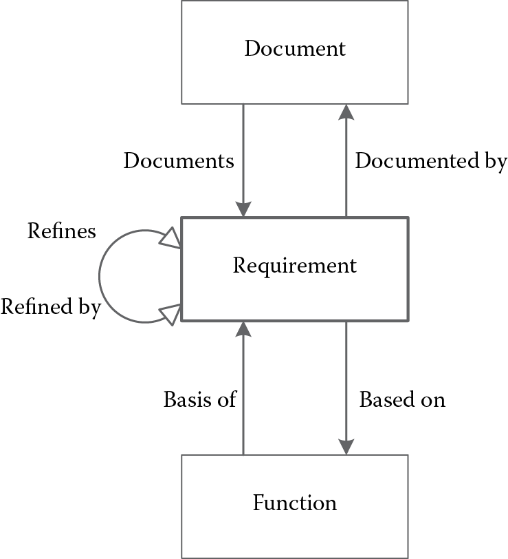
The purpose of requirements management is to assure a well-documented requirements body, recording the necessary information pertaining to each requirement, including its sources, origins, types, rationale, and TPM, and establishing the integral hierarchical structure among the requirements, to trace, verify, and meet the needs and expectations of its users, customers, and internal or external stakeholders. As part of the project planning efforts, requirements management begins with the analysis and elicitation of the objectives, the constraints of the systems, and the missions of the organization. After requirements are collected and initially analyzed, requirements management then provides planning for requirements so that they can be translated and verified in the design, standardizes the format, and records the attributes for each requirement, integrating requirements with the organization and documenting the relationship with other information delivered against requirements. For example, a lower-level requirement refines the higher-level requirements, an external file documents the original sources of the requirement, and all requirements are the basis for particular system functions.
3.5.2 Why Requirements Management?
- Systems engineering is requirement driven; requirements are needed throughout the whole system design process and even the life cycle. System requirements need to be retrievable at any point of the system design. For a large, complex system, it is not uncommon that the volume of the requirements becomes very large; it is unsurprising to have tens of thousands of requirements collected in multiple levels and categories. It is hard to record and manage these large numbers of requirements simply using paper documents. With large volumes of requirements and complex relationships between requirements—and between requirements and other system elements—it is not possible to depend on simple methods such as paper documents or the human memory to reliably manage the requirements; database-based systems management tools are needed to manage the tremendous amount of information related to requirements, so designers can be released to focus on the design activities. A well-selected systems requirements management tool can significantly increase the efficiency of the system design project, thus saving time and money for the design.
- From the nature and sources of the requirements, it is not uncommon for a large, complex project for requirements to undergo a constant modification process. Changes may occur at any stage of the system design; as we mentioned in Chapter 2, changes can be frequently initiated for a number of reasons—for example, trying to incorporate a new technology, the customers have changed their needs, a new design error is identified, a new environment is required, there are new laws/regulations, and so on. For most of the time, making the changes themselves does not involve too much difficulty; it is the impact of the changes that causes a lot of problems. As we know that system design is driven by requirements, the interrelationships between the design elements are very complicated; making a small change in one can have a significant domino effect: it could cause a series chain reaction and have a great impact across the system’s hierarchical structure. The process of implementing the inevitable changes must be formalized and strictly controlled. Most of the contemporary requirements management tools are computer software based in a database structure; thus, they can easily determine the related system elements and their relationships, so that a change proposal will impact within very little time, significantly reducing the time and effort required to prepare the change implementation, thus reducing the cost involved. Requirement management has been proven to be the most effective way for implementing changes related to the design project.
- Requirement management provides requirement traceability. Traceability is one of the key characteristics of MSBE. In the context of systems engineering, traceability refers to
- [the] ability to describe and follow the life of a requirement, in both forward and backward directions (i.e., from its origins, through its development and specification, to its subsequent deployment and use, and through all periods of ongoing refinement and iteration in any of these phases). (Gotel and Finkelstein 1994)
- Requirement traceability is concerned with the bidirectional relationship between systems requirements, and the evolving relationships between requirements and other system elements, such as system functions and components. Traceability is one of the most important factors to ensure the rationality of the system design; among hundreds or thousands of design activities and efforts, traceability makes sure all these activities are conducted in a well-planned and rational manner. Traceability is one of the most important reasons that requirement management is necessary. As mentioned in the requirement collection section (Section 3.3), system requirements come from various sources and in various formats; during the system life cycle, system requirements will undergo various evolutionary stages, and, eventually, all the requirements will be fulfilled through some kinds of system functions, with some components. During the process of translating requirements into the final system physical models, we want to make sure that (1) all the requirements have been addressed at least once by some system elements, functions, or components; and (2) any design decisions or components have a reason or origin for that decision. System design usually takes months, even years; during the long transition period, we want to document every single change and evolution for each of the requirements, to ensure that design follows the right track. Maintaining such a traceability relationship also facilitates the verification process in the later stages. We want to make sure there are no so-called orphan requirements that are not supported by any design components. As the name indicates, traceability traces each requirement throughout the life cycle of the system. As one of the most important functions in the requirements management tool, each requirement is documented and its relationship within the body of requirements and between other system components will be established and recorded. For example, within the requirement body, high-level original requirements may be refined by detailed lower-level requirements that are most likely derived from design teams or decision-making models (sometimes this is called horizontal traceability, since they occur within the requirement body itself); every requirement is a basis for at least one system function, and documented by some external sources (or vertical traceability). In the next section, we will give an example of how to use CORE by Vitech Corporation to develop this relationship. One has to keep in mind that these traceability relationships are usually bidirectional. For example, high-level requirements are refined by lower-level requirements; at the same time, lower-level requirements refine the high-level requirements. Which term to use is dependent on the perspective in which the traceability relationship is looked at. Traceability is documented using the relationship links within the requirement management tool, and these are attached to each requirement for the lifetime of the system. Traceability can be presented by means of a traceability matrix, a hierarchical flow chart, reports, and tables, based on the needs of the analysis.
3.5.3 Requirements Management Using CORE
3.5.3.1 Requirements Management Software Tools
There are many requirements management software commercially available; some of the most popular ones include Rational DOORS and Rational RequisitPro by IBM (previously DOORS by Telelogics), and CORE by Vitech Corporation. For a complete list of the requirements management tools available, please refer to the INCOSE requirement management tool survey, sponsored by the INCOSE Tools Database Working Group (TDWG). The list is published and constantly updated on the INCOSE website (http://www.incose.org/productspubs/products/rmsurvey.aspx). All these tools are based on the fundamental features of requirements management, yet offer different focuses on specific systems or aspects. For example, some are optimized for software systems, and some are configured for easier compliance with government contracts and projects, such as the Department of Defense Acquisition Framework (DoDAF). Regardless of the differences between these tools, they are similar in terms of basic capabilities and features for requirements management. Learning to use one tool will make it easier to transfer to another tool at a later time.
Here, we use CORE (version 9) to describe the basic steps of how the requirements are documented and managed. CORE is developed by Vitech Corporation, serving the systems engineering community since 1992. CORE is more than a requirements management tool; it is a fully integrated model-based approach for collaborative system design, designed by systems engineers. According to Vitech, CORE provides a solution to synchronize requirements, analysis, and architecture, to maintain consistency, reduce risks, and to deliver both technical and management insights to the system design. CORE provides a comprehensive method of tracing requirements throughout the design stages and easily enables designers to build different systems models (such as functional or physical models) based on the designers’ need for a better understanding of the dynamics of the system. CORE provides basic simulation features for the system functions, and is capable of producing on-demand documentation, graphs, and charts automatically in various output formats. CORE provides a university version of the software for instructors and students to download and use at no charge. CORE is compatible with the Windows operating system; it applies a typical Windows style of interface with menus and toolbars. It is relatively easy for anyone who has Microsoft Windows experience to learn to use the software.
As mentioned in Chapter 2, CORE uses a system definition language (SDL) to specify the system and its elements. SDL is a formal structured language using standard English to define the system structure. It is closely linked to and highly resembles the systems concepts, as described in Chapter 2. SDL is built on an element-relationship-attribute (ERA) schema, augmented by graphical structures with semantic meanings.
- Element: An element in CORE corresponds to the design objects/entities. For example, requirements, functions and components are all elements. An element is defined by using an English-language noun.
- Relationship: A relationship defines a link between two elements; it is a binary, two-way relation between two design elements. For example, requirement X is a basis for function Y, and by the same token function Y is based on requirement X. CORE establishes and maintains this two-way communication link automatically once one direction of the relationship is specified by the user.
- Attribute: An attribute is associated with an element; it defines the element further by specifying its critical properties. Attributes are like adjectives modifying nouns (elements); they are defined together with the element. For example, a requirement’s name, number, and type are all attributes of the requirement element.
The ERA structure comes naturally for system requirements management and analysis, as most of the management tools are based on a database structure. This has made many other features simpler, such as searching for specific elements by attributes, or producing relationship charts.
In the next section, we will use a set of sample projects to illustrate the application of CORE in requirements management.
3.5.3.2 Requirements Management Example Using CORE
Figure 3.5 illustrates a sample requirement element in CORE.

Sample requirement element dialog window in CORE 9.0. (With permission from Vitech Corporation.)
In CORE, requirements can be manually inputted or, if there is an external document, such as a Microsoft Word document, CORE allows the user to extract those requirements directly from the document, so that the user does not need to type them in. This greatly reduces the workload, as many organizations have already collected and documented the original requirements; so, an importing tool in the software is important, not only for the purposes of efficiency, but also, it minimizes the chances of making errors during the transition process. Importing from the original document is a must-have feature for almost all requirements management software. Here, we use CORE to illustrate the steps of extracting the requirements using Document Parser; it is assumed that the features of other software would be similar.
Document Parser is user friendly and efficient for importing requirements directly from a document; it will recognize the statements that contain “shall,” “will,” or “must” from the text and automatically organize them into different requirement elements, which makes it easy for designers to review and edit them. It has also the ability to link to the “Document” elements where the original document is linked, thus facilitating the establishment of traceability among elements. To use “Document Parser”, click on “Tools” from the main menu and then choose “Document Parser”. Load the document file that you want to import; the file will be loaded into the left-hand pane in the Document Parser, as seen in Figure 3.6.

Using Document Parser, the text from the loaded document can be extracted directly into any class of elements. The example in Figure 3.6 illustrates parsing the requirement class from the document; select the “Requirement” class from the class drop-down menu and click on the Document Parser icon from the toolbar to parse the document into requirements. All the requirements recognized are marked and numbered, and other statements are marked as “debris” to separate them from the requirements. These debris statements may contain text that is applicable for refining the requirements. For more details, readers can refer to the CORE user manual (guided tour) and resource library at www.vitechcorp.com.
Figure 3.7 illustrates a possible relationship map for a requirement.
3.6 Summary
In this chapter, we examined systems requirements in greater detail. As mentioned many times in Chapter 2, requirements are the driving forces of systems design; spending time and effort to develop a good complete set of system requirements can save designers time, cost, and effort in the long run. In this chapter, the syntax of the requirement was defined and the nature of system requirements and their categorization were given in greater detail. Commonly used categories for requirements include functional requirements, performance requirements, constraint requirements, and verification requirements. The characteristics of a good requirement were given to show how to write a good requirement. Generally speaking, a good requirement shall be correct, complete, clear and precise, consistent with other requirements, verifiable, and traceable. Some general guidelines may be utilized for writing requirements; this was followed by several examples of well-written requirements.
In the second section of this chapter, we reviewed the techniques for capturing requirements, including the sources of requirements, the RFP structure, user interviews, surveys and questionnaires, observations, study of documents, standards, critical incident/accident reports, and the study of similar systems. Each technique was reviewed in detail, and their advantages and disadvantages were presented, for us to use the right technique for the right set of requirements.
A large portion of the chapter was devoted to the methods and models for RA. Major activities in RA were reviewed, and three models that are commonly used in RA were presented, including affinity diagram, scenarios, and use cases, and finally QFD. For each of the techniques, examples were given to illustrate the application of the technique in RA.
In the last section of the chapter, requirement management was briefly introduced. Requirements management is essential for the success of the system design, as it efficiently organizes the large volume of requirements, enables an effective and controlled process for requirement changes, and, most importantly, provides traceability within the system life cycle, which makes design efforts more effective and easy to understand. Examples using CORE were given at the end to show how a software tool can be utilized to implement management of the requirements.
Problems
- What is a requirement? What are the characteristics of a good requirement? What are the sources of a requirement?
- What is an RFP? What is an SOW? What are the purposes of the RFP and SOW?
- What is requirements analysis (RA)? What are the major methods involved in requirements analysis?
- Describe the QFD approach. What is the major benefit of using the QFD approach? In your opinion, what are the limitations of the QFD method?