CHAPTER
5
The content life cycle
If all things change, then change is constant; and total chaos is complete order!
Amid the transitional chaos of the new broadcasting universe, the media life cycle remains constant. Very simply put, content must be created, assembled, distributed, and consumed. This will never change.
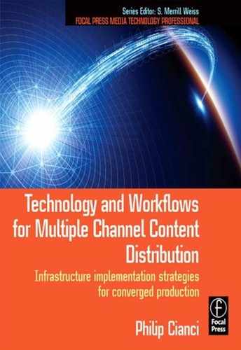
Any media business can be described in four phases, as shown in Figure 5.1.
To use the book publishing industry as an example, the four phases are as follows:
![]() Creation: Copy is written, photos taken, cover art designed.
Creation: Copy is written, photos taken, cover art designed.
![]() Assembly: These creative elements are assembled into a book.
Assembly: These creative elements are assembled into a book.
![]() Distribution: The book is shipped to outlets, advertised, and promoted.
Distribution: The book is shipped to outlets, advertised, and promoted.
![]() Consumption: Someone buys and reads the book.
Consumption: Someone buys and reads the book.
Technological advances play a major role in each of the processes and workflows required in each phase. New technology may open new opportunities. The cell phone as a means of video consumption, the Internet as a distribution channel for network TV programming, file-based workflows during the assembly phase, and images captured using modern charge coupled device (CCD) cameras have all had a positive impact.
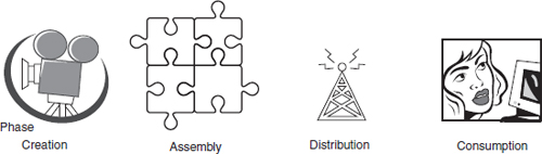
FIGURE 5.1
The four-phase content life cycle
This chapter will discuss the flow of content through each of the four phases. It is helpful to break down the broadcast chain into these phases in order to better understand the workflows, processes, and technology particular to each phase.
The broadcast TV chain will be used to establish a baseline, and then we'll look at how repurposing content for or from multiplatform, particularly the Internet and handheld devices, impact each phase in the content life cycle.
DISRUPTION OR EVOLUTION?
Journalists often use the term “disruptive” to describe the recent state of the media business. The transition to digital media has fundamentally transformed broadcast operations. Nearly all production processes are digital; only legacy content remains as analog form. Eventually, even this will all be converted to digital.
Rather than continuing to be disrupted, the media industry is adapting and is really at a pivotal moment. The three-screen universe is about opportunity. And TV broadcasters are in the pole position as the race begins. It may be fashionable to herald the demise of television, and in some ways this may be true. News consumption has definitely migrated away from television and newspapers to the Internet.
The Super Bowl will always be a mass audience event. I may watch the pregame show on my cell phone while I am on a train just to get commentary from my favorite analysts. But I, along with millions of others, will arrange my day so that I can be in front of my HDTV at kickoff time. I'm willing to wager that many will pay to see the game in a movie theater in 3D, as it was presented at an invitation-only test event in 2009. I can't imagine that anyone would choose to watch the game on a 2.5 inch LCD screen when a better alternative is available.
Television broadcast signal chain
The flow of content through the TV air chain was once relatively straightforward: remote backhaul, studio cameras, and VTRs or telecines were the sources; the program control room (PCR) and master control room (MCR) switched and assembled program elements; this “program” signal modulated a carrier and was transmitted to a receiver. This was and, on a fundamental level, still is the broadcast air chain.
As with just about all aspects of life in the new millennium, today, with the digital communications revolution, each phase of the content life cycle has broadened, expanded, and become exponentially more complex.
Figure 5.2 shows how content moves through each phase of the TV operations chain. It closely adheres to the four phases of the content life cycle.
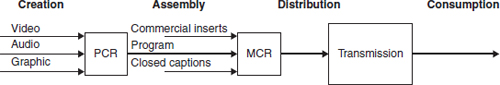
FIGURE 5.2
The content life cycle for television
THE CROSS-PLATFORM MEDIA LIFE CYCLE
With 100 HD channels available and so many complaining that there is very little worth watching, compelling content is the key to attracting viewers. More and more people are turning to TV simulcasts, reruns, and video over the Internet. Original programming is being produced for the Internet, and a few of these shows have migrated to television. Specialized content is now being produced for cell phone delivery. Sports, weather, and news alerts can automatically be sent to your PC or cell.
From one perspective, television can be considered the driver of content production for multichannel distribution. On the other hand, the low cost of entry to Internet broadcasting has enabled anyone with the guts to create content and to be able to instantly get it out to the world.
Making money from new media channels is another story. All broadcasters will admit that alternate distribution modes, regardless of all the hype, have yet to be profitable. As NBC Universal CEO Jeff Zucker put it in early 2008, “Our challenge with all these [new-media] ventures is to effectively monetize them so that we do not end up trading analog dollars for digital pennies.”
“Produce once and distribute everywhere” is the mantra. This requires an agile BOC infrastructure where format conversions, compression, packetization, and modulation occur as automated processes that are “aware” of the distribution channel. Content is now regularly reformatted for the Internet, PDA, cell phones and, by a few innovative organizations, mobile DTV.
Yet with all the talk of disruption, the content life cycle still applies to all new media scenarios. Whether individually, or collectively, content is still created, assembled, distributed, and consumed. It is a powerful model to keep in mind as infrastructures evolve to support all three screens: TV, PC, and handheld.
Figure 5.3 expands the four phases to other delivery channels and delivery devices. As you can see, there are many common processes.
Once again, the big-picture view is an oversimplification. An infrastructure that supports three screens is within reach. But support of interactive television, enhanced television, gaming, product placement, and targeted, personalized features requires new technology and production techniques. These features are being deployed now in test markets.
FIGURE 5.3
Multiplatform production and distribution and the four-phase content life cycle
The creative phase
Phase one is the creation of content. Storytelling is what the creative phase is all about. Each segment of a news show is a story. Sporting events are unscripted drama. Even a game show tells a story. Compelling graphics can hold viewers’ eyes on the DTV set. Multichannel sound is immersive. And it can be hard to take your eyes off an HDTV image.
Audio, video, and graphic elements—“essence” in contemporary jargon—can be acquired live from a remote site or locally in a studio, produced, and stored in a file or on tape or transferred from film using a telecine machine.
A single NTSC production-based process has given way to multiple format sources. Consider a news show that uses citizen journalists providing HDV, or Internet video, as well as professional SD 480i for an HD news broadcast. Sophisticated graphics and animations as well as 5.1 surround sound are required for aesthetically compelling content. Set design and show performance have escalated to the high production values of an immersive theatrical event.
Let's consider the technology that supports each of these sources.
On the set
Television studio sets have come a long way since the days of Soupy Sales, when scenes were painted on canvas frames and props hung from the woodwork. Today's sets are more like Broadway show or rock concert multimedia productions.Watched any studio origination television lately? Then you've noticed that studio sets have become amalgams of displays, lighting, and virtual elements.
Still, no matter how perfect a digital production and transmission infrastructure might be, no matter how perfectly a consumer device reproduces the data it receives, the quality of the presentation will only be a good as the source.What you see (and hear) is what you get, so you better make sure the source is of the highest production quality.
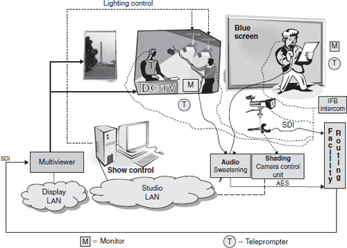
FIGURE 5.4
Functional components of a high-end set, studio, and show control infrastructure
Broadcast engineers need to be aware of the technical requirements of a modern studio environment. Studio technology is now just as complex as any other system in the four-layer BOC infrastructure. The layers within a studio consist of physical components (lighting, displays, and props), media network (control communications and content movement), applications (computer platforms that run show control programs), and security (locked studio and control room doors and control system log on with passwords).
Show control, multivideo displays abound. Systems found in a studio are illustrated in Figure 5.4. Beyond the usual camera control unit, there is the addition of show control, multivideo processors, and other networked equipment installed in computer workstations.
It's all in the telling…
Creativity is no longer limited by technology. With CG, GFX, and animation applications anything is visually possible. The same is true for audio. But one must not lose sight of the storytelling mission. Do the GFXs and sound contribute to the narrative? Does the graphic convey appropriate information that is easily understood? We often hear criticism about implementing technology for technology's sake, to have the latest and the greatest. A similar argument can be made about GFX, visual, and audio effects for creativity's sake.
Studio design
HD studios require meticulous attention to visual detail when building sets and installing video displays and lighting. Today sets are dynamic, made of Plexiglas and metal, and designed in a way that the use of lighting can produce any color and effect desired. These futuristic designs and radiant colors exploit the new capabilities of DTV.
With the increased sophistication of set technology, precise control of all show elements is required. Makeup, lighting, set design, show control, and set construction (either real or virtual) are all integral parts of twenty-first century TV production and have evolved to meet the requirements of HD.
Make up
There is a story that has circulated since 1998 when the first HD broadcasts were going on the air. An anchorwoman was overheard as being totally against HDTV because she thought it would bring out every blemish on her face.
Psycho visual tests have shown that the visual perception is extremely critical of fidelity in skin tones. Proper application of makeup is so important to HDTV production that the Television Academy of Arts & Sciences has presented seminars discussing HD make up techniques.
Test scenes available for camera calibration include images of real people representing the gamut of skin tones. In addition, modern HDTV cameras have built-in skin-tone correction circuits.
So, contrary to the anchorwoman's worries, new airbrush HD makeup techniques, improved lighting, and electronic skin-tone correction actually make talent look better than they ever did before!
Lighting and show control
Lighting effects that accentuate the dramatic action have been an integral part of studio production since day one. Color media technology has progressed from simple colored gels to color temperature-balanced correction filters; lighting control has gone from manual operation to sophisticated computer automation.
A distinction must be made between overall control and the control of individual resources. Industry jargon uses two terms: “entertainment control” and “show control.” Entertainment control systems operate a particular type of resource such as lighting, sound, video displays, rigging, or even pyrotechnics. Show control links together the various entertainment control systems.
Two serial communication protocols are predominately used for lighting and show control, DMX512 and MIDI show control (MSC). Connections are made over USB, musical instrument digital interface (MIDI), or LAN.
A worldwide standard, DMX512 is used by lighting consoles to send information to dimmers. Intensity levels, color changers, automated light sources, and smoke machines use the DMX512 protocol. Information is sent using 8-bit digital codes. Up to 512 devices at unique addresses can be controlled over one cable. Motorized lights require fine adjustment than 256 levels so more than one DMX address is used to extend the range to 65,536 levels.
MSC is an extension to MIDI and uses system exclusive commands. MSC can synchronize lighting cues, music playback, set element motion control, and other show control devices. Commands are accurate to within 1/30th of a second (frame accurate). Systems can be used to control lighting and sound cues to create a sequence that will be identical every time.
Field origination
A remote broadcast truck, frequently an 18-wheeler, is actually a mini-broadcast operations center up to the production control room. A completely produced program is backhauled to the operations center. There, commercials, logos, and closed captions are mixed with the clean program feed.
Electronic newsgathering (ENG) vehicles are smaller than broadcast trucks, often vans. Production capabilities are not as elaborate as a broadcast truck. However, ENG vans usually have transmission capabilities, including a microwave/satellite dish on the roof.
Audio and video formats
Two other issues to consider that are relevant to the creation phase are audio and video acquisition formats and metadata.
Digital audio and video come in more than one flavor. Format conversion is to be avoided, but invariably will occur. To enable efficient workflows, a house-standard audio and video format is decided upon. Many broadcasters have found that by converting all incoming content to the house format, conversions can be kept to a minimum, with subsequent simplification of workflows and reduced expense for conversion equipment. Figure 5.5 illustrates the method.
Unfortunately, in a digital media environment, once content has been converted into a file, the ability to read a label to identify content disappears. Content must be tagged with metadata as it is created and ingested into the asset management system. A major challenge facing the broadcast industry is to be able to trace digital content via metadata in either direction, through the four phases of the content life cycle.
With production facilities and processes being spread across the country and around the world, new methods of distributed real-time collaborative capabilities are being developed. These content delivery networks are dedicated infrastructures systems with guaranteed data rates. Successful experiments have been delivered in uncompressed HD.
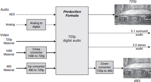
FIGURE 5.5
Conversion of all incoming audio and video to house format
Multiplatform creative
As has just been described, producing content for television is a huge undertaking. Unless you've actually been in a studio and toured the technical operation of a facility, it is difficult to get an idea of just how large-scale it is.
To be a live Internet broadcaster, all you need is a computer, a webcam, and a microphone; anyone can do it. PC desktop software enables a person of any skill level to create their latest epic with the ease of drag-and-drop interaction and post it to YouTube. Internet radio broadcasting is even easier: just convert to MP3 and stream away; many hosting services are available for reasonable fees.
However, creating and preparing broadcast-quality content for distribution over multiple channels poses many technical challenges. Presentation issues top the list: audio and video must be converted to the proper format for the reception device. Compression issues and reception device compatibility issues add to the complexity.
For example, HD video uses pixel grids that are either 1920 × 1080 or 1280 × 720. Computer monitors do not natively support these formats: 1920 × 1200 or 1280 × 768 is as close as they get. In addition, widowing will require format conversion, and not a single cell phone display has attained the HD level of native pixel-grid resolution.
Similar limitations apply to 5.1 surround audio when it accompanies content delivered to a PC or cell phone. Sure those little earphones are convenient, but would you listen to them at home if you had the choice of connecting your MP3 player to your home audio system?
Format conversion is a core operation in the workflow that repurposes content for another platform. HD content will have to be scaled down, cell phone content scaled up, and Internet content up for television and down for cell phones. Audio presents similar conversion requirements: 5.1 to 2.0 stereo; mono or stereo to 5.1. Many flavors of conversion must be supported, especially where the sources of content are Web-friendly formats like JPEGs, MOV, or AVI files.
User-generated content has become ubiquitous on the Web. This impacts quality. A viewer on a PC is usually more interested in the content rather than the presentation quality. Less than the highest production values are sufficient. This is also true of TV news: getting to air first and breaking a story is more important than getting the perfect shot.
The moral of our story? Quality matters. For video, viewing distance can mitigate resolution issues; the eye cannot see HD detail on a cell phone, even if the phone were able to display it. But once the novelty of watching a rerun of your favorite TV show on your cell phone wears off, odds are you will DVR the next episode.
Program assembly
In the program assembly stage—the second phase of the content life cycle—audio, video, and graphics elements as well as edited segments and animations are assembled into a program and passed on to the distribution channel. In the analog era, when a program left master control for transmission, it was a composite signal ready for modulation on an RF carrier. In the digital age, it is a stream of data packets.
In the analog TV system, audio and video timing was innate; the program arrived preassembled. The receiver simply had to demodulate the signal and then present the audio and video.
This is not so straightforward in the DTV universe, where assembly of program elements is a lot more complicated. The audio and video exist separately as data packets and do not have an innate timing relationship. Audio and video compression introduces variable delays. Therefore, in addition to program content, assembly instructions and timing information must be sent in special packets in the program.
Content flow
Integration of audio, video, and graphics elements into a program is done primarily in the PCR. This step can be considered the doorway to the assembly phase. Insertion of logos, ratings, and closed captions, as well as signaling cues for downstream automated commercial insertion, happens in the MCR.
This is more or less the same signal flow as in the analog domain, right? Well, not exactly. First off, the audio and video are carried in an SDI stream. Audio channels may be embedded in the horizontal blanking areas (HANC) of the SDI signal.
But the biggest difference is that after master control the audio and video must be compressed. This encoding process will turn the raw digital audio and video into elementary streams (ES) and then packetized elementary streams (PES). Any implied temporal relationship between the audio and video that existed in the SDI signal is lost. Audio and video packets are marked with a presentation time stamp (PTS) for use by the DTV receiver. The PES packets are further divided into 188-byte packets and multiplexed into an MPEG-2 transport stream (TS).
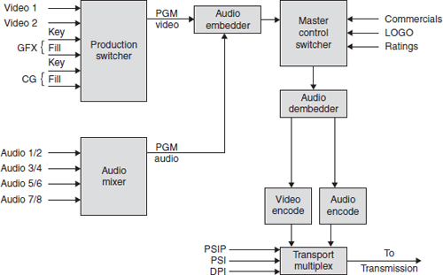
FIGURE 5.6
Assembly phase for TV operations
Assembly instructions are multiplexed into the TS too. The technique depends on the DTV standard and the delivery channel. MPEG-based systems such as digital video broadcast (DVB) use the MPEG-2 protocol of program-specific information (PSI) while the ATSC includes MPEG tables but adds A65 program-specific information protocol (PSIP). Downstream commercial insertion is made possible by digital program insertion (DPI) splice points and cue tones that are added to MPEG-2 TS during creation of the emission multiplex.
Figure 5.6 graphically presents an overview of the assembly of a DTV program.
In the PCR and MCR, insertion and switching of audio, video, and graphics is a real-time activity, done on the physical layer, with SDI and AES being the primary essence format. Content may have been moved to playout servers over the media network in compressed format, but when taken to air, it is decompressed back to SDI and AES for switching operations.
A production switcher, loaded with macros, controls the firing of the playout servers. Command, control, and management communication occurs over a combination of LAN, RS-422, and general purpose interface (GPI). Sometimes a dedicated device is required to convert from one control format to another, say IP to GPI.
Applications running on computer platforms “fire” playout of graphics, clips, and other content sequences. For a live broadcast, the director will command the firing of a command sequence, with the rest of the segment controlled by automation.With a long-form program, with all content and interstitials on tape or servers, a redundant automation system, timed to reference signals, controls playout to air.
Some graphic elements will be assembled on the fly by a computer-based playout application. GFX, audio, and text elements will reside in a database and be assembled into templates.
The result must be seamless assembly and presentation of program elements. There are no second chances.
DTV audio and video compression
During the compression process, audio and video is coded for transmission in the appropriate codec format. In the ATSC terrestrial DTV system used in the United States, MPEG-2 is mandated by law in Part 47 of the FCC rules and regulations. Cable, DBS, and telco DTV broadcasters are free to use any codec they choose.
Perceptual compression is an enabling technology for digital transmission and production. It takes a compression ratio of over 50: 1 to squeeze 1.5Gbps HD content into a 20 Mbps MPEG-2 TS pipe. Audio is no bargain either. Raw PCM audio is about megabit per second and six channels, even with the limited frequency response of the LFE channel, and will be over 5Mbps. The total bit rate for video and audio will be reduced to less than 512 Kbps 5.1 surround sound for transmission.
Since compression format conversion is such an important part of the content repurposing workflow, a more detailed discussion is deferred to Chapter 9.
Beside the basic issue of conversion, as mentioned earlier, variable delays in the process of compressing audio and video separately must be accounted for. Conversion systems, and PCR and MCR switchers, as well as many other pieces of audio and video equipment, have buffering capabilities that can be used to restore audio and video timing.
The MPEG-2 transport stream
The final step in the ATSC DTV assembly process is the multiplexing of audio, video, and data packets into a stream of no greater than 19.39 Mbps. The method is specified in MPEG-2 and called a Transport Stream.
The process begins with compression and concludes with the production of transport packets as shown in Figure 5.7.
MPEG-2 transport packets are 188 bytes in length and consist of two fields, as shown in Figure 5.8. The first 4 bytes are the header; the remaining 184 are the pay-load. Depending on the setting of particular bits in the header, the payload will be identified as consisting of audio or video or the presence of adaptation fields with additional information.
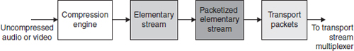
FIGURE 5.7
Processing steps to convert baseband audio or video to transport packets
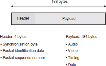
FIGURE 5.8
MPEG-2 transport stream packet structure
Key to locating and identifying the content of packets is the packet identification data, universally referred to as a PID. Packets of audio and video elements for a DTV program each have a unique PID. Each audio and video packet will have a particular PID in its header field that is used to parse the desired audio and video from the TS.
MPEG-2 TSs, as specified in ISO/IEC13818-1 is limited in the ATSC standard to data rates of 19.39 and 38.78 Mbps.
Assembly instructions
DTV assembles audio, video, and data elements for presentation at the receiver; they are transmitted without any innate temporal relationship. In fact, video frames are sent out of order.
The only means of identifying a TS packet is its PID. But this information alone is not sufficient to locate the audio, video, and system timing (clock) within the TSs that are necessary to assemble a complete program.
System timing: the system time clock
Because of the lack of an innate timing relationship between audio and video packets, a mechanism is necessary to insure that the original image and sound timing is recreated when the image and sound are presented. This is accomplished by a mechanism known as the system time clock (STC). STC packets that include a “wall clock” are part of the information in all DTV systems that use MPEG-2 TSs.
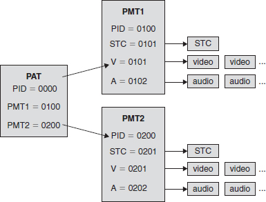
FIGURE 5.9
MPEG-2 program-specific information (PSI) tables
MPEG-2 assembly
MPEG-2 provides tools to accomplish program assembly. These are in the form of “look-up” tables found in what's referred to as PSI.
Program-specific information
PSI is a set of tables that facilitates program construction from TS packets. The program allocation table (PAT) and program map table (PMT) identify the PIDS for program elements.
As Figure 5.9 illustrates, the PAT always has a PID of 0000. This allows it to be parsed from TS without confusion or ambiguity. The PIDs of all the PMTs located in the TS are identified. There may be a single program or multiple programs and referred to as SPTS, single program TSs or MPTS, multiple program TSs, respectively.
Using the PIDs supplied in the PAT, the PMT of interest is located and then parsed to reveal the PID of the STC, video and audio packets. The decoder now simply demultiplexes the video and audio packets and sends them on to the appropriate buffer associated with decompression codec.
ATSC program assembly
MPEG PSI failed to meet the needs of American broadcasters, who needed a means to maintain long cultivated audience channel brand and number associations. They also required a method for simple navigation among multicast channels.
Program and system information protocol
One of the primary differentiators between analog television and digital television is the capability for digital systems to deliver data in addition to the audio and video. This includes the mandatory carriage of Programming and System Information Protocol (PSIP) data, ATSC A/65. PSIP data includes program descriptions, ratings information, and closed captions. Presence of PSIP data is an FCC requirement.
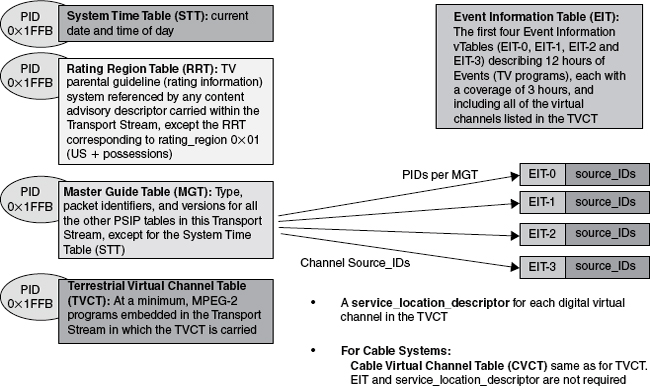
FIGURE 5.10
Required PSIP tables
Figure 5.10 illustrates the relationship and function of the required PSIP tables.
When the presence and content of PSIP data is carefully considered, one potential application of program descriptions found in the event information table (EIT) is that it may be used by the asset management system for classification and search. By storing the EIT and linking it with the program, the EIT can also be used when a program is rebroadcast. Similarly, RRT (ratings) data can be linked to the audio and video content and used when the program is repurposed, ideally, in an automated workflow.
If all this information were abstracted one layer above the textual implementation of EITs, RRTs, etc., and stored in a database, this database could be associated with the program content and used for repurposing in creative and unique, broadcaster-differentiating ways. This is the idea behind media objects and content wrapper techniques.
PSI and PSIP
An ATSC transmission is required to carry MEPG PSI and PSIP tables. The information must be consistent in both. Figure 5.11 illustrates the relations between methodologies.
Transport stream packet multiplex
The interleaving of audio, video, assembly, and timing packets is a form of multiplexing. Strict multiplexing sequentially alternates input data: the data is output at a rate that is the input rate multiplied by the number of data inputs.
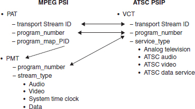
FIGURE 5.11
The relationship between MPEG PSI and ATSC PSIP methodologies
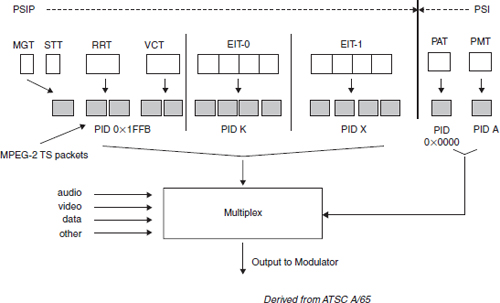
FIGURE 5.12
Audio, video, and PSIP multiplex
MPEG-2 multiplexing is not a strict multiplex. Video packets greatly outnumber audio packets; audio packets occur more frequently than PSIP or PSI packets. This underscores the importance of the PID. Packets are parsed from the stream based on their PID. Figure 5.12 is a visual representation of packets that are included in a TS multiplex.
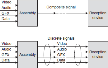
FIGURE 5.13
Assembling content for multiple delivery channels
Element assembly for multiple platforms
Assembling content elements for more than one distribution channel is complicated. Rather than brute force use of distribution channel-specific independent work-flows, an elegant solution that integrates production resources and produces format ready for distribution over each channel is preferred. This approach will save capital expense on redundant equipment, it will reduce production time, and it will enable more to be done with existing staff.
The basic method strives to leverage audio, video, graphics, and data elements created in phase one. Two basic techniques can be applied to assembling content for delivery.
Compositing takes audio, video, and graphics information and produces a single, integrated indivisible stream (or file); this is similar in concept to analog television. The discrete technique delivers audio, video, and data elements independently; this is similar to an MPEG-2 multiplex.
Figure 5.13 is a functional diagram that compares the two techniques. The selection of which method is employed over a channel defines the presentation characteristics and feature set available in the reception device.
Programmatic assembly
As one might expect, with the Web being a computer- and software-based technology, software programming is the key to Web page assembly. Instructions for Web presentation are defined in the programming code used to create the page.
HTML
Hypertext markup language (HTML) is the foundation of Web page authoring. Although many other improved Web-oriented programming languages continue to appear, HTML has persisted. It is simple to use to create Web pages, because there are no subtle syntax or implementation nuances. With its simplicity comes reliability.
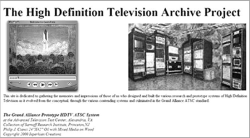
FIGURE 5.14
Rich media HTML Web page with video, audio, jpeg, and text
HTML may be simple, but sophisticated multimedia Web pages can be created with it. Figure 5.14 is produced by Listing 5.1. This relative body of HTML code implements audio and video playback as well as the usual set of Web site features.
For TV broadcasts repurposed for the Web, a choice needs to be made as to whether to run the broadcast exactly as it has gone to air, or use a clean feed and mix graphics via the page code.
Cell phones offer no choice. Graphics and data will not be legible, and must be managed separately from the program stream. The only caveat is that screen resolutions for handheld devices have reached pixel-grid dimensions that approach video-cassette levels of presentation quality.
The point of this is that if audio, video, graphics, and data are kept independent of each other, the assembly phase can arrange for transmission of each element in a way best for the delivery channel.
Compression requirements for each distribution channel and target device vary. Meeting the optimal data rate raises quality issues that must be addressed. Frame rate influences data rate.
For example, MPEG-2 HD video is compressed to about 12 Mbps for over-the-air delivery. Few ISPs can guarantee sustained delivery of this data rate. Therefore, MPEG-2 video will not make over the Internet. Even an AVC or VC-1 codec, which reduces the bit rate for HD to 6 Mbps, will not enable HD over the Internet.
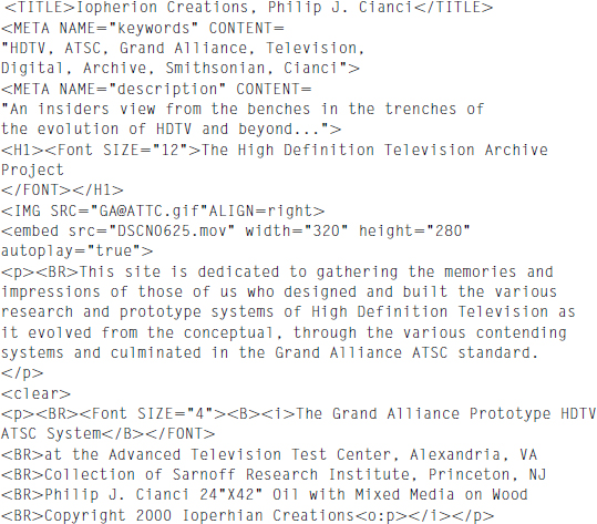
LISTING 5.1
Source HTML for Web page in Figure 5.14
Assembling content for cel phones and handheld devices
Programming languages have been developed specifically to ease the use of audio and video on the Internet and for delivery of content to cell phones. Synchronized multimedia integration language (SMIL) is one such language.
SMIL
SMIL is a W3C-recommended XML markup language for describing multimedia presentations. It facilitates the presentation of text, images, video, and audio. A SMIL presentation can contain links to other SMIL presentations. Markups are defined for timing, layout, animations, visual transitions, and media embedding.
SMIL files are text files, similar to HTML. Developers have a variety of tools they can use to create SMIL: dedicated authoring software and SDKs, XML editors, or text editors.
The Open Mobile Alliance (OMA) multimedia messaging service (MMS) specification defines the use of MMS SMIL for handheld applications. The benefit of using this SMIL profile is that all OMA-conforming MMS devices will be able to understand and play a presentation.
The 3GPP suite of specifications defines the 3GPP SMIL profile. This SMIL profile is designed primarily for streaming purposes (and is defined in the 3GPP Packet-Switched Streaming Services version 5 specifications, also referred to as the PSS5 SMIL profile). The 3GPP specification also permits use in MMS. Although 3GPP SMIL does not include all the features of SMIL 2.0, it allows much richer content to be created.
Distribution
HD/DTV distribution began over the air and now includes cable, satellite, and telco delivery to the home. Legal and business issues regarding retransmission consent come into play defining how terrestrial broadcasts can be distributed over these other technologies.
The Web has been a Wild West for TV programming. Broadcast content often finds its way to video sharing and social Web sites. Even the most rudimentary consumer media management and editing software includes the ability to effortlessly upload content to a Web site. But before we talk about the newest content distribution channels, let's look at the development of communications distribution from the telephone on forward.
Content distribution
When telephone was invented in 1876, telegraph lines provided a preexisting infra-structure. As a result, telephone systems were immediately operational: there was no need to build a new distribution channel from scratch. This scenario would be repeated with the consumer adoption of the World Wide Web in 1995.
Although primitive by today's standards, telephone technology was the first to use communication principles we still use today. The conversion of sound waves in air to electrical signals by a transducer (microphone) established the fundamental technique of capturing the world of our senses in an analogous manner to electricity.
Analog vs. digital modulation
Analog modulation varies the amplitude, frequency, or phase of a high-frequency sine wave. Advanced techniques can use combinations of these basic forms of modulation. The term “analog” refers to the information that is to be conveyed. Analog signals produce variations in a step-less continuum of voltages.
Digital modulation applies discrete voltage levels to the RF carrier, creating characteristic patterns of steps or “constellations” when viewed on appropriate monitoring equipment. In actuality, modulation is always an analog operation, even when the information is in the form of digital symbols.
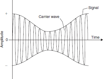
FIGURE 5.15
Amplitude modulation of a carrier wave
Amplitude modulation
Just after the turn of the twentieth century, Reginald Aubrey Fessenden invented a high-frequency alternator that produced a continuous radio wave. It was a significant improvement of the intermittent spark-gap generators that had been previously used for wireless transmissions. Fessenden invented a way to modulate the amplitude of radio waves, the enabling technology for AM radio (see Figure 5.15).
Amplitude modulation is transmitted as a sky wave: it reflects off the earth's ionosphere. The ionosphere is a layer of charged particles, theorized in 1902 by Arthur Kennelly and Oliver Heaviside, and discovered in 1924 by Edward Appleton. This reflection enables AM radio signals to travel great distances. However, changes in the ionosphere at night alter its reflecting characteristics, causing variations in signal propagation distances. Lightning is a source of electromagnetic radiation and degrades an amplitude modulated radio signal.
The invention of the vacuum tube by De Forest improved the system. But it wasn't until Armstrong developed heterodyning that radio transmission became practical.
Carrier radio waves are very high frequencies when compared to audio. This can create difficulties in accurate transmission of information if modulation is directly applied. Heterodyning is a technique that first modulates an intermediate frequency (IF) with the signal and then modulates the carrier with the IF containing the audio in the second stage. The technique has been extended to enable use of RF carriers in the gigahertz range for satellite transmission.
With the development of radio broadcasting technology, communications were no longer limited to areas where a physical cable reached. Radio waves propagated freely in space. Broadcasting was quickly monetized. Commercials paid for sponsored programming.
Television makes the scene
With the problem of capturing and broadcasting sound solved, it was only natural for researchers to turn to the sense of sight. By that time, radio broadcasting had become big business. Big corporations had money to spend on speculative R&D projects. AT&T and RCA backed rival inventors Vladimir Zworykin and Philo T. Farnsworth, respectively. When the smoke cleared, the NTSC television standard was established. Parallel efforts in Great Britain by John Logie Baird produced a television system that was on the air prior to WWII.
Although some of the initial systems were electromechanical, NTSC I, the original black and white system in the United States, used all electronic technology.
Analog TV broadcast technology
Compared to radio broadcasting, television was infinitely more complex. Radio consisted of one, relatively low-frequency signal, the human voice is below 3 kHz, while a TV signal had video at 4 MHz rates and the requirement to mix audio into the signal as well.
The introduction of color made matters all the more challenging. Color was conveyed as the difference in phase of the color subcarrier, a 3.58 MHz sine wave.
Different systems, each with variations and improvements, were developed around the world: PAL in Europe, except for France (naturally), which developed SECAM. The systems engineered by these pioneers served the world well for more than 50 years.
Digital transmission
Digital transmission systems consist of two steps. In the first, frequently called error correction and concealment (ECC), the digital data is processed to insure maximum robustness for the intended delivery channel. In the second step, ironically, the digital signal is mapped to an analog voltage and then modulates a radio frequency carrier wave.
Error correction and concealment
Distribution of real-time digital media over RF- and cable-based systems is subject to electromagnetic interference. If a transmission error occurs, lost data cannot be retransmitted. Therefore, a means must be employed to insure robust delivery and reception.
Figure 5.16 illustrates the components that are involved in the ECC step.
As shown, ECC consists of four steps. Each is tuned for maximum resiliency of the intended delivery channel technology.
Channel coding The purpose of channel coding is to make maximum use of channel bandwidth and minimize burst noise errors by spreading data over full channel. This prevents long runs of zeroes or ones.
In the ATSC DTV transmission system, the randomizer generator polynomial is:
G(16) = X16 + X13 + X12 + X11 + X7 + X6 + X3 + X + 1
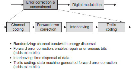
FIGURE 5.16
Distribution phase for TV forward error correction
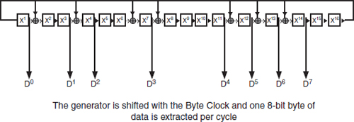
FIGURE 5.17
Channel coding randomizer polynomial (using D flip flop and exclusive OR gates) (Derived from ATSC A/53)
The initialization (preload) to 0 × F180.
Implementation of the algorithm can be accomplished by using a shift register feedback circuit as shown in Figure 5.17.
A shift register has an input, data registers, and an output. The data register in a hardware implementation is similar to latching D flip flop (see, Appendix, Figure B.3). A bit enters the shift register, and as it traverses the chain, is exclusive ORed (XOR, see Appendix B) with the output bit as defined by the generator polynomial terms.
The result is data that has the spectral characteristics and data distribution of random noise. Since electromagnetic noise is usually limited in frequency, this technique reduces the probability that a noise burst will destroy an unrecoverable number of data words because data is distributed uniformly over the channel bandwidth.
Forward error correction Television is real time;if data is corrupted during transmission, it cannot be resent. Forward error correction (FEC) is a means of enabling detection and correction of bad data by including parity information in the transmission. DTV system use Reed-Solomon techniques.
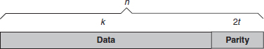
FIGURE 5.18
Data payload with Reed-Solomon FEC parity
The Reed-Solomon encoder takes a block of digital data and adds extra “redundant” bits. Errors occur during transmission or storage for a number of reasons (e.g., noise or interference, scratches on a CD, etc.). The Reed-Solomon decoder processes each block and attempts to correct errors and recover the original data. The number and type of errors that can be corrected depends on the characteristics of the Reed-Solomon code.
Reed-Solomon codes are a subset of binary-coded hexadecimal (BCH) codes and are linear block codes. A Reed-Solomon code is specified as RS(n, k) with s-bit symbols.
This means that the encoder takes k data symbols of s bits each and adds parity symbols to make an n symbol code word. There are n – k parity symbols of s bits each. A Reed-Solomon decoder can correct up to t symbols that contain errors in a code word, where 2t = n – k.
The diagram in Figure 5.18 shows a typical Reed-Solomon code word (this is known as a systematic code because the data is left unchanged and the parity symbols are appended):
Example: The Reed-Solomon code in the ATSC system is RS(207, 187) with 8-bit symbols. Each code word contains 207 code word bytes, of which 187 bytes are data and 20 bytes are parity. For this code:
n = 207, k = 187, s = 8
2t = 20, t = 10
Therefore, an ATSC decoder can correct any 10 symbol errors in the code word: i.e., errors in up to 10 bytes anywhere in the code word can be automatically corrected. In Europe, the DVB DTV system uses RS (203, 187), 2t = 16 resulting in the ability to correct up to 8 byte errors.
Interleaving Added protection against burst noise is accomplished by spreading the bits in each byte over time. The technique is known as interleaving.
Consider a sequence of bytes, A, B, C,…, where each bit is denoted by A0, A1, A2, …. The transmission sequence would be:
A0, A1, A2,…A7, B0, B1, B2,…B7, C0, C1, C2…
A noise burst of 16 bits in length would completely destroy either two bytes or one completely and two partially. Depending on the number of bits per byte that can be corrected, this damage may be beyond the ability of the FEC algorithm to correct.
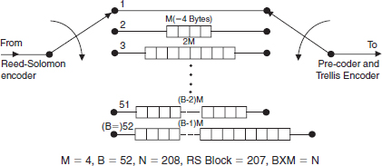
FIGURE 5.19
ATSC Convolutional interleaver (Derived from ATSC A/53)
Interleaving the same sequence produces the bitstream A0, B0, C0, … A1, B1, C1, … A2, B2, B2, ….
If the same 16-bit noise burst damages the interleaved stream, the maximum number of bits damaged in any byte would be limited to two. By spreading the bits out farther, eventually a point would be reached where damaged bytes would be spread such that the damage would be spread over a number of transport packets. This helps to insure that the number of bytes corrupted by channel noise will be within the capability of the FEC implementation.
Interleaving is accomplished by a convolutional technique. Figure 5.19 shows the convolutional interleaver used in the ATCS DTV transmission system.
Bits enter shift registers 1 through 52 in sequential order, moving to the next register when the previous one is full. At the output, bits are read out in a rotating order, always from 1 to 52. This creates a completely deterministic bit pattern. At the receiver the process is reversed.
Trelis coding The final ECC processing step, trellis coding, increases the probability of a symbols occurrence. The technique also maps symbols to analog voltage levels. Figure 5.20 shows the processing blocks of the trellis coding algorithm used by ATSC 8VSB.
Trellis coding is specified by the number of input bits to output bits. In the ATSC technique this is denoted by (2,3); for every two input bits an output symbol of three bits is created.
The result is a reduction of legal locations a bit may occupy. Figure 5.21 shows the method as applied to quadrature amplitude modulation (QAM).
As the figure shows, in the topmost constellation, there are four-bit locations in each quadrant. After trellis coding, as can be plainly seen in the bottom row, only one-bit position is valid in each quadrant. Therefore, the area where a valid bit may be located has been increased considerably.
Greater than the sum of its parts
ECC is a careful balancing act of processing modules and parameters. Its effectiveness can be measured as a “coding gain.” This is the difference in signal-to-noise ratio (S/N) between a coded and uncoded system of the same information rate that produces the same error probability.
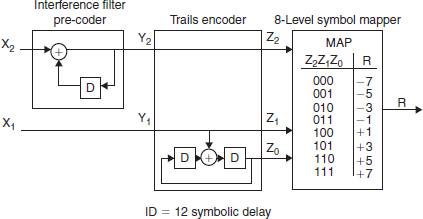
FIGURE 5.20
Main service trellis encoder, precoder, and symbol mapper (Derived from ATSC A/53)
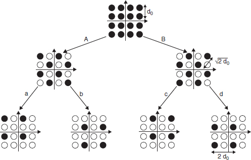
FIGURE 5.21
Modification of 16-QAM constellation by trellis coding to reduce valid data one point to one per quadrant, thereby improving transmission error resilience
Digital modulation techniques
Different modulation techniques are used over each TV delivery channel. They are vestigial sideband (VSB), QAM, and quaternary phase-shift keying (QPSK).
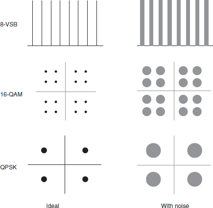
FIGURE 5.22
Digital modulation: VSB, QAM, and QPSK constellations and the effect of random noise
Figure 5.22 compares the different constellations produced by each method. On the right side of the illustration, it is clear that even if the signal is corrupted by noise, because the information is digital, it assumes discrete locations and innately offers some degree of noise immunity. An analog TV signal would start to look “snowy.”
There is an irony to the term “digital modulation.” In actuality, digital symbols of a defined bit length are mapped to voltage levels and modulate a carrier wave, exactly the same as in analog modulation. The difference is that analog modulation can be any voltage in the signal range; digital modulation is restricted to a limited number of voltage levels.
8-Vestigial sideband modulation
The ATSC DTV transmission system uses 8-level VSB or 8VSB modulation. The eight indicates that there are eight distinct voltage levels corresponding to symbols. Symbols consist of 3 bits of data.
Figure 5.23 illustrates how the eight levels modulate the carrier wave. Notice how both the top and bottom of the carrier way reflect the value of the symbol. In amplitude modulation, this will create additional signals. These sidebands expand the range of the signal about the carrier wave as shown in Figure 5.24.
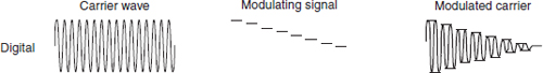
FIGURE 5.23
8-level VSB digital modulation
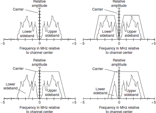
FIGURE 5.24
Vestigial sideband filtering
The use of the term “vestigial” refers to the lower sideband that is mostly filtered out before transmission. A small vestige remains, as shown in the lower right.
Quadrature amplitude modulation
QAM is a technique where quadrature carriers, waves with a phase difference of 90°, are amplitude modulated. The modulation scheme is used extensively in cable systems.
Figure 5.25 shows how the two waves are amplitude modulated and combined and then produce a constellation.
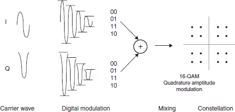
FIGURE 5.25
Digital 16-QAM modulation encodes two quadrature (a phase difference of 90 degrees) with two bit binary symbols 00, 01, 11, and 01

FIGURE 5.26
Quaternary phase-shift keying
The constellation is characteristic of the number of voltage levels that modulate each carrier. This example shows 16-QAM and has 4-bit points in each quadrant. A 64-QAM constellation would have 16-bit points in each quadrant. Today, 256-QAM modulation is commonly utilized.
Quaternary phase-shift keying
Satellite systems use QPSK. Figure 5.26 shows how 2-bit symbols are mapped to the phase of the carrier signal.
The resultant constellation, shown in Figure 5.27, has a data point in each quadrant. QPSK can also use more than four phases, which results in a higher data-carrying capability.
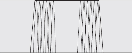
FIGURE 5.27
Coded orthogonal frequency division multiplexing divides a channel into many carrier waves, a spread spectrum technique, and modulates each carrier with a symbol
COFDM
The modulation method implemented in DVB-T systems is coded orthogonal frequency division multiplex (COFDM). A delivery channel is populated with many narrow bandwidth carriers as shown in Figure 5.27.
Each carrier contains a single-coded symbol of information. The improvement in noise immunity occurs because the symbol data is valid for a longer period of time than in other digital modulation techniques. This minimizes the potential for a bit to be totally corrupted by a noise burst, based on the concept that the noise burst will be significantly shorter than the time length that data is valid.
Multiple platform distribution
As we have been discussing, TV content distribution has expanded to include every conceivable delivery platform. Television, regardless of the compression engine, uses an MPEG-2 TS to feed the distribution technology. This standardization simplifies assembly.
Data rate must be adjusted for the delivery channel and consumption device. A DTV MPEG-2 TS is nearly 20 Mbps; this does not fit Internet distribution capacity.
MPEG-2 TS packet IP encapsulation
One approach that is used when data rates permit is to encapsulate MPEG-2 trans-port packets in an IP packet. Figure 5.28 shows how seven DTV transport packets are packed into an Ethernet frame.
Of course, the caveat is that network bandwidth must be able to provide an adequate, sustainable data rate. Over GigE, this is not really an issue for a 20 Mbps HDTV payload, but for the public Internet with data rate below 10 Mbps, this is impossible.
This technique can be used for Internet and handheld TV content delivery. It is becoming more feasible as advance compression codecs produce lower-bit rate, higher-quality content streams. Although HD resolution is in the 8 Mbps area, SD programs can be compressed to 1 Mbps and audio can be delivered via MP3.
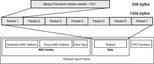
FIGURE 5.28
MPEG-2 transport packet Ethernet encapsulation
Internet bandwidth will continue to increase, while compression codecs will become even more efficient.
Network signaling
Internet broadcasting and streaming to handheld devices use real-time and group networking techniques. The relevant protocols are:
![]() RTSP: Real-Time Streaming Protocol
RTSP: Real-Time Streaming Protocol
![]() RTP: Real Time Protocol
RTP: Real Time Protocol
![]() IGMP: Internet Group Management Protocol
IGMP: Internet Group Management Protocol
Figure 5.29 presents the protocols used to deliver video over the Internet.
In contrast to DTV delivery, Internet media delivery does not use any form of FEC. In fact, even TCP retransmission control has been abandoned for UDP, in an effort to squeeze every bit of delivery bandwidth.
Content consumption
Consumer enjoyment of the original work of art, message, or signal—that is, consumption—is our raison d'être. TV content is everywhere.VOD, PPV, and recording on a DVR enable consumers to enjoy their TV experience whenever they choose. This has transformed media consumption from by appointment to on demand.
Figure 5.30 shows a typical TV scenario from just a short time in the past. Each set was an island unto itself. A DVD or VCD was necessary either to view programs at a time other than when they were broadcast or to transport content from one television to another.
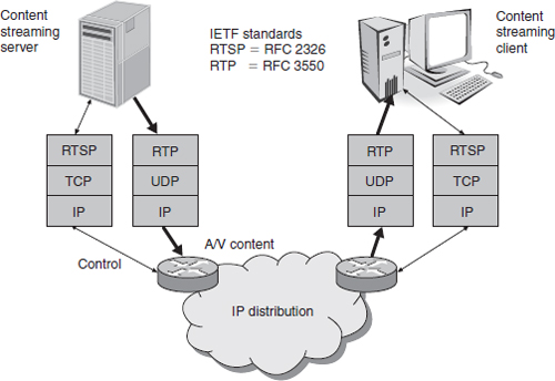
FIGURE 5.29
TV content distribution over the Internet
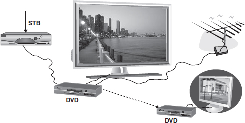
FIGURE 5.30
A multiple-room TV-viewing environment
Distribution of TV programming to multiple televisions in various rooms is rapidly being enabled. The limitations of a single set-top box and a single DVR are disappearing as service providers install the latest generation of multiroom, multirecord/playback STBs.
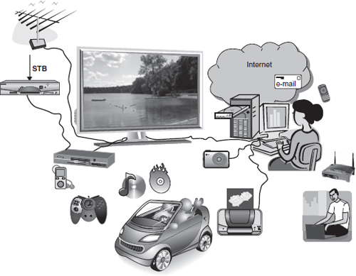
FIGURE 5.31
The interconnected media consumer
Consuming content on multiple devices
Personal home digital networks are transforming media consumption. Networked home media has accustomed the early-adopting consumer to being pampered and getting what they want, where they want it, and when they want it. Transparent transcoding of content format in the home network is being facilitated with increasing ease. And of course,“I” should be able to exercise my “fair use” rights to copy content. But creators’ rights must be protected across platforms in the home network.
Figure 5.31 shows just a sample of how the consumption environment has expanded. The long-ago predicted networked media home is at hand.
Content transfer among devices
A key issue to resolve before a truly interconnected home media network proves to be user friendly is the need to establish device interconnection methods. This includes the physical layer and the protocol stack that rides over it. In an effort to remove this bottleneck, a number of technologies are under development and vying for a position in the connected consumer's home.
Ease of installation concerns have led to development of techniques that use the existing wired infrastructure. Every house has electricity available at outlets in every room. HomePlug and other powerline-based technologies can distribute content over the existing power infrastructure.
Similarly, nearly every home has been wired for landline telephones. The Home Phoneline Network Alliance (HomePNA) uses existing twisted pair residential phone-lines for data transmission. Data rates of 200 Mbps are realistic.
With the large installed base of cable TV subscribers, use of existing coax is another option. The Multimedia over Coax Alliance (MoCA) consists of major MSOs and is a viable solution for in-residence content distribution even if it is delivered to the home over a fiber optic network.
In an ideal home networking environment, no cables would be necessary. Wi-Fi content distribution is possible depending on the required data rate. Consumer solutions are just beginning to appear on the market.
There's a lot more about consumer connectivity in Book 2.
RISING TO THE CHALLENGE
The challenge for those in the production and transmission domains is to make the creation/assembly/distribution workflow efficient for consumption on any consumer device.This takes coordinated business, creative, and technological planning.