Appendix E: Image processing
In order to process an image on a computer system, the image must be converted to digital form. PCM, which we discussed earlier, is most frequently used for audio, but it can be applied to conversion of an image from analog to digital. However, the process is more complicated than it is for audio.
The first step for an imaging device is to convert photons of light to an electrical potential. Then the image is scanned, in a method that is the same as when the image is eventually displayed. Scanning results in a series of pixels.
Here's how it works, in rudimentary terms. A pixel has characteristics that can be described in terms of its red, green, and blue components. Each of these has an intensity value, which maps to a code word. The pulse is the temporal relationship of pixels, and each pixel represents a sample. Again, modulation is a result of varying the amplitude of the sampling clock.
Installation of a circuit board with video input and output in a computer system is necessary to capture and digitize video. These “frame grabbers” were the first steps in the emergence of digital imaging; they converted frames of video to files of data.
DIGITAL PHOTOGRAPHY
Chemical-based film photography has all but disappeared. Film has superior resolution compared to digital image formats; in fact, a driving requirement of HDTV development was the image resolution approach of film. Yet even with film's high-quality imagery, convenience has won out and consumers have flocked to digital cameras and computer storage rather than negatives and video displays. Digital picture frames abound on office desks.
Ten megapixel digital cameras are the choice of many consumers. A PC is an image storage system and processing lab. Got red eyes on the people in your photo? Don't worry; the software will get rid of it for you. Today's image processing software is very sophisticated, and the latest PCs can run the programs with ease. Twenty years ago, those in digital imaging would have killed to have the kind of processing power most people now have on their desktops.
But 10 megapixels take up a lot of hard drive space. In light of the expense and scarcity of disk space, imaging research looked for ways to reduce the size of digital image files. The result is JPEG, which bears the name of the ISO working group that standardized the technique: the Joint Photographic Experts Group. The formal stan-dard was adopted in 1994 as ISO 10918-1.
The first digital cameras for the consumer market that worked with a home computer were the Apple QuickTake 100 camera (1994), the Kodak DC40 camera (early 1995), the Casio QV-11 (with LCD monitor, late 1995), and Sony's Cyber-shot Digital Still Camera (1996).
The family album has given way to the ease of electronic storage. Collection of your images on your PC is automated. Printers produce high-quality copies, and you don't even need a PC to print: just plug the photo memory card into the printer and you're all set.
Digital cameras are everywhere. If you've got one in your cell phone or PDA, then just aim, shoot, and e-mail; you'll never miss capturing and sharing magic moments.
Of course the television had to get into the act. All you have to do is select the pictures you want and let the software burn a DVD or CD that you can play back with your component DVD player. The digital camera, PC, and television are now part of the home network.
DIGITAL CINEMA
Just as motion picture technology was born from still photography, digital still images are the basis for digital cinema. Frame rates and pixel grids determine the amount of detail present and how much of that detail survives frame to frame.
Digital production, distribution, and presentation have advantages that the film indus-try cannot overlook. Many cinematographers still prefer the “film look” to video, but movie production has gone digital using a process dubbed Digital Intermediary (DI).
Compare special effects of 20 years ago with those of today. If the desired effect could actually be achieved, it took an army of artists, working film frame by frame to produce a clip, a very expensive and time-consuming process. In a DI workflow, the first step is converting the film content, frame by frame, to digital video. This is done by a datacine machine, the descendent of a telecine machine.
Once in digital form, software-based editing and image processing systems can do anything—yes, anything—with the image. Although the conversion of film-to-digital video process can be expensive and time-consuming, the time and money saved during production and the freedom from artistic limitations make the overall DI process cost-effective and creatively liberating.
Copying a film master to produce thousands of distribution copies is another expense that can be reduced with films in digital format. Movies can be transferred as digital files over commercial content distribution networks to digital theaters. By comparison, the network connection is cheaper than producing and delivering copies to hundreds or thousands of theaters.
Digital cinema is still in its infancy. But the number of locations where digital projection systems have been installed is growing rapidly around the world. A major expense, in addition to the initial installation of a digital projection system, is having sufficient disk space to store the digital “film.” We're talking about terabytes. Consider a 10-screen multiplex cinema with a movie for each screen. Don't forget the space needed for a safety, backup copy.
Presentation of digital movies, as with DTV, is perfect. Digital files don't wear out, so there aren't any film scratches or other deterioration over viewing lifetime. The 1,000th presentation is at the same quality as the first.
Besides the scale of the presentation, digital cinema has an advantage over tele-vision. One is that digital movie image resolution starts at 2K, roughly the same as 1080p24, and then increases to 4K. Details not visible in HD can be seen in 4K digital cinema.
DIGITAL SIGNAGE
Fremont Street in downtown Las Vegas has long been a kaleidoscope of visual images since the first casinos installed neon lights. But they pale in comparison to the domed display, close to a 1/4-mile long and 100-feet wide, and the “light show” that's now presented nightly. The original system, which began construction in 1994, consisted of dozens of custom computer circuit boards controlled by a custom authored software application. It was upgraded to LED technology and higher image resolution in 2004. The resulting experience is unforgettable.
Conspicuously in sports arenas and shopping malls, static billboards are being replaced with LCD displays. Coupled with computer control, sophisticated sequences of video, graphics, and text can be programmed and run with ease.
The technology is called digital signage and is an emerging outlet for all types of media. It is expected to be a large player in the future of out-of-home media.
IMAGING CHARACTERISTICS
The emergence of the PC, video games, and Internet was fueled by the development of the general-purpose microprocessor. Rather than being large electronic computer systems designed for a specific purpose, the Z80, Motorola 6800, and Intel 8080 were discrete devices that could perform a variety of mathematical, logical, data movement and storage functions.
Math coprocessors were tweaked for number crunching and supplemented the core microprocessor, and became an option for PC systems in the 1980s. An Intel 80286 would be supplemented by an 80287 math coprocessor. Next down the R&D pipeline were digital signal processors (DSPs). These were specifically designed for the heavy computational demands and data transfer speeds necessary for media applications.
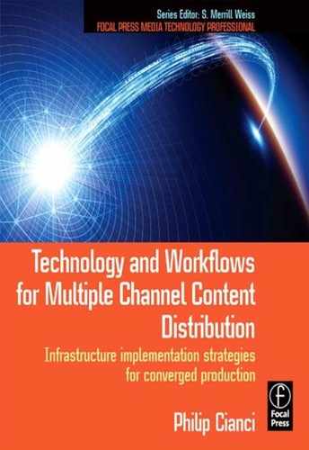
A generic image processing workflow is presented in Figure E.1. It is very simple: capture the image, store the image, process the image, store the results, and then display the image.
Storage is a key component of digital media processing systems. Only recently have the prices of RAM and disk storage reached a cost-effective level for general production use. Remember that half-million-dollar SGI Origin I talked about earlier? In 2000, 100 GB of RAID (Redundant Array of Inexpensive Disks) cost $125,000. A dual-port HD-SDI I/O card was $20,000. Not very many broadcasters could afford this, except CBS, which used the system for its first HD broadcasts.
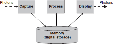
FIGURE E.1
Digital image processing pipeline
By the turn of the millennium, the convergence of the DTV and Internet revolutions was becoming feasible if not quite yet a reality. About 5 years later, handhelds attain similar capabilities. All this has been enabled because processing power, stor-age and memory read/write speeds, and internal bus bandwidth have reached the ability to support real-time audio, video, and graphics.
Digital image formats can be broken down into their constituent building blocks. These are aspect ratio, pixel grid, frame rate, scanning method, and color space. Each combination of these attributes can be considered a presentation format. Let's take a look at each.
Aspect ratio
Probably the first thing anyone noticed about HDTV was the different screen geometry. The 16 × 9 aspect ratio looked a lot larger than 4 × 3 analog TV. In a multiplatform universe there are other sizes to reckon with. Film uses ratios up to 2.25 × 1, and a 6 × 4 photo is 1.5 × 1. Aspect ratio has now become a concern for content repurposing.
Preserving the artist's visual intent can be difficult. Consider the scene in Figure E.2 presented in four different aspect ratios. We'll consider the 4 × 3 image the source; this is the way the camera operator intended the shot to be framed. Converting to 6 × 4, some of the sky is lost, but there is not much of a dramatic impact on the scene. Cropping for 16 × 9 obviously changes the image aesthetics. The subjects seem to be integrated with the falls. In the 2.25 crop the focus has clearly shifted to the subjects and the falls are more of a backdrop.
Pixel grid
The concept of breaking an image up into a pixel grid is characteristic of digital imaging. Figure E.3 shows the steps in the progression. Film is an emulsion; detail resolution depends on the fineness of the particles. Film is generally considered the highest attainable resolution.
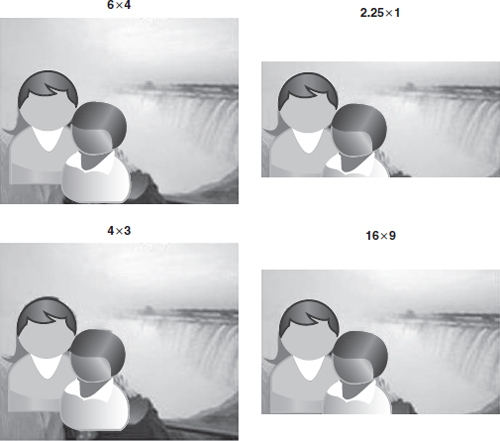
FIGURE E.2
Comparison of imaging aspect ratios
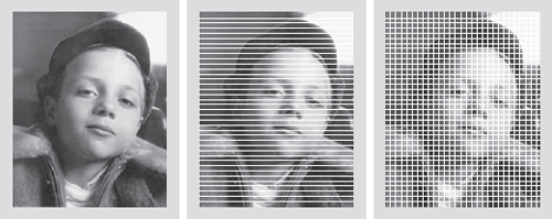
FIGURE E.3
Image capture and display techniques
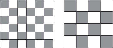
FIGURE E.4
A comparison of pixel grid resolution. The grid on the left has nine times the resolution of the one on the right
Analog TV dissected the image into distinct lines but maintained the continuous variance of luminance and chrominance on a line. In the horizontal direction, there aren't any individual pixels. CTR technology, even for DTV, still employs this mechanism.
But when an image is digitized, the lines are further broken down into individual picture elements. The result is a pixel grid.
The number of vertical and horizontal pixels determines spatial resolution. Consider an image that is 400 by 600 pixels. (Please note the numbers selected in these examples are for simplicity.) The total number of pixels is 240,000. On a 4 × 6 inch print, this equates to 100 pixels per inch.
Now consider an image with three times the vertical and horizontal resolution. 1200 by 1800 results in 2,160,000 pixels at 300 pixels per inch, three times the number in both the horizontal and vertical directions: an overall increase by nine times over the same area. Figure E.4 compares two pixel grids. Note the differences in detail capture capability of each pixel grid.
Pixel grids are naturally inclined to digital technology. With red, green, and blue values stored in memory, a simple two-variable loop can access each value and activate each element (see Listing E.1).
To process an image, data is read out in this fashion from a frame buffer, processed, and then stored. To display the image, it is moved to the display buffer, which, when fully loaded, is sent to the screen.
The number of times the display is updated in a second is called the refresh rate.
Refresh rate
Motion in motion pictures is based on the visual attribute of image persistence. The physiology and neurology of vision retains an image for a short period of time. This visual hysteresis is exploited to create the illusion of continuous motion. Research has revealed that if an image is repeated at a rate of over 24 times per second, jitter is not visible to the human eye.
A small variety of refresh rates are used across the globe. In the United Kingdom and Europe, 25 and 50 Hz are used. The selection has to do with meeting the perceptual hysteresis minimum because electrical AC power is at 50 Hz. By using identical frequencies, techniques can ensure that artifacts produced by differences in refresh and power rates aren't noticeable.
The United States uses 60 Hz AC power, so the original NSTC I black-and-white TV system was at a 60 Hz display refresh rate. However, the development of color television necessitated the need to slightly alter the refresh rate to 29.97 to avoid audio carrier issues. The ratio between the two is 1000/1001.
But there are fundamental issues when it comes to TV and PC displays. Television in the United States is based on a 29.97 Hz frame refresh rate, a lingering vestige of the analog NTSC II system. PCs operate at 60 Hz and other “exotic” rates.
The other difference is the scanning method.
Scanning method
As just discussed, television imaging dissects an image into a series of horizontal lines. The obvious way to do this is to start at the top of the image, scan the line, jump down the distance of one line and move back to the beginning, then scan the next line, and so on until the entire frame has been processed. This sequential scanning of line 1, then line 2, is called progressive scanning. Progressive scanning is exclusively used in computer displays. Refresh rates are in terms of frames per second.
Early TV systems were constrained by the bandwidth of the terrestrial delivery channel. In the United States, this was, and still is, 6 MHz; in PAL systems deployed in the United Kingdom and Europe, channel bandwidth is 8 MHz. This required some form of data reduction in order to fit the TV signal into the channel space.
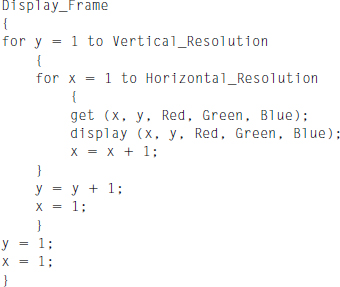
LISTING E.1
Pseudo C code pixel grid frame display algorithm
A technique where a frame of video lines is divided into two fields, one of odd lines and the other of even, was devised. The technique, known as interlacing, is used today in DTV systems. Any format with an “I” in it denotes interlaced scanning.
DTV offers the choice between delivering content using either progressive or interlaced scanning. Conversion between the two is not trivial and is discussed in Chapter 9.
Color space and gamut
Accurate rendition of color is imperative for photography. The driving motive of photography is realism. Regardless of whether chemical or electronic image reproduction technology is used, color fidelity is dependent on the spectral properties of each of the primary colors. Images are “colorized” by the use of three-color systems. Printing to paper is a color subtractive process and uses cyan, yellow, and magenta, along with black. Video displays use red, green, and blue primaries in an additive process.
All color primaries are not equivalent. They are dependent on the chemical properties of the material used to reflect or produce light. This causes differences between primary colors used in negatives, paper, imager, and displays. As shown in Figure E.5, the location of red, green, and blue primaries on the CIE color chart varies. If the R, G, and B values are connected to form a triangle, it becomes obvious that different sets of primaries produce different ranges of color.
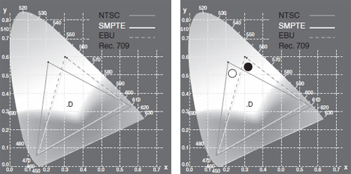
FIGURE E.5
Color primaries and gamut mapped on the CIE color chart
The area inside the triangle is called the color gamut. All colors in the natural world are beyond any set of primaries that can be reproduced on a display system. It is obvious that some sets cannot produce some colors that other sets can.
But there is a more subtle effect of color primary variation. Consider adding equal amounts of R, G, and B to make white. The point where the primaries intersect to form white is in a different place for each set of primaries. Amazingly all whites are not the same white. The whiteness of a white is expressed as color temperature: 6500 K for daylight. Lower values tend to be more orange; higher, bluer.
While computer systems work with red, green, and blue primaries, TV systems exploit human visual system characteristics to reduce the amount of information so that the highest quality image can fit in the transmission channel.
Red, green, and blue image information is converted into luminance and chrominance signals. Figure E.6 shows the waveforms for the color bar test signal.
As the equations show, different amounts of red, green, and blue are combined to produce a luminance signal “Y” and two color difference signals “B-Y” and “R-Y.” The conversion equations are based on the sensitivity of the eye to red, green, and blue.
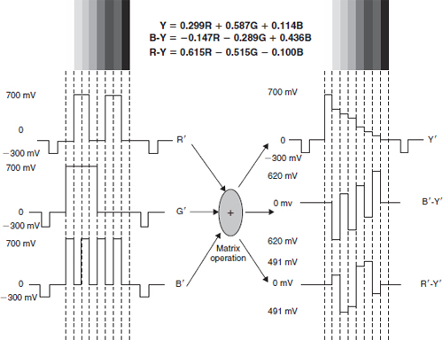
FIGURE E.6
Color space format conversion
Bit depth and data volume
Each pixel is represented by a red, green, and blue value. If each of these is a byte (8 bits), the total number of bytes to store each of the image examples is 5,760,000 for the 400 × 600 image and 51,840,000 for the 1200 × 1800 image. The resolution of each color is 256 distinct values, and the total number of colors that can be produced is 256 × 256 × 256 or 16,777,216.
Professional production will use 10-, 12-, or even 24-bit color depth; 8 bits are sufficient for consumer applications. The longer words are necessary to avoid artifacts created by accumulated round-off errors during image processing.
Color sampling
Another technique that exploits human visual characteristics is the fact that the eye is less sensitive to color detail than it is to luminance detail. Hence color information can be reduced.
When red, green, and blue are converted to Y, there is a one-to-one correlation; a triplet of RGB produces one Y pixel. But with the color difference signals, the conversion is not one-to-one. Depending on the color sampling technique, one pair of chrominance pixels may be produced for every other RGB triplet on a line. This cuts the amount of chrominance data into half. A further reduction can be achieved by only producing chrominance data for every other line, resulting in one pair of color data points for four luminance pixels.
COMPRESSION IN IMAGING
Researchers realized that development of techniques to reduce the amount of data in a digital image would reduce the amount of storage and cost necessary to build digital image libraries. Business people understood that this would help bring about mass commercialization and consumer uptake of digital photography.
Another driver of compression technology development was the need to compress images for digital high-definition television. Audio compression was developed to introduce surround sound to movies. Internet delivery also played a role.
TIFF was an early compression format that is still in use today in image archives. TIFF is a lossless image compression technique. Lossless image compression uses data reduction techniques that will exactly reproduce the original image data; byte for byte, the data is identical to the original.
Lossy, or perceptual, compression removes image detail that is imperceptible to the human eye. The reverse process, decompression or decoding, results in a less than perfect reconstruction of the original image; byte for byte, the data may differ. The trick is that people won't perceive the visual information removed as missing in the reconstructed image. Similar psychoacoustic attributes are used in audio compression.

FIGURE E.7
JPEG processing block diagram
JPEG
The Joint Photographic Experts Group, an imaging industry consortium, was formed in 1986 to consolidate investigations into image compression and to develop a consensus standard. The resultant technique has become an acronym known to all: JPEG.
JPEG is a lossy image compression format. Although a JPEG file can be encoded in various ways, most commonly it is done with JFIF encoding. The encoding process consists of several steps as shown in Figure E.7.
![]() The color space of the image is converted from RGB to YCbCr (Cb and Cr are forms of B-Y and R-Y). This step is optional.
The color space of the image is converted from RGB to YCbCr (Cb and Cr are forms of B-Y and R-Y). This step is optional.
![]() Chroma data is reduced, usually by a factor of 2.
Chroma data is reduced, usually by a factor of 2.
![]() The image is split into blocks of 8 × 8 pixels; each block of Y, Cb, and Cr data is converted from the spatial to the frequency domain via a discrete cosine transform (DCT).
The image is split into blocks of 8 × 8 pixels; each block of Y, Cb, and Cr data is converted from the spatial to the frequency domain via a discrete cosine transform (DCT).
![]() The amplitudes of the frequency components are quantized. Resolution is determined by how each of the frequency components is quantized. The more the bits used for high-frequency information, the higher the image resolution.
The amplitudes of the frequency components are quantized. Resolution is determined by how each of the frequency components is quantized. The more the bits used for high-frequency information, the higher the image resolution.
![]() The resulting data volume is reduced with a lossless Huffman encoding algorithm.
The resulting data volume is reduced with a lossless Huffman encoding algorithm.
The decoding process reverses these steps.
MPEG-1 and DVDs
CDs had been such a business success that it was only natural to envision a way to store movies on a similar optical medium. The vision of potential profits by heavy hitters in the consumer electronics industry launched a competition reminiscent of the VHS/Beta battle.
In the early 1990s, two high-density optical storage standards were being developed: MultiMedia Compact Disc (MMCD), by Philips and Sony, and the Super Density Disc (SD), supported by Toshiba, Time-Warner, Matsushita Electric, Hitachi, Mitsubishi Electric, Pioneer, Thomson, and JVC. Legend has it that IBM President Lou Gerstner led an effort to unite the competitors behind a single standard.
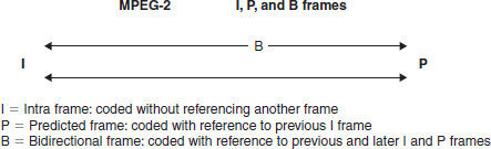
FIGURE E.8
The relationship among I, P, and B frames
Eventually Philips and Sony abandoned their MMCD format and agreed upon Toshiba's SD format with two modifications related to the servo tracking technology. This enabled the inclusion of Philips and Sony technology in the standard and the derivation of revenue from intellectual property IP licensing.
Video had to be digitized; optical recording is a digital technique, storing ones and zeros in the glass substrate. To resolve the obstacle, the JPEG tool kit added features that supported motion. The result was MPEG-1 (the M is for motion). Video storage on DVDs initially used MPEG-1 and has moved on to MPEG-2 compression.
The first DVD players and discs became available in 1996 in Japan, March 1997 in the United States, 1998 in Europe, and 1999 in Australia. Video resolution was limited to 352 × 240 at 30 fps. This produces video quality slightly below the quality of conventional VCR videos.
Perhaps the most innovative feature of MPEG-1 was the technique of encoding some images as only the difference between one image and a previous image. In practice, three frames types are used: I, P, and B.
![]() I—Intraframe: an anchor frame that can be decoded without reference to another frame; in essence, a JPEG image.
I—Intraframe: an anchor frame that can be decoded without reference to another frame; in essence, a JPEG image.
![]() P—Predicted: a frame that encodes the difference in an image with respect to a previous I frame.
P—Predicted: a frame that encodes the difference in an image with respect to a previous I frame.
![]() B—Bidirectional: a frame that encodes the difference between this frame and earlier of later I or P frames.
B—Bidirectional: a frame that encodes the difference between this frame and earlier of later I or P frames.
Figure E.8 shows the relationship between the types of compressed frames.
Further developments to the original MPEG-1 standard resulted in MPEG-2 and MPEG-4 standards. Ongoing work by MPEG working groups is the development of MPEG-7 and MPEG-21, both of which address content management.