Embedded control fundamentals
Abstract
This chapter shows the novice the basic information to get started on wiring up their processor. Images of a dual inline package (DIP) integrated circuit (IC) show how to read the pinout. Basic and specialized inputs and outputs are discussed. Timer modules and registers are separately addressed with three options: hardware alone, hardware and software, and software alone. Development boards are suggested.
Keywords
Embedded; Pinout; Wiring; Diagrams; Connections; Hardware; Software; Power; Ground; Fundamentals
Embedded Control
Embedded control refers to electronic devices that have user programmable space for software and connections to external circuitry through hardware. Embedded control devices have a very specific set of tasks, or states, that they are designed specifically for accomplishing. The user only interacts with specific inputs, like switches, and receives specific responses in output, such as light emitting diodes (LEDs). Generally, they are not used with a keyboard or mouse, and they typically do not provide any provision for user programmability.
Electrical Wiring Diagrams
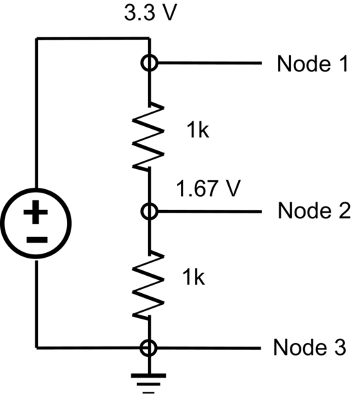
Nodes are points of electrical value where the electrical characteristics are identical across the connections. Herein, the impedance and capacitance of the wire, and connections to that wire, are similar enough across it as to be considered of negligible difference.
Looking at Fig. 6.1, there are three nodes to consider; Node 1 at 3.3 V, Node 2 between resistors, and Node 3 at ground. Node 2 is calculated as a ratio of the two resistors; R1 and R2. Ohm’s law, V = IR; where V is voltage in kilovolts, I is current in amperes, and R is resistance in kilohms. Rewritten as R = V/I. If Node 2 is of interest to us, we can use the resistor ratio to calculate the voltage at Node 2. Vnode2 = (R2/(R1 + R2)) * 3.3 V = (1k/2k) * 3.3 V = 1.67 V (Fig. 6.2).

Breadboards
Breadboards are temporary work boards for electronic circuits. The general shape of a breadboard is shown in Fig. 6.3. Compatible with most breadboards, 24-gauge wire is used to connect circuits; solid wire, not stranded. Sometimes, kits may be available with various colors of fixed lengths to specifically fit breadboards. These are a nice convenience.
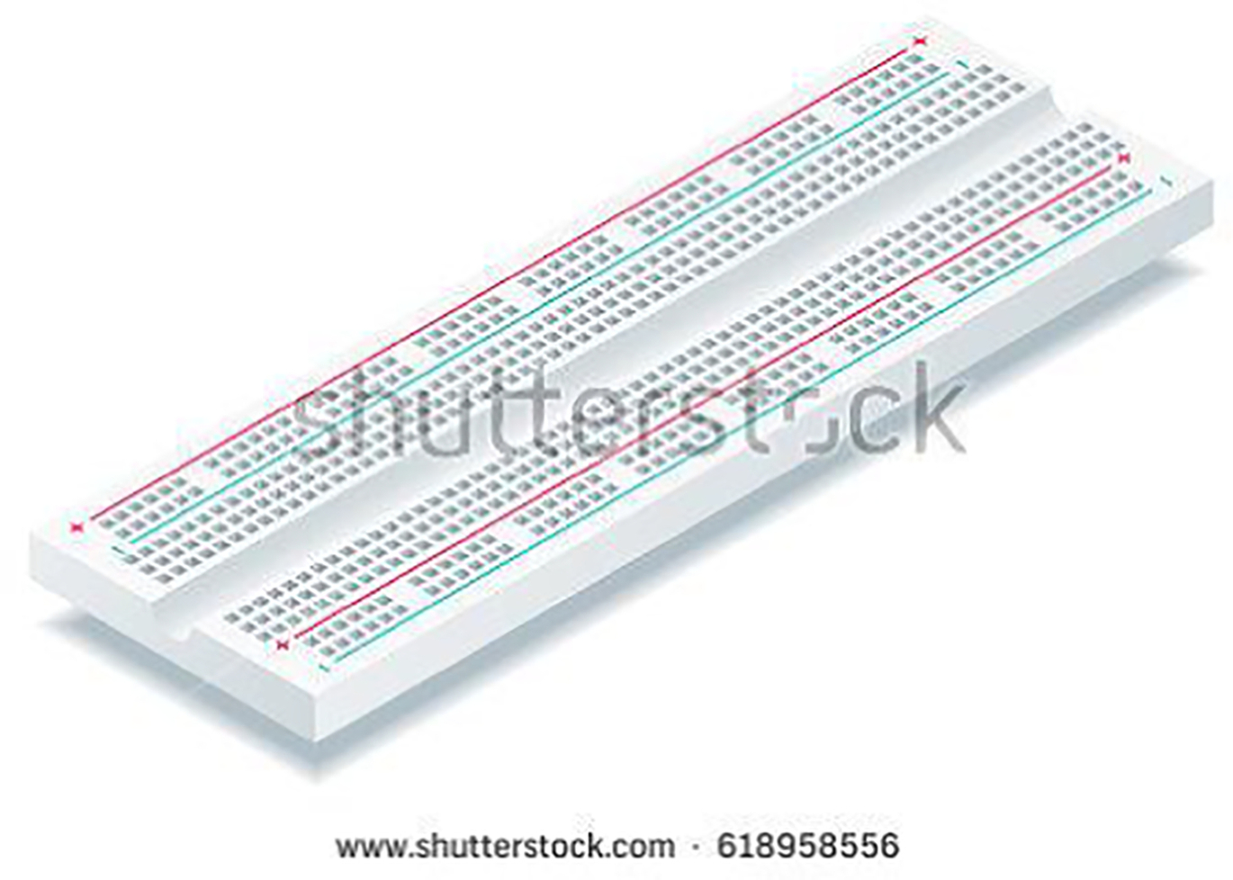
A bare board, Fig. 6.3, already has some connections. The horizontal rows are connected throughout the row and may make a complete row with the addition of a simple jumper at the center point. These rows are noted with red and blue or black markings (Fig. 6.4).
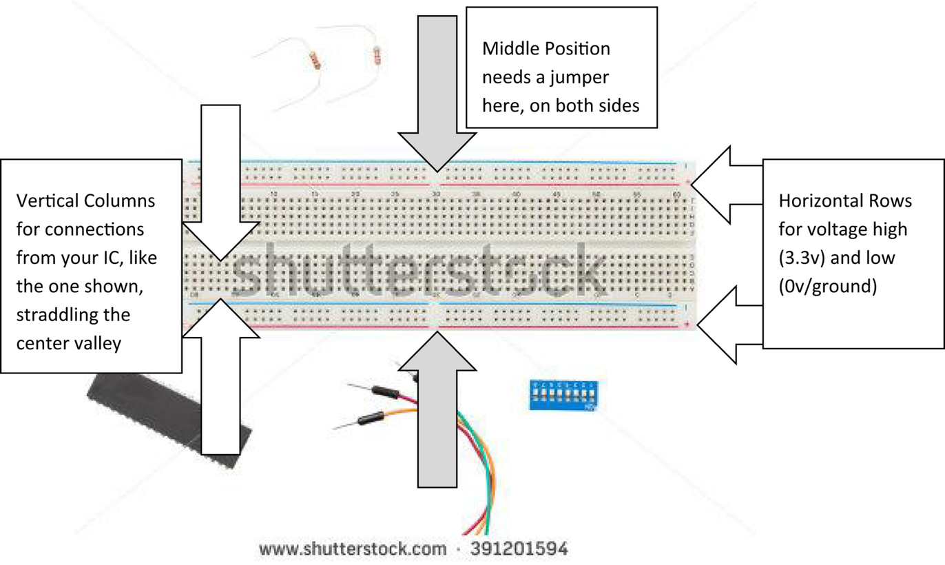
Similarly, the vertical columns are connected vertically down half the width of the board. A jumper may be inserted at the middle location to connect the full width of the breadboard. The horizontal rows are typically used for power and ground, and, with the middle NOT connected, one can apply more than one power level, such as 12 V, 3.3 V, and ground. Fig. 6.4 shows the orientation of the board for our purposes. As noted in Fig. 6.4, vertical columns are for connections to each leg of your integrated circuit (IC). Like the three integrated circuits shown in Fig. 6.5, your IC should straddle the center valley.
Basic Input and Output (I/O)
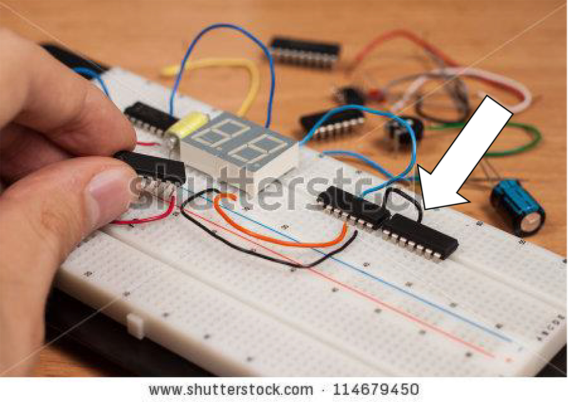
Some very basic I/O, commonly referred to as “electronic glue,” is used to setup a PIC® controller. A PIC® 10F comes in an 8-pin Dual Inline Package (DIP), although only 6 of the 8 pins are active. This package style is ideal for use with a breadboard which accommodates the DIP package to straddle the center. The three DIP packages are already placed into this double width breadboard. Note that these packages arrive with their legs splayed at an angle of about 60 degrees. Simply lay the package on its side and rock the DIP to bend the legs to a clean 90 degrees.
There is a slight dimple on the top of the device, where pin 1 is identified. Pin numbering then continues around the device; see Fig. 6.6. This pin numbering pattern is similar to all DIP packages. Note the difference between PIC10F204/206 and 10F200/202 is a comparator on the former 204/206 device; CIN + on pin 5, CIN– on pin 4, and COUT on pin 3.
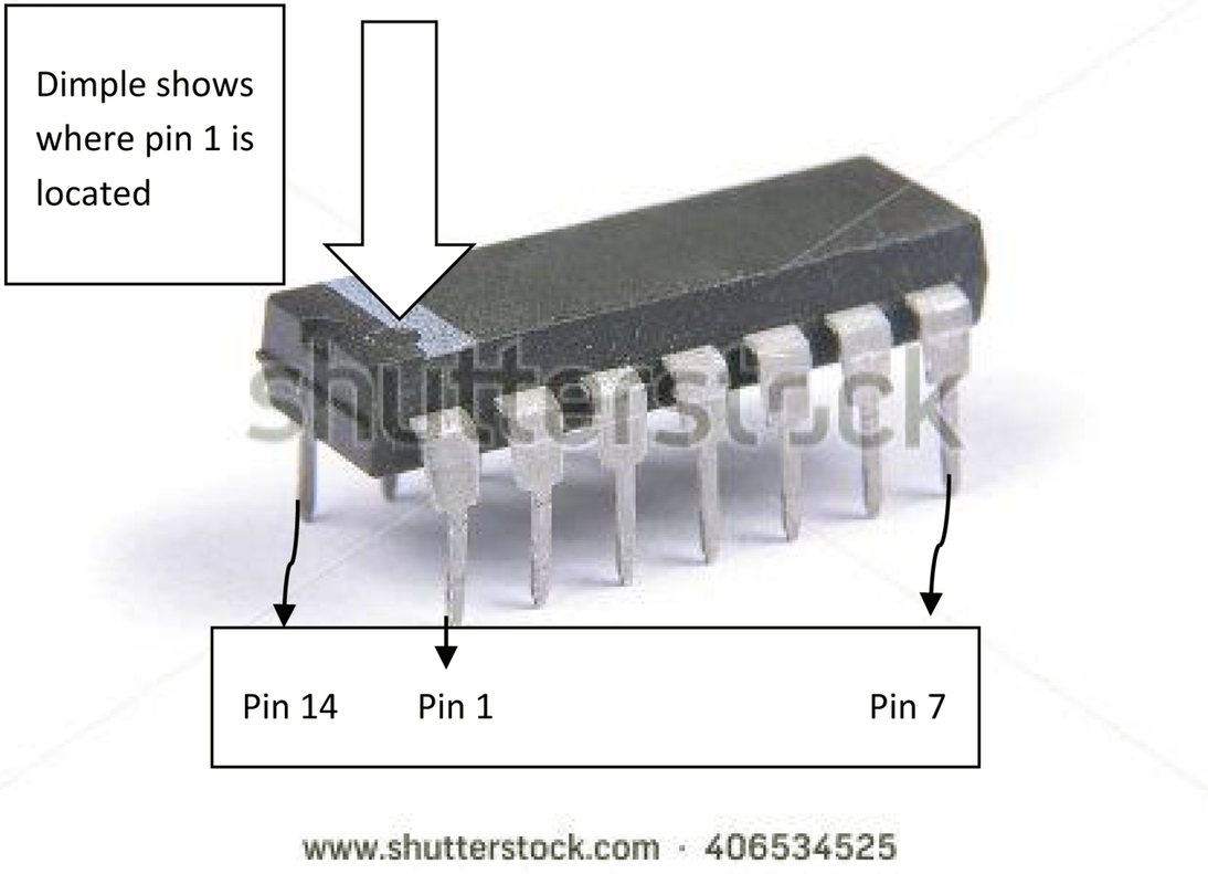
The data sheet shows the pinouts on page 2. The numbering conventions are shown in Fig. 6.6. The pinouts start on the lower left side of the 14-pin Dual Inline Package (DIP) pinout. Pins are numbered 1–7, from left to right, with pins 8 through 14 starting on the top side, from right to left, as shown in Fig. 6.6.
On the PIC10F200/202, four general-purpose input/output (GPIO) pins are shown as GP0 to GP3. Basic Inputs and Outputs (I/O) are I/O that are routinely found and available on all microprocessors. Inputs are typically 5- or 3.3-V inputs that read 0.0 V, or “ground,” when inactive and 5 V, or “high,” when active.
Other I/O may include TRIS, or Tristate, inputs. These are similar to standard I/O, except there is a third state “high impedance,” where the pin is pulled high with external high impedance circuitry, thereby offering a third state. Outputs are low, or “ground,” and “high,” 5 V. This is using internal microprocessor circuitry.
Another common means of executing other states is by pulsewidth modulation, or PWM. This output is made by alternating quickly between high and ground, and leaving high up for a known percentage of time. For example, if one were to pulse a high for three periods and then pulse a ground for one period, this would be read as 3/4 of high, or 5 V multiplied by 3/4, or 15/4, or 3.75 V. PWM is a good means to measure, or create, analog signals which use the entire range of 0–5 V.
If more basic I/O is required than is available on the PIC® controller, one can use a multiplexer provided that the I/O does not switch or change faster than the multiplexer. For every one multiplexer, there can be four or more multiplexed I/O.
Specialized Input/Output
Specialized Input and Output (I/O) encompasses a wide range of unique features offered on PIC® microcontrollers. Specialized I/O often include I/O that support unique features that are supplied internal to the microprocessor at a lower cost than if it were to be implemented external to the microcontroller. Some of these features are implemented “on top” of other features, while all taking place on the same pin.
To take full advantage of these more unique features, carefully read through the PIC® controller’s data sheet. These micros are well documented in their data sheets. Many of these specialized I/O are interfaced for additional sensor inputs, such as an onboard temperature signal or the onboard crystal for timing signals. These are typically options that are available at a slightly higher cost. This is one way to keep your options open to upgrades on the same pinout. This will position your code well as the features may be needed, after time, for a modest additional cost and would not necessarily require changing the circuit board and external hardware.
Timer Modules and Registers
There are three main ways to achieve a time delay of known duration. These are hardware alone, mixed hardware and software, and software alone. These different methods all yield different levels of accuracy. This requires knowledge of how long each cycle of the processor takes to complete individual instructions. PIC® controllers, 8-bit processors, contain crystals that create a known oscillation frequency. Some older processors require hardware connection to either an external crystal or a resistor capacitor (RC) network to create the pulse. Think of the timers as heartbeats for the processors. Every circuit will have a known pulse frequency although it may not be the same as another unit. RCs are the least accurate and least consistent of the choices. Typically, you can measure your processor’s own “heartbeat” and, with a known pulse rate, you can compensate for inaccuracies. Note that compensation must be calculated each time the processor operates as variables like temperature will dramatically affect the pulse rate. Let’s take a look at the three options to use to achieve time “intervals.”
Hardware Alone
One-shots and monostable multivibrators can produce time delays in hardware. These are among the least accurate methods but may be preferred if you do not want to have the processor tied up with “doing nothing” but counting.
Hardware and Software
A 555 CMOS timer can also be used to achieve a hardware pulse but with more consistency and accuracy. The 555 can be configured with microcontroller software to create a pulse of known frequency and pulse width. This configuration is more reliable than the hardware only process.
Software Alone
Software alone can be the best option, especially with PIC® controllers with an internal crystal. This is achieved first with a measurement of frequency and then a series of two or more nested loops to “waste time.”
Development Boards
There are a variety of development and evaluation boards available through Microchip. Reading through each processor’s data sheet to find the ideal IC and development or evaluation board. Follows are some of the available boards.
- Automotive Networking Development Board
ADM00716 $110.00
CAN & LIN network related
- Curiosity Development Board
DM164137 $20.00
- Curiosity HPC Development Board
DM164136 $32.00
Versatile for 8-bit 6-pin to 8-bit 100pin
- Explorer 8 Development Kit
DM160228 $75.00www.microchip.com/Explorer8
Includes options for external sensors, off-board communication and human interface
- PICDEM Lab II Development Platform
DM163046 $100.00
Development and teaching platform with a large prototyping breadboard to easily experiment with different values and configuration
Word Search: Embedded Control


Puzzle: Flustered
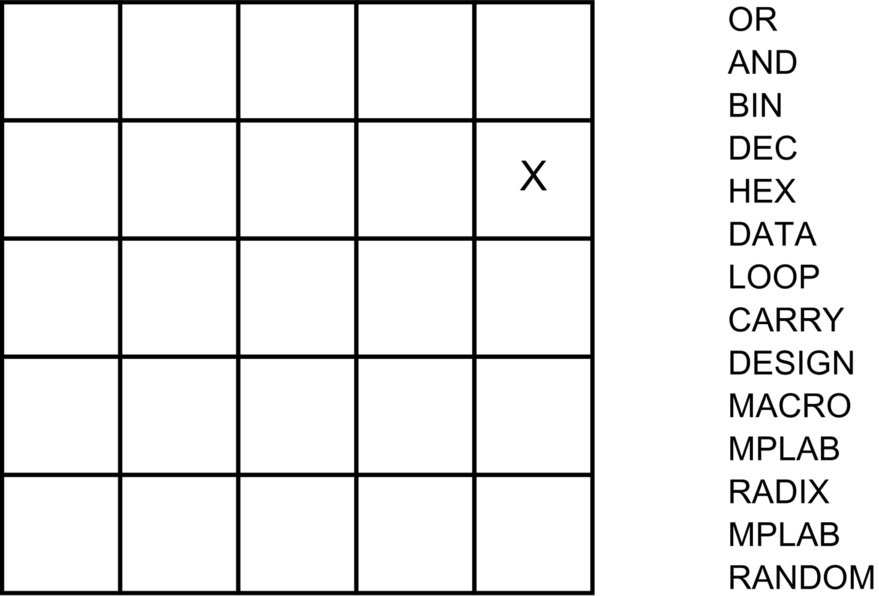
To solve the puzzle, place each of the words into the puzzle square. Letters may be shared horizontally and vertically, but not diagonally. Words are grouped by number of letters. You are given one letter's location, shown as X. To start, find a five letter word containing X, place it on the grid, and continue with words that may share letters with your first word.
How to solve Flustered
In the familiar word game Fluster, players are given 16 letters (some of which may be duplicates) arranged in a four-by-four grid. Players try to form words by moving from letter to touching letter – horizontally, vertically, or diagonally. All letters of a given word must be found in different squares. Things are turned around a bit here. In the following puzzle, a list of words from a game of Fluster is provided, and you are to determine the correct location for each letter. One letter is given to get you started.
Further Reading
PIC10F200/202/204/206 Data sheet, see Appendix E.