Logic and numbering systems
Abstract
This chapter introduces the concept of Boolean algebra and the different logical operators that are used to describe logical relations. Then it describes the different numbering systems that make up polynomial systems, namely binary, octal, hexadecimal, and decimal. This is followed by a discussion on multibyte integers, the computing methods used to represent signed and unsigned integers, and floating point. The use of the Binary Coded Decimal as an alternative means of representing decimal numbers is then presented. The chapter concludes with discussions on single- and multibyte characters, namely ASCII and Unicode, respectively.
Keywords
Boolean algebra; Logical operators; Truth tables; Binary system; Hexadecimal system; Binary Coded Decimal (BCD); ASCII; Unicode
Boolean Algebra
Boolean algebra defines a set of operations on the values true and false. True is represented as a binary value of 1. False is represented as a binary value of 0. Boolean algebra was invented by George Boole, a mathematician who designed the first computer named the Analytical Engine. It is through Boolean algebra that we physically construct hardware gates that take in inputs and generate outputs. All of these may also be constructed out of software using the logical operators.
Logical Operators
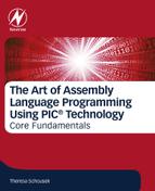
Logical Operators are assembly language commands that act on two input values and give one output value. Let’s take a look at a generic black box with the input values of A and B and the output value of F. To understand how the Logical Operators work, we engage the use of truth tables. Truth tables show, in tabular form, the inputs on the left side columns, A and B, and the output, F, on the right side column of the table (Fig. 9.1).
There are three basic functions: AND, OR (IOR), XOR. We will take a look at the AND function, for ANDWF and ANDLW; the inclusive OR function, for IORWF and IORLW; and the XOR exclusive OR function for XORWF and XORLW (see Fig. 9.2).

AND/NAND gates
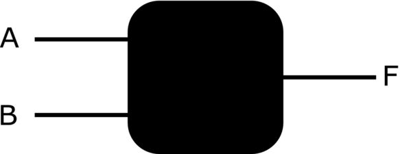
The AND gate is represented by a D shaped object. The AND gate requires that both A and B must be true (1) before the output F can be true (1). All other input combinations result in a false (0) output F (Fig. 9.3).
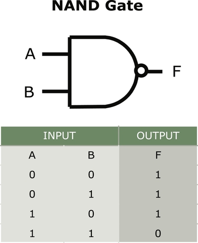
The NAND, or not AND, gate, is represented by an AND gate with a bubble on the output indicating the NOT of the output. All input combinations result in a true (1) except for the one state where both A and B are true; this state is a false (0) (see Fig. 9.4). The NAND is a very special function in that multiples of it can be used to create any of the other gates. We will look at this special relationship at the end of this chapter.

The AND Microchip assembly language logical operators are ANDWF and ANDLW (see Fig. 9.5). The logical operators are bit wise functions. The first operator, ANDWF, ands the working register, W, and the value contained in f. The destination, d, will be 0 if the solution is placed in the W register. The destination, d, will be 1 if the solution is placed in the memory location f. The second operator, ANDLW, ands the literal k with the working register W. The solution is placed in the W register.

IOR/NOR gates
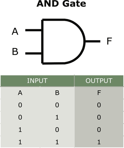
The OR gate is represented by a gate with a concave side where the inputs are located (Figs. 9.6 and 9.7). The basic OR gate may also be called the IOR gate, for inclusive OR. This means that the output will be true if both A and B are true; also, inclusive of the states where only one input is true.

As with the NAND function, NOR negates the output values for the gate. This negation is indicated by the bubble on the output of the gate. If any of the inputs are true, the output will be false. The output will be true when both inputs are false.
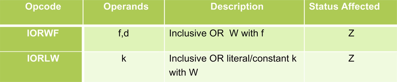
The inclusive OR, IOR, Microchip assembly language logical operators are IORWF and IORLW (see Fig. 9.8). The logical operators are bit wise functions. The first operator, IORWF, ors the working register, W, and the value contained in f. The destination, d, will be 0 if the solution is to be placed in the W register. The destination, d, will be 1 if the solution is to be placed in the memory location f. The second operator, IORLW, inclusive ors the literal k with the working register, W. The solution is placed in the W register.
XOR/XNOR gates
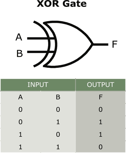
The exclusive or, XOR, is illustrated similar to the OR, or IOR, gate with a concave input side (Figs. 9.9 and 9.10). The exclusive part of XOR is illustrated with a double concave shape on the input side. The XOR gate gives a true, 1, output if one or the other of the inputs are true, 1. When both inputs, A and B, are true, the XOR gate yields a false (0).
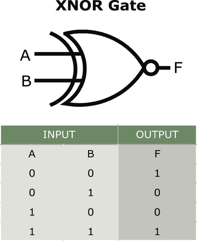
The XNOR yields a NOT of the XOR gate and truth table. When both inputs are false, 0, or when both inputs are true, 1, then the XNOR is true (1). When one of the inputs is true and the other input is false, the XNOR yields a false (0).
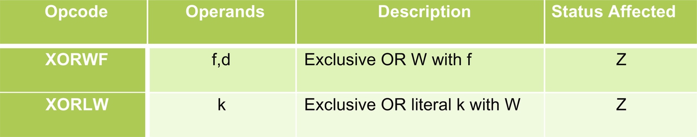
The Exclusive OR, XOR, Microchip assembly language logical operators are XORWF and XORLW (Fig. 9.11). The logical operators are bit wise functions. The first operator, XORWF, exclusive ors the working register, W, and the value contained in f. The destination, d, will be 0 if the solution is to be placed in the W register. The destination, d, will be 1 if the solution is to be placed in the memory location f. The second operator, XORLW, exclusive ors the literal k with the working register W. The solution is placed in the W register.
Gray code
Note that the truth tables, shown here, are set in an order that places the inputs in a binary order: 00 (for zero), 01 (for one), 10 (for two), and 11 (for three).
There is a better alternative known as Gray code. This sequence provides a specific order that permits only one bit to change at a time: 00 (for zero), 01 (for one), 11 (for three), and then 10 (for two). Interestingly, this technique has advantages in making more robust code. If implemented in hardware, this approach has other distinct advantages in preventing spurious output from electromechanical switches and in minimizing the effect of error in conversion of analog signals to digital. This technique is referred to as reflective binary code (RBC) or, simply, Gray code, after Frank Gray who discovered and patented this technique.
NAND, the universal operation
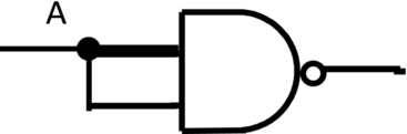
The NAND is a very special function; multiples of it can be used to create any of the other gates. We can implement various functions by using one or more NAND operators.
If we tie both inputs together, the output will be a simple NOT function.
Polynomial Systems
Decimal System
The decimal system is an example of a polynomial number system. The reason for the name is that the value of any numeral d is given by a polynomial. For example, the value of 2437 is given by the expression:
Or more simply
In the example, the polynomial in 10 is represented, whose coefficients are the digits 2437. In general, any integer can be used as the base or radix. Some important bases, used in assembly language programming, are as follows:
- • Base 2—binary number system;
- • Base 8—octal number system;
- • Base 10—decimal number system;
- • Base 16—hexadecimal number system.
The context usually makes it clear which base is being used, the standard default being 10. If working with multiple bases, or radices, the base is subscripted to the right of the value, as 243710, or indicated, as with PIC®, by the alphabetic character d: 2437d, for decimal number system.
Binary, Octal, Hexadecimal, Decimal
This chapter begins with the familiar standard numbering system of decimal. There are observations one can make on the decimal numbering system. These observations allow us to then make parallel comparisons with other mathematical systems. In this context, one can, by comparison, introduce additional systems of binary, octal, and hexadecimal. Unless otherwise noted, numbers presented in this textbook shall by default be decimal numbers.
Let’s take a look at decimal numbers. Here presented is a random 8-digit number: 53,756,598. In the decimal numbering system, one works with base 10 numbers, with numerals 0, 1, 2, 3, 4, 5, 6, 7, 8, 9. So, herein, we use this random number as a base 10 number example: 53,756,598.
| 10,000,000 | 1,000,000 | 100,000 | 10,000 | 1000 | 100 | 10 | 1 |
|---|---|---|---|---|---|---|---|
| 10 × 10 × 10 × 10 × 10 × 10 × 10 | 10 × 10 × 10 × 10 × 10 × 10 | 10 × 10 × 10 × 10 × 10 | 10 × 10 × 10 × 10 | 10 × 10 × 10 | 10 × 10 | 10 | 1 |
| 107 | 106 | 105 | 104 | 103 | 102 | 101 | 100 |
| 5 | 3 | 7 | 5 | 6 | 5 | 9 | 8 |

Note that, in decimal, base 10, the right-most first digit is the ones, as it is base 10 to the zeroth power. The second digit is base 10, 10 to the first power, or 10. The third digit is the hundreds digit, 10 to the second power, or 100. The fourth digit is 10 to the third power, or 1000. The fifth digit is 10 to the fourth power, or 10,000. And so on, until the eighth digit as 10 to the seventh power.
Binary System
Binary is the name of the numbering system that is base 2. This system, therefore, has numerals 0 and 1. That means that numerals 2, 3, 4, 5, 6, 7, 8, and 9 do not exist in this numbering system. Row 1 is the decimal (base 10) equivalent value.
As an example, use the decimal example value: 214. (This is a totally arbitrary value.) Look at the highest decimal value represented here: 128. Divide the value that we wish to represent, 214, by the value 128: 1.671875. Truncate (or “chop off”) the decimal section 0.671875. The 1 indicates that 1 × 128 is the highest value that can be placed in the 27 position.
| 128 | 64 | 32 | 16 | 8 | 4 | 2 | 1 |
|---|---|---|---|---|---|---|---|
| 2 × 2 × 2 × 2 × 2 × 2 × 2 | 2 × 2 × 2 × 2 × 2 × 2 | 2 × 2 × 2 × 2 × 2 | 2 × 2 × 2 × 2 | 2 × 2 × 2 | 2 × 2 | 2 | 1 |
| 27 | 26 | 25 | 24 | 23 | 22 | 21 | 20 |
| 1 |

Now we subtract (1 × 128) from the original value, 214, to reveal what can be represented by the rest of the value. So subtracting 128 from 214, this leaves 86 to be represented by the rest of the binary number.
To find the 26 value, divide 86 by (26 or) 64: 1.34375. Truncate the decimal value to 1. The remainder is 86 − (1 × 64): 22.
| 128 | 64 | 32 | 16 | 8 | 4 | 2 | 1 |
|---|---|---|---|---|---|---|---|
| 2 × 2 × 2 × 2 × 2 × 2 × 2 | 2 × 2 × 2 × 2 × 2 × 2 | 2 × 2 × 2 × 2 × 2 | 2 × 2 × 2 × 2 | 2 × 2 × 2 | 2 × 2 | 2 | 1 |
| 27 | 26 | 25 | 24 | 23 | 22 | 21 | 20 |
| 1 | 1 |

Continue to calculate the next value. How many 32s are in 22? Zero. Place the 0 in the 32 column.
| 128 | 64 | 32 | 16 | 8 | 4 | 2 | 1 |
|---|---|---|---|---|---|---|---|
| 2 × 2 × 2 × 2 × 2 × 2 × 2 | 2 × 2 × 2 × 2 × 2 × 2 | 2 × 2 × 2 × 2 × 2 | 2 × 2 × 2 × 2 | 2 × 2 × 2 | 2 × 2 | 2 | 1 |
| 27 | 26 | 25 | 24 | 23 | 22 | 21 | 20 |
| 1 | 1 | 0 |

Continuing with the next value, 16. How many 16s are there in 22? One. Place a 1 in the 16 column. Subtracting 16 from 22 gives the remainder of 6.
| 128 | 64 | 32 | 16 | 8 | 4 | 2 | 1 |
|---|---|---|---|---|---|---|---|
| 2 × 2 × 2 × 2 × 2 × 2 × 2 | 2 × 2 × 2 × 2 × 2 × 2 | 2 × 2 × 2 × 2 × 2 | 2 × 2 × 2 × 2 | 2 × 2 × 2 | 2 × 2 | 2 | 1 |
| 27 | 26 | 25 | 24 | 23 | 22 | 21 | 20 |
| 1 | 1 | 0 | 1 |

How many 8s are there in 6? Zero. Place a 0 in column 8. Since we are to subtract (0 * 8), or 0, the value we seek is still 6.
| 128 | 64 | 32 | 16 | 8 | 4 | 2 | 1 |
|---|---|---|---|---|---|---|---|
| 2 × 2 × 2 × 2 × 2 × 2 × 2 | 2 × 2 × 2 × 2 × 2 × 2 | 2 × 2 × 2 × 2 × 2 | 2 × 2 × 2 × 2 | 2 × 2 × 2 | 2 × 2 | 2 | 1 |
| 27 | 26 | 25 | 24 | 23 | 22 | 21 | 20 |
| 1 | 1 | 0 | 1 | 0 |

How many 4s are there in 6? One. Place a one in the 4s column. Subtract (1 * 4) or 4 from 6: 2.
| 128 | 64 | 32 | 16 | 8 | 4 | 2 | 1 |
|---|---|---|---|---|---|---|---|
| 2 × 2 × 2 × 2 × 2 × 2 × 2 | 2 × 2 × 2 × 2 × 2 × 2 | 2 × 2 × 2 × 2 × 2 | 2 × 2 × 2 × 2 | 2 × 2 × 2 | 2 × 2 | 2 | 1 |
| 27 | 26 | 25 | 24 | 23 | 22 | 21 | 20 |
| 1 | 1 | 0 | 1 | 0 | 1 |

How many 2s are in 2? One. Subtract 2 from 2 for zero remaining ones. Place a 1 in the 2s column. Place a 0 in the 1s column.
| 128 | 64 | 32 | 16 | 8 | 4 | 2 | 1 |
|---|---|---|---|---|---|---|---|
| 2 × 2 × 2 × 2 × 2 × 2 × 2 | 2 × 2 × 2 × 2 × 2 × 2 | 2 × 2 × 2 × 2 × 2 | 2 × 2 × 2 × 2 | 2 × 2 × 2 | 2 × 2 | 2 | 1 |
| 27 | 26 | 25 | 24 | 23 | 22 | 21 | 20 |
| 1 | 1 | 0 | 1 | 0 | 1 | 1 | 0 |

That’s it! Representing the value 214 is our binary number 11010110b.
Octal System
Octal is the name of the numbering system that is base 8. This system, therefore, has numerals 0, 1, 2, 3, 4, 5, 6, and 7. That means that numerals 8 and 9 do not exist in this numbering system. Row 1 is, again, the decimal (base 10) equivalent value.

Hexadecimal System
Hexadecimal is the name of the numbering system that is base 16. This system, therefore, has numerals 0, 1, 2, 3, 4, 5, 6, 7, 8, 9, 10, 11, 12, 13, 14, and 15. That means that two-digit decimal numbers 10, 11, 12, 13, 14, and 15 must be represented by a single numeral to exist in this numbering system. To address the two-digit decimal values, the alphabetic characters A, B, C, D, E, and F are used to represent these values in hexadecimal and are treated as valid numerals. Row 1 is, again, the decimal (base 10) equivalent value.
| 268,435,456 | 16,777,216 | 1,048,576 | 65,536 | 4096 | 256 | 16 | 1 |
|---|---|---|---|---|---|---|---|
| 16 × 16 × 16 × 16 × 16 × 16 × 16 | 16 × 16 × 16 × 16 × 16 × 16 | 16 × 16 × 16 × 16 × 16 | 16 × 16 × 16 × 16 | 16 × 16 × 16 | 16 × 16 | 16 | 1 |
| 167 | 166 | 165 | 164 | 163 | 162 | 161 | 160 |
| 0 | 0 | 0 | 0 | 0 |

Using an example value of 538, what is the base 16 equivalent value. First place zeros in all columns that are known to be too big. 256 is the start of values below 538, so put a 0 in all columns to the left of 256.
| 268,435,456 | 16,777,216 | 1,048,576 | 65,536 | 4096 | 256 | 16 | 1 |
|---|---|---|---|---|---|---|---|
| 16 × 16 × 16 × 16 × 16 × 16 × 16 | 16 × 16 × 16 × 16 × 16 × 16 | 16 × 16 × 16 × 16 × 16 | 16 × 16 × 16 × 16 | 16 × 16 × 16 | 16 × 16 | 16 | 1 |
| 167 | 166 | 165 | 164 | 163 | 162 | 161 | 160 |
| 0 | 0 | 0 | 0 | 0 | 2 |

538 − (2 × 256) = 26.
| 268,435,456 | 16,777,216 | 1,048,576 | 65,536 | 4096 | 256 | 16 | 1 |
|---|---|---|---|---|---|---|---|
| 16 × 16 × 16 × 16 × 16 × 16 × 16 | 16 × 16 × 16 × 16 × 16 × 16 | 16 × 16 × 16 × 16 × 16 | 16 × 16 × 16 × 16 | 16 × 16 × 16 | 16 × 16 | 16 | 1 |
| 167 | 166 | 165 | 164 | 163 | 162 | 161 | 160 |
| 0 | 0 | 0 | 0 | 0 | 2 |

26 − (1 × 16) = 10
| 268,435,456 | 16,777,216 | 1,048,576 | 65,536 | 4096 | 256 | 16 | 1 |
|---|---|---|---|---|---|---|---|
| 16 × 16 × 16 × 16 × 16 × 16 × 16 | 16 × 16 × 16 × 16 × 16 × 16 | 16 × 16 × 16 × 16 × 16 | 16 × 16 × 16 × 16 | 16 × 16 × 16 | 16 × 16 | 16 | 1 |
| 167 | 166 | 165 | 164 | 163 | 162 | 161 | 160 |
| 0 | 0 | 0 | 0 | 0 | 2 | 1 |

10 − (10 * 1) = 0. Recall, 10 decimal is represented by Ah hexadecimal. The complete value is then 21 Ah
| 268,435,456 | 16,777,216 | 1,048,576 | 65,536 | 4096 | 256 | 16 | 1 |
|---|---|---|---|---|---|---|---|
| 16 × 16 × 16 × 16 × 16 × 16 × 16 | 16 × 16 × 16 × 16 × 16 × 16 | 16 × 16 × 16 × 16 × 16 | 16 × 16 × 16 × 16 | 16 × 16 × 16 | 16 × 16 | 16 | 1 |
| 167 | 166 | 165 | 164 | 163 | 162 | 161 | 160 |
| 0 | 0 | 0 | 0 | 0 | 2 | 1 | A |

This will come to you with practice and memorization of typical values. Rarely do we work with numbers greater than 4096 in hexadecimal.
Mixed Radix Systems
Mixed Radix Systems are rarely used in assembly language programming. Two examples, however, are of note: time and distance measurements.
Time is usually expressed as hours-minutes-seconds, with an example of hour 12, minutes 23, and seconds 47. The numeral would be 122,347 with the radices 10, 10, 6, 10, 6, and 10. The first digit, 1, is base 10, and second numeral is 2, base 10; with the 2 digit value, 12, in base 6. The third and fourth digits being 23. This is, again, first base 10 (numeral 2), then base 10 (numeral 3), then base 6 (numerals 23). The number of seconds is then base 10 (numeral 4), and base 10 (numeral 7). The total number of seconds may be obtained from the following calculation:
This number is then the total number of seconds since midnight. To return the value back to hours-minutes-seconds format, complete successive divisions, in the reverse order, by 10, 6, 10, 6, 10, and 10.
Measuring length in yards, feet, and inches may also be treated similarly, however falsely, as a mixed radix system. The last numerals, in number of inches, fail to mathematically work.
There are three applications in computing: representation of n-dimensional arrays, the ordering of blocks on a disk, and the factorial number system. These examples are left as an exercise for the interested reader.
Multibyte Integers
Hexadecimal to Binary Conversions
In the last example, we obtained the hexadecimal value of 021 Ah. Note that each numeric value is a two-byte number, with a half byte for each value. The half byte is 4 bits in binary.
The hexadecimal value is 021 Ah and the binary equivalent is 0000 0010 0001 1010, as shown in the above table.
Little-Endian vs. Big-Endian
When you go to store this two-byte value in memory, you arrive at a conundrum: do you store the little-end of the number (least significant byte or “little-endian”) or the big-end of the number (most significant byte or big endian?) There is no “right” or “best” way to store the bytes in multibyte quantities. The most important takeaway is that you should make your selection wisely and be completely consistent through your code.
For a historical note on these terms:
Endian refers to the order in which bytes are stored. The term is taken from a story in Gulliver’s Travels by Jonathan Swift about wars fought between those who thought eggs should be cracked on the Big End and those who insisted on the Little End. With chips, as with eggs, it doesn’t really matter as long as you know which end is up.
The processor hardware dictates whether little-endian or big-endian standards are followed. Endian-related operations native to the architecture are dictated by the architecture. For microchip processors, you can use either standard. There are a few situations when little-endian would be preferred, thus some favor using little-endian throughout.
Signed and Unsigned Integers
Signed and Unsigned
There are three computing methods used to represent signed and unsigned integers. They are as follows:
- • Sign and magnitude
- • One’s complement
- • Two’s complement
Each method has its own caveats. Once each method is understood, one should weigh the options, select carefully, and, upon selecting one method, be consistent throughout the code.
As we assess each method, we use x + (− x) = 0 as our test case.
Sign and magnitude
The sign magnitude approach dedicates an entire bit to just the sign. As shown in the table, the highest order bit is the sign and the remaining bits are the magnitude. In the example, four bits limit the range of values from 111 ----> 000, or + 7 in decimal, for positive numbers and from 000 ---> 111, or − 7 in decimal, for negative numbers. The primary caveat in this method is the presence of two zeros, + 0 and − 0.
One’s complement
The one’s complement system negates the number by inverting all the bits. Observe that a bit can be inverted by subtracting it from 1.
Preferred over sign-magnitude, one’s complement can be given as a simple sum-of-weights. For the nybble, di has the same positive weight as negative, except for d0 whose weight is −(2(n − 1) − 1).

This method still produces two values for 0, as + 0 (0000) and − 0 (1111). The caveat here is that the logical conditions of x < 0 and x < = 0 are neither equivalent to d0 = 1. So, arithmetic tests must be distinguished from logical tests.
Two’s complement
The two’s complement system uses the original weight of d0 as 2(n − 1) and the negative two’s complement value changes it to − 2(n − 1). This is one less value than in one’s complement but is a more logical and consistent choice that maintains the basic power of two approach.
| n | + n | − n |
|---|---|---|
| 0 | 0000 | 0000 |
| 1 | 0001 | 1111 |
| 2 | 0010 | 1110 |
| 3 | 0011 | 1101 |
| 4 | 0100 | 1100 |
| 5 | 0101 | 1011 |
| 6 | 0110 | 1010 |
| 7 | 0111 | 1001 |
| 8 | 1000 overflow | 1000 overflow |
Note that 1001 has the decimal value − 7 and 1111 is − 1. Negating 0000 yields 0000, however, then there exists a “spare” bit pattern of 1000…0, as the number − 2(n − 1).

Negating the value sets the overflow flag, as maximum + n is 2(n − 1) − 1, which does not happen in sign/magnitude or one’s complement. However, the difficulties experienced with two’s complement are not as difficult to remedy as the problem of two zeros. Two’s complement also provides logical equivalents. See table below.
Floating Point
In floating point, each value is represented by the set of significant digits, known as the mantissa, and the exponent. Representation of the value in this form requires that the programmer “pack” the value, into this format, prior to storage into memory. To perform arithmetic operations, one must convert, or “unpack” the values prior to the operation, and “pack” the values, after the arithmetic operation. In some representations, the most significant bit, or MSB, is used as the negative sign as in sign/magnitude representation. For example, − 625 is shown in the following table diagram. This representation is called scientific notation, where the numbers are normalized so the leading digit is always the first nonzero value. To maintain a favorable number of significant digits, up to approximately 15 decimal digits, this format permits the extension of the mantissa into a second word.
| Sign (Not Present = 0, Present = 1) | Exponent (Multiply by 10e, Where e Is Given) | Mantissa (Normalized to One Significant Digit to the Left of the Decimal Point) |
|---|---|---|
| 1 | 2 | 6.25 |
An alternate representation, without the sign bit, is shown following. Herein, the sign information may be represented by one’s complement or two’s complement in the mantissa section of the number.
BCD as a Type
Binary Coded Decimal
Binary Coded Decimal, BCD, provides an alternative means of representing decimal numbers. The premise is that you can use a hexadecimal encoding for the decimal digits by simply using 0–9 and ignoring numbers A through F. This may, at first blush, appear attractive as it is simple and easy to understand, as compared with one’s complement and two’s complement. However, in exchange, the programmer must monitor all arithmetic functions carefully so that overflow does not occur, which would not be inherently caught, as the hardware is not “aware” of the truncation of the hexadecimal system at A.
For example, in BCD, we may represent a decimal value of 403 as three bytes of “4” then “0,” and “3.” A second value of 528 would be represented as decimal value of “5” then “2” and “8.” If the arithmetic function Add were used, “3” would be added to “8” and create a value of “11” in decimal. The computer will represent this in the lowest byte as numeral “B,” which must then be converted to “11” and then correctly allocate the digits “1” and “1,” with the first “1” correctly added to “0” and “2” for a decimal “tens” position of “3,” and so on.
The approach to this issue is to simply run a conversion routine on either side of the arithmetic function. The programmer must create the “BCD to hex” routine on all values prior to the arithmetic operation, such as Add. Then, after the computation, the programmer must reverse the conversion, creating a “hex to BCD” function, on all values. The ultimate use of this method must, in some way, be of more value than simply holding the value for a display, as the arithmetic functions do not work in your favor.
ASCII—Single-Byte Characters
ASCII
Single-byte character data, such as ASCII, is not affected by Endianness. If you store any ASCII character string in memory, it always looks the same, no matter what the Endianness of the hardware. Each character is one byte long and the start character of the string is always stored at the lowest memory location. The single-byte character order resembles Big-Endian type order. The left-most byte leads first. It also reads correctly left-to-right in the memory dump. For the string “ABCD”, the “A” is stored “first.”
Four-Character String: “ABCD.”
- If you dump character data from memory, it reads correctly left to right in the dump, too:
- ----- MEMORY BYTES ---------- --- ASCII CHARACTERS ---
- 00 65 66 67 68 00 00 00 00 00….ABCD….
The most convenient method of using alphabetical characters is to simply memorize the first character of the alphabet, in lowercase and uppercase values. Uppercase “A” is 65. Lowercase “a” is 97.
Unicode—Multibyte Characters
Unicode
None of the Endian-independence holds for multibyte characters, e.g., Unicode, where each character takes more than one byte to represent. To correctly read multibyte characters you need to know the Endianness used to store them.
Word Search

Puzzle: Diamond 22h

How to solve Diamond
The diamond-shaped grid contains 16 overlapping, six-sided hexagons. Each hexagon is divided into six triangles. The sum of the numbers of the six triangles is always equal to the number in the title, the hexadecimal value 22h. To complete the puzzle, place a number between 1h and Ch into each empty triangle.
Further Reading
From an online source, coverage of Little-Endian and Big-Endian: http://teaching.idallen.com/cst8281/10w/notes/110_byte_order_endian.html.
J. Hext, Programming Structures, Volume 1 Machines and Programs, n.d., p. 243.
Assembly Language for Intel-Based Computers, 5th edition, by Kip R. Irvine.
Smart Draw Templates for gates and truth tables.