You now have a set of tools with which you can build systems that are naturally resilient and reliable. You might even have a good idea how to apply these tools to solve the business problems that your customers face. But there might be some gaps.
In this chapter, we will take a systematic look at how to apply the rules of historical modeling to solving real-world problems. Starting from common issues, we will derive historical solutions. Then using the analytical tools we’ve developed in the previous chapters, we will examine the consequences of those decisions. The result will be a catalog of patterns that we can reference as we construct new models. This catalog will not be comprehensive, but it will provide a good foundation for exploring new solutions to problems you will face in the future.
Structural Patterns
A large portion of the software that we write for business customers falls under the category of forms over data, sometimes known as CRUD. This is the kind of software that presents the user with the ability to create, read, update, and delete entities. It is not glamorous work, but it needs to get done.
Relational models and hypermedia models seem to be conceived with CRUD applications in mind. Databases map these four operations to the four primary commands: INSERT, SELECT, UPDATE, and DELETE. Hypermedia applications using POST, GET, PUT, and DELETE seem to reflect the basic operations of CRUD.
But the implementation of CRUD operations in a historical model is not so clear and direct. The most obvious point of dissonance is that a historical model does not allow for updates or deletes. The user wants to perform these operations, but the underlying model does not permit them. And so, we have to find a way to simulate these operations.
Where relational and hypermedia modeling provide direct analog to CRUD operations, historical models require a bit more consideration. To reconcile the differences between the needs of CRUD and the capabilities of Historical Modeling, let’s walk through the CRUD concepts one by one. We will construct patterns that allow us to simulate each of them within the strict rules of immutability.
Entity
Represent the creation of an entity.
In a forms-over-data application, a user needs the capability of creating new things. Usually, they will click a button and be presented with a form. Once they fill it out and click another button, the system creates an entity and gives it identity.
The identity of a row in a relational database is sometimes generated by an auto-incrementing ID. This strategy is not appropriate for a historical model, as doing so would rely upon a location-dependent identifier. Different nodes might generate the same ID for different entities. A location-independent identifier is required.
Another point of difference is the initialization of a new entity. Relational databases have INSERT statements , which set all of the columns of a new row to their default or provided values. But in a historical model, it makes less sense for the construction of an entity to initialize its properties. Some future operation will want to modify those properties. The historical fact itself is immutable, so using it to store the initial version of a set of mutable properties is awkward. Doing so would make the initial version something different from the future updates. It would also make those initial values part of the identity of the entity, even after they have been subsequently changed.
The Entity pattern focuses on constructing a location-independent identity and avoids initializing mutable properties.
Structure
Issuing this kind of fact is equivalent to creating the entity. It represents both the identity and the creation of the entity itself.
Example
The description, price, quantity on hand, back-order status, and other properties of the product are not stored within the fact. These properties are mutable. The fact is immutable. It represents the identity of the product and the fact that it was created .
Consequences
An entity must use location-independent identity . It cannot use auto-incremented IDs, URLs, or any other location-dependent identifier.
An entity does not contain mutable properties. Any mutable properties that should be associated with the entity are applied with a subsequent fact.
If two nodes create entities with the same identifiers, then they are the same entity. The nodes may not be aware of each other at the time of creation, but any nodes who learn of the two entities will assume that they are the same.
If auditing information—such as the creator, location, or time of creation—is added to the entity, then that becomes part of its identity. Choosing to make that information part of the identity is one way of circumventing the previous consequence—that two entities with the same identifiers are the same entity. Do this only if it is important to the model. Otherwise, keep auditing information outside of the facts themselves.
Related Patterns
An entity that includes the identity of its parent follows the Ownership pattern .
While the entity’s fact cannot be deleted, the Delete pattern simulates the removal of an entity.
Mutable properties are not included within the entity’s fact. Instead, they are attached using the Mutable Property pattern .
Ownership
Represent a strict hierarchy among entities.
It is not uncommon for a model to have a strict hierarchy. In Domain-Driven Design,1 this structure is referred to as an aggregate. In a relational model, this is a special kind of one-to-many relationship where each child has only one parent, sometimes with a cascade delete constraint. This kind of strict ownership is often called a parent–child relationship.
Identifiers often reflect the strict ownership of an entity. In REST, resource identifiers have a path structure that reveal which ones are contained within others. In file systems, each folder exists strictly within one parent folder. The path to the folder includes the identity of the parent.
In a historical model, it is not strictly necessary to identify one predecessor as the owner of a successor. Yet, this is often a relationship that occurs in the problem domain. We will therefore typically represent that special relationship via convention.
The Ownership pattern documents a strict parent–child relationship between a successor and one of its predecessors.
Structure

Each child belongs to only one parent
Example
This fact does not use the conventional name CompanyOrder . The owner prefix in this case simply lengthens the name with no real value. It can be assumed that many of the entities in this system are owned by the company.
This fact does follow the naming convention , as otherwise it could not be assumed that a Line belongs to an Order. Perhaps the system also models Invoices with their associated InvoiceLines.
Both Order and OrderLine follow the convention of listing the owner first among the fields, even before identifiers of the child entities.
The createdAt time distinguishes among order lines within the same order. Timestamps are not sufficient identifiers on their own, but combined with other identifiers—such as the parent entity in this case—they can be effective. It is expected that order lines will be added by a single user from a single node and that the number of order lines will be very small.
Also note that createdAt is a timestamp captured from the actual creation of the order line. It is the clock time of the workstation that the user was using. This is not the time at which a web server or some other downstream node learned of the order line. It is the time that the user physically clicked the button in the browser or client app.

An order line belongs to one order, which in turn belongs to one company
Consequences
The identity of the parent is part of the identity of the child. Because prerequisites are immutable, children cannot be moved to another parent. Ownership is non-transferable.
The parent must exist before the child can be created. Ownership does not apply to a collection of individual entities that are later grouped after they are constructed.
The Ownership pattern encourages multi-tenancy. The identity of a root owner tends to become part of the identities of most other entities. To do otherwise opens the possibility of contamination from neighboring nodes under the control of other organizations, especially if they tend to generate overlapping identifiers.
Related Patterns
If ownership needs to be transferred, consider the Membership pattern instead.
The Ownership pattern is a special case of the Entity pattern, where the entity’s identifiers include the identity of an owner.
Delete
Represent the deletion of an entity.
Historical facts are immutable; they can be neither modified nor destroyed. But deletion is a regular part of business applications. Deletion, therefore, is simulated by the addition of a new fact.
It is a common practice in a relational database to include a deleted column on a table. This is a Boolean flag that is set when the row is intended to be removed. All queries include a WHERE clause that excludes deleted rows. This is a pattern known as soft deletion .
The Delete pattern of historical facts, however, is a little different. Setting a flag is a modification. A historical model does not permit modification. Therefore deletion cannot be simulated by setting a flag. It must be represented as the creation of a new fact.
Structure
Example

An order line has been deleted from an order
Consequences
If the deletion fact has no identifiers to distinguish it from other deletions of the same entity, then the entity can only be deleted once. To allow future restoring of the entity, add a distinguishing identifier. A timestamp will be sufficient in most cases.
Related Patterns
If deletion should be reversible, consider using the Restore pattern.
Restore
Reverse a prior deletion.
Almost every application that permits deletion employs one of two methods to mitigate accidental deletion. The more common is confirmation. But some will offer a way to restore a deleted entity.
Restoration may begin in a recycle bin that lists all of the deleted entities. Or it may only be available immediately after deletion in the form of undo.
Structure
The symmetry of these queries makes the deletion and restoration activities atomic. Creating a Deletion both adds the entity to the recycle bin and removes it from the application. Later creating a Restoration both removes the entity from the recycle bin and reintegrates it into the application.
Example

An order line previously deleted from an order has been restored
In the Delete example, the OrderLineDeletion did not require any additional identifier. However, to support Restoration, OrderLineDeletion now has a timestamp field.
Consequences
If the Deletion fact does not have an additional identifier—like a timestamp—then the entity can only be deleted and restored once. Thereafter, it would not be possible to delete the entity again. The second deletion would not be distinct from the first, which had been restored. This is almost certainly not the desired behavior. Therefore, the timestamp is effectively a requirement.
Related Patterns
Restore is an extension of the Delete pattern.
If the entity can be reconstructed under a new identity with no loss of fidelity, then consider using the simpler Delete pattern. This is often preferable when the entity has no mutable properties and does not participate in workflow. But if properties, workflow, or any other successors are possible, then the Restore pattern is more appropriate.
Membership
Add entities to groups that can be reorganized over time.
Whereas strict ownership prevents entities from moving from one parent to another, some business applications do require this kind of flexibility. An employee can be added to one department and then transferred to a different one later in their career. A project may be part of one portfolio upon initiation, but then reorganized into a different one later. These grouping relationships are not strict ownership, but a more flexible membership.
Structure
The relationship between the member and the group is represented as a fact having both the member and group as predecessors. The membership fact has an additional identifier—usually a timestamp—that allows a member to be removed and re-added to a group over time.
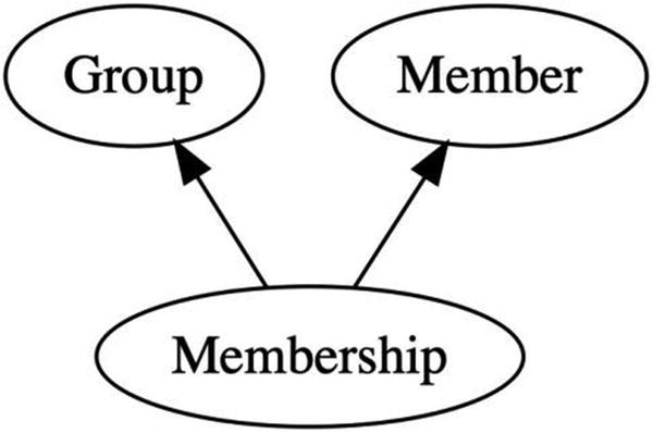
Membership is a successor of both the group and the member
Example
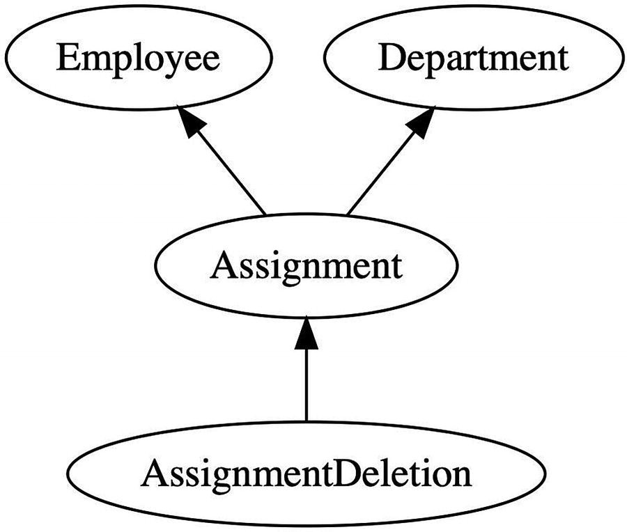
An employee is assigned to a department and subsequently removed
Consequences
The model cannot enforce the business rule that an entity belong to only one group. There is no mechanism that prevents two membership facts from having the same entity predecessor. In a relational model, a uniqueness constraint could enforce that requirement. But a uniqueness constraint on one node does not prevent an insertion on another. A uniqueness constraint cannot be enforced in an eventually consistent manner across multiple nodes.
Creation and addition to a group are not an atomic process. In the Ownership pattern, the parent is created before the entity. In Membership, however, membership is created after the entity. If the only queries that reach the entity are through membership, then this has little consequence. However, if there is another query that reaches the entity, it may be observable as an orphan for an indeterminate period of time. If the application developer wishes to hide orphans, they should add an exists clause to the query.
Related Patterns
If the model requires that the entity be a member of only one group, and that group cannot change, then consider using the Ownership pattern instead.
If the model requires that membership in one group be replaced with membership in another group, then consider applying the Entity Reference pattern. Model membership the group as a reference to the group fact, superseding prior references for the same entity. While this will not prevent concurrent changes, it will at least make removal from one group and addition to another an atomic operation.
Mutable Property
Represent values that change.
Historical facts are immutable. They do not change. Yet users expect to be able to change properties. The Mutable Property pattern represents changes to properties over time using only immutable facts.
It is desirable in a distributed system for nodes to be able to act in isolation. A user should have the autonomy to change a property without requiring a connection to any other node. The user might be on a mobile phone that is temporarily disconnected from the server. Or it might simply have a slow network connection, and the latency of performing a connected update would be undesirable.
With capability of autonomous change comes the possibility of conflicts. The disconnected user might change the same property as someone who is connected. Or two users on a slow connection might change the same property at more or less the same time. When each of their changes propagates to the other, the conflict will be detected. The system needs to include the capacity for resolving those conflicts.
Structure
A mutable property is represented as a fact having the entity as a predecessor and the value as a field. To keep track of changes over time, it records prior versions in a predecessor set.
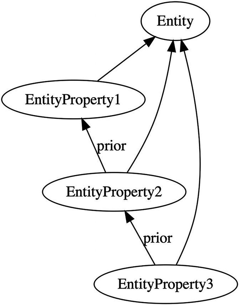
In a chain of versions, each points back to its immediate predecessor
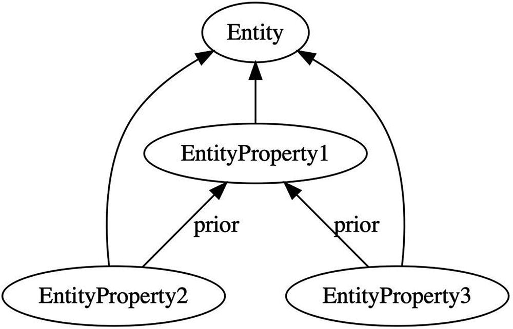
Concurrent changes result in multiple leaves
When a node computes a tree with multiple leaves, it recognizes a concurrent change. In this situation, the application will typically present all leaves as candidate values. Each leaf represents a value that was concurrently set for the property and has not been superseded. The user can select among the candidate values and resolve the dispute.
Alternatively, an application can compute a resolution on its own. This is usually accomplished via a simple function over the leaves, such as a maximum. In rare situations, however, the application developer may choose to base the resolution on the nearest common ancestor of all leaves. One example is a source control system like Git that computes a three-way merge. Such a complex function is not appropriate for most applications.
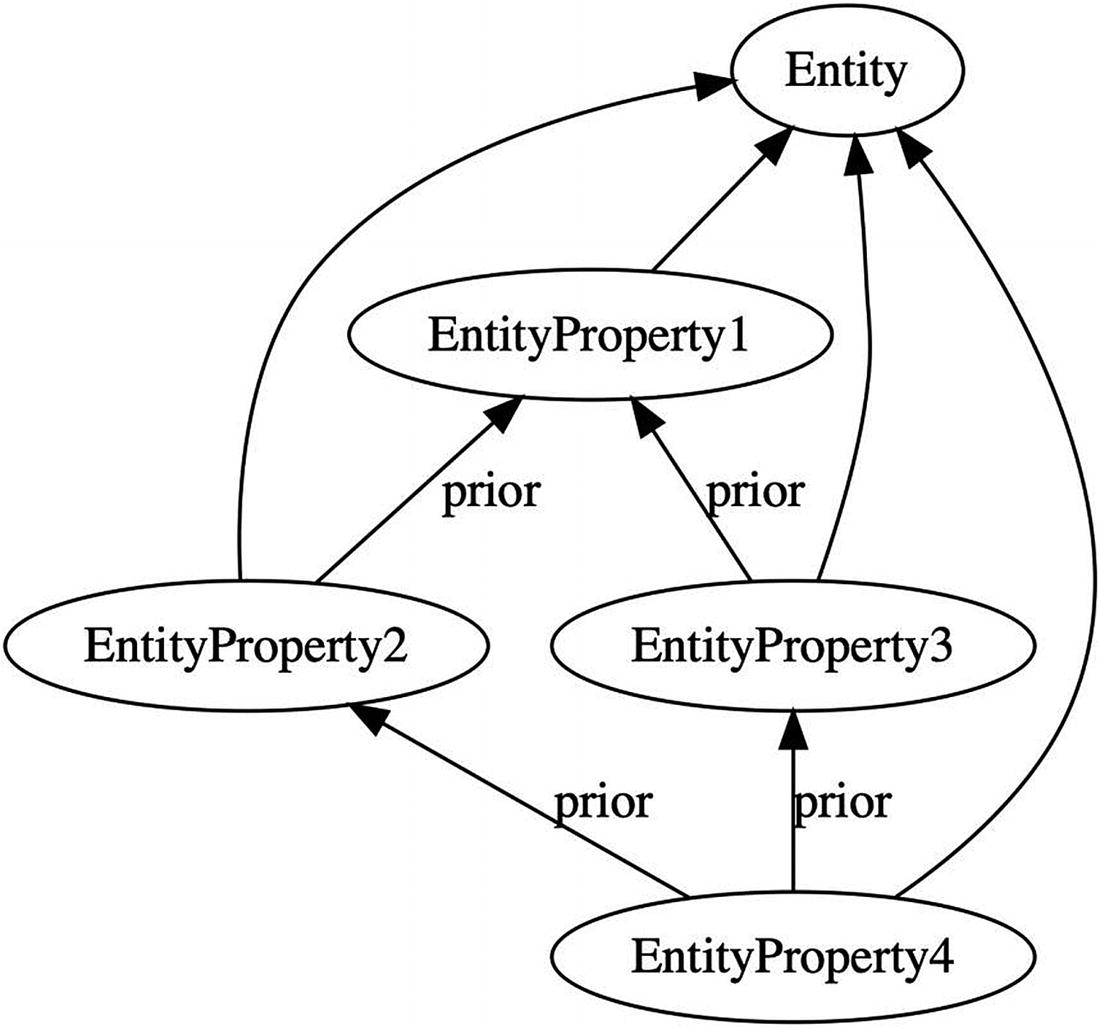
Concurrent changes result in multiple leaves
If the query returns one fact, then that fact represents the most recent version. If it returns many facts, then they represent the leaves and can be used as candidate values.
A property does not have to have a single value field . It is not uncommon for multiple values to change as a unit. In Domain-Driven Design, this situation arises when a property uses a value type. In these situations, all of the components of the value type appear as fields in a single property fact.
Example
If the query returns one fact, then that represents the most recent billing address. If, however, it returns multiple billing addresses, then concurrent changes have occurred and the facts represent the candidate billing addresses. The application presents all candidates to the user so that they can research and resolve the issue.
A similar query gets the latest shipping address. While it is unusual to change only one part of an address at any given time, it is not uncommon to change only the shipping address or only the billing address. That is why the application developer chose to make them separate facts.
While concurrent changes to billing address will result in multiple leaves, concurrent changes between billing address on one side and shipping address on the other will not. The system will simply present the most recent billing address beside the most recent shipping address. This reflects the intent of the application developer, as expressed by the decision that shipping and billing address have no causal relationship between them.
Consequences
Nodes observing the Mutable Property pattern can act autonomously. They can record a new value for a property without first connecting with any other node to prevent concurrent changes.
Said another way, concurrent changes cannot be prevented. There is no mechanism within a historical model that would ensure that only one change can be made at any given time. Properties can neither be locked nor serialized.
Nodes will recognize that concurrent changes have occurred post facto. All nodes will eventually receive the same graph, compute the same leaves, and therefore come to the same conclusion. Concurrent changes do not result in conflict.
When a user attempts to modify a property, the application should first verify whether the value has actually been changed. The application might, for example, display a dialog box with “OK” and “Cancel” buttons. The user might click “OK” even if they made no change. If the application created a new fact without checking whether the value had changed, it would create an unnecessarily complicated history.
The mutable property fact should not contain any auditing information. This allows two different users to change a property to the same value without introducing a concurrent update. If the fact contained, for example, the user or timestamp, then two concurrent changes to the same value would appear as distinct facts. The result would be an unnecessary merge between similar changes.
The response to multiple leaves must be based only on the information in the facts themselves. It must not be based, for example, on the order in which the facts arrived at the node. The result is a function that is commutative and deterministic; it computes the same result at every node regardless of message order. That is why the results of queries are unordered sets and not ordered lists.
If a node computes a resolution to a concurrent change, it must do so only on read. It must not attempt to create a new fact to resolve the concurrent changes. To do so would be to introduce the possibility of a never-ending storm of concurrent resolutions. Consensus algorithms such as Paxos are carefully constructed to avoid these resolution storms, but without such careful consideration, storms can easily arise. At any rate, strong eventual consistency demands convergence without consensus. This is achievable if all nodes run the same deterministic function on read.
The Mutable Property pattern cannot guarantee that a property has a single value. The query will always result in a set. Applications must be written to expect that that set might have multiple values. While it is sometimes tempting to introduce a location-specific rule to prevent concurrent updates—only one user is allowed to change a property, or only one node can be used to make that change—such rules are ultimately difficult to enforce and impose undesirable constraints on the system.
A query for the current value of a property could return an empty set. This represents the situation in which the property has not been initialized. On remote nodes, this could also indicate that the entity has been transmitted, but its initial properties have not yet arrived. Creation of an entity is not atomic with initialization of its properties. If an application developer intends to present only entities that have been initialized, they could add an exists clause based on the property fact.
Related Patterns
If the mutable property represents a relationship with another entity, the pattern becomes an Entity Reference .
Entity Reference
Represent a mutable relationship between entities.
Where Ownership and Membership are strict grouping constructs, some relationships between entities are simple references. These references don’t imply any kind of belonging or grouping, but rather just an association.
An entity reference is a property that points to another entity. In Domain-Driven Design, the referenced entity is typically an aggregate root , possibly in a different bounded context. In an object-oriented language, the entity reference is a pointer to another object. And in a relational database, it’s a foreign key. The reference is typically mutable and often will be initialized to NULL .
A relational database will use foreign keys to represent Ownership, Membership, and Entity Reference. To distinguish among them, first, look to the cardinality. A many-to-many relationship typically denotes Membership. A one-to-many relationship that has a cascade delete constraint represents Ownership. A less constrained one-to-many relationship—especially one that allows NULL—is probably an Entity Reference.
Structure
The distinction between the primary and referenced entity is an important one. The primary entity is the one with the reference property. Creating a new EntityReference fact changes the value of that property for the primary entity. The prior set will include other EntityReference facts that refer to the same primary entity.
Example

Two versions of an order line, each referencing a different product
This similarity between the two queries makes them behave atomically. When an order line is changed to reference a different product, both of the queries are affected. The first query will no longer return the previously referenced product, and the second query will no longer return the order.
Consequences
Just as with the Mutable Property pattern, an Entity Reference cannot guarantee that only one entity is referenced. The query for the current reference returns a set. An application must respond appropriately to a set larger than 1. This represents a concurrent update of entity references.
The results of the query could also be the empty set. This could occur—just as in Mutable Property—when the reference has not yet been initialized. But it could also occur when the reference has been set to NULL.
Related Patterns
This is a variant of the Mutable Property pattern in which the value of the property is a reference to another entity.
This is sometimes used as an alternative to the Membership pattern to indicate that an entity should be a member of only one group. While it cannot enforce that rule, it at least makes the transfer from one group to another an atomic operation.
Workflow Patterns
While CRUD operations make up an important part of business application development, they do not tell the entire story. The next set of business operations to consider are concerned with taking entities through a workflow. Workflow is typically the realm of business process modeling, state transition diagrams, and flow charts. It is the study of collaborative steps that move work from inception to completion.
Tracking the flow of work through a system that allows mutation is an exercise in frustration. If each step of the process has the potential to change the work item, then reasoning about the behavior of the system requires careful analysis of all possible permutations. Allowing for parallel execution, mutability often leads to race conditions.
But within an immutable architecture, workflow is a much simpler process. It begins with capturing the work to be performed in an immutable object. Any further changes to the source object are ignored. Then, we set up a query to identify which work items are ready for any given process. Finally, we capture the outcome of that process in an immutable way that atomically moves the work item along to the next step.
Adding workflow to an application turns it from an anemic forms-over-data model into a system that can assist with communication among collaborators. Not every subdomain of an application needs workflow, but the most central bounded contexts that provide the most business value often do.
Transaction
Capture a known state of an entity to perform an atomic unit of work.
The structural patterns that we just explored allow an entity to change over time. The changes are captured as immutable facts, but the accrual of new facts as the user interacts with the system simulates changes to an entity. At some point, the user will decide to take some action. Any further changes to the entity after that point should not affect that action.
Users might be adding items to a shopping cart. They can remove items, replace them, and restore them back to the cart. They can change the quantity, product, shipping options, delivery address, and any other property. The structural patterns in the previous section allow those operations.
But then when the user submits the order, the items and all of their properties should be locked down. No additional items can be added, and no properties can be modified. Processing may begin at any time, and a change to an order in flight would be disruptive to business.
The Transaction pattern takes advantage of immutability for business processing. It records the information about a request for work in such a way that it cannot be modified after work begins.
Structure
A Transaction identifies as a predecessor an entity that it is acting upon. Whereas that entity was originally a starting point for children, mutable properties, and other successors, the transaction now seeks to lock it down. It does so by inverting the predecessor/successor relationship.
Where Ownership placed the parent as a predecessor of its children, Transaction makes children predecessors of parents. Successors can be added over time, but predecessors are immutable. Recording children as predecessors prevents further creation or deletion.
The transaction also identifies the specific versions of Mutable Properties. These become direct or indirect predecessors of the transaction. Again, the relationship is inverted so that any further modifications to those properties do not affect the transaction.
The transaction and all of its items are captured at a single machine. This is typically the workstation that the decision maker is using. When a user decides to issue a transaction, the system captures the state of the objects as they are known to that user at that time. Creating a transaction does not require the machine to communicate with any other node, as all of the information required is local.
Example
When a customer submits an order, they lock down its current state. They cannot make further changes to the order. They can only request a subsequent return and new orders.

An order submission inverts the model to lock in predecessors
Any lines that have been deleted are not included in the OrderSubmission. Other lines might be subsequently deleted, or deleted lines later restored. Neither change will affect the OrderSubmissionLines that have been captured.
All of the arrows point out of the OrderSubmission. All of the information required to process the order can be found by traversing the graph in one direction. Given an OrderSubmission, any node will compute exactly the same order. This locks in the items, products, and quantities.
Consequences
Once a transaction is recorded, subsequent changes to the entities or properties will have no effect. All of the information in the transaction is recorded in predecessor relationships. Predecessors are immutable, so the transaction is locked down.
All nodes receiving the transaction see it in exactly the same state. The identity of a fact includes the identities of its predecessors. Any difference in predecessors such as transaction items or property versions would necessarily result in different facts.
A transaction is processed atomically. Items may arrive at a node ahead of their transaction. But processing begins with a query for a transaction, not an item. Items will remain dormant until the subsequent transaction arrives, at which time all items will take effect simultaneously.
All necessary information must be in the transitive closure of the transaction. Starting at the transaction fact, follow all predecessors. From those facts, recursively follow their predecessors. The transitive closure is the set of all facts thus visited.
Related Patterns
The Transaction pattern inverts the predecessor/successor relationship found in the Ownerhship and Mutable Property patterns.
A transaction is often placed in a Queue or an Outbox, and is usually associated with a Period.
Queue
Manage work to be processed manually.
Work that a person needs to handle is often presented in a list. The user interface shows the user a set of work items that requires their attention. The user selects a work item and navigates to part of the application where they can handle it.
The user might get interrupted. So the work remains on the queue until they actually complete it. If another user observes the queue, they will be able to see the same work item.
The Queue pattern presents a set of work items that are ready for manual processing. It ensures that a work item is removed from the queue when it is completed.
Structure
In the process of performing the requested work, the user will create an Action fact . The action records the outcome of the work.
Because the action appears in the not exists clause, the work item is removed from the query once the action has been performed. Recording the action and removing work from the queue occur in a single atomic operation.
Example

An order submission triggers both the request for delivery and the packing slip
Once the order is picked, the shipping manager prints a packing slip. The act of doing so removes the order from this queue.
They call for a truck and then enter the RequestForDelivery into the system. Once they do so, the order no longer appears in the query. It has been removed from the queue.
We have deliberately chosen not to have a predecessor/successor relationship between RequestForDelivery and PackingSlip . The delivery request can be made before the product is picked. Or, based on volume, the warehouse might find themselves backlogged and choose to delay the request for delivery.
The creation of a PackingSlip atomically moves the work from the shipping manager’s queue into the logistics queue. The subsequent creation of the RequestForDelivery removes it from the logistics queue.
The packing slip is not a hard prerequisite. It is not a predecessor of the request for delivery. But by switching from one queue to another, the company can adjust its business process to better respond to circumstances.
Consequences
The action performed on a work item is used in the not exist clause of the queue. As a result, recording the action and removing the work item from the queue is a single atomic operation.
Unlike a FIFO (first in first out) queue, the queue query does not impose an order on the work items. The results of a query are a set, not a list. If order is important, place a timestamp on the work item fact. Use that timestamp to order the set for presentation to the user.
Related Patterns
If work is to be performed automatically instead of manually, then the Outbox pattern is more appropriate.
Work items in a queue are often Transactions.
Work items are often grouped by unit of time. This recognizes a natural period that the business already recognizes. Application of the Period pattern has the extra benefit of preventing the queue query from slowing down as history accrues.
Period
Bound the accrual of facts with discrete time slices.
The time required to query a historical model is governed by the number of successors that the starting point or intermediate fact has. If we start each query from the root of the graph, those queries would get slower over time. Starting further down the graph at a fact that has a bounded number of successors will keep performance constant as we accrue more facts.
Any feature of the system that limits the number of successors is a good candidate for subdividing the graph. The one that is most readily available is time. The Period pattern subdivides the historical graph by discrete units of time. While the total number of facts is expected to grow, the number per unit period will remain somewhat more bounded.
In addition to the performance benefits, associating facts with a period often captures an important business concept. Accountants tend to close their books on daily, monthly, and quarterly periods. They do this not just to limit the size of a ledger but also to give themselves reporting boundaries. The Period pattern seeks to do the same with application data.
Structure
Typical choices for the discrete time unit are calendar or business day, month, quarter, or year. For high-throughput systems, units may go down to the hour, but rarely smaller.
Results from two or more queries are unioned together to produce an overlapping query. The overlap is chosen to allow plenty of time for remote nodes to connect and share their work items and for those work items to be processed before the period rolls off.
The period has no additional fields, so that the owner and discrete unit of time produce a unique fact. All nodes creating work items produce the same fact. And each query for work items creates the starting point in the same way.
Periods are sometimes captured hierarchically. The largest period—say a year—falls directly under the owner. The next period down—for example, a quarter—has the larger period as a predecessor. Periods organized in this way must share a boundary; month and week cannot be organized in a hierarchy. This is usually done for reporting rather than performance reasons.
Example
In the previous example, we added order submissions directly to the company. As time passes, the system searches more orders within the company to find the ones that have not yet been picked or shipped. We can make things easier on the system and record an important dimension of the model at the same time.

An intermediate fact groups orders submitted to a company by date of business
Date of business is not strictly determined by the computer clock. An order may be counted toward the next date of business if it is placed after hours, or if it occurs on a weekend or holiday. In fact, the company may even choose a policy wherein orders placed after 3:00 are associated with the next date of business. The period is an operational construct, not a physical one.
Not all nodes need to advance to the next period at exactly the same time. There is no need to rigorously synchronize the clocks across the workstations on which users are submitting orders. If one workstation starts submitting orders into the next date of business while another workstation remains on the current one, then those orders are simply counted in different periods. This will not cause any problems as long as there is no causal relationship between the order submissions. And the fact that the developer chose not to make one OrderSubmission the predecessor of the other indicates that there should be no causal relationship.
We run this query for two dates of business—the previous one and the current one—and union the sets. Any given order submission occurs in only one date of business, as indicated by the singularity of its predecessor, so this practice does not risk duplication. But the overlap does prevent us from missing orders. As long as the period is significantly longer than the SLA, we will have received and processed a day’s orders before we roll the query forward too far.
Consequences
A work item should have only one associated period. If a unit of work is broken into smaller units, and those each have their own period, then it would be possible to split the work between two periods. Think of a train moving across a switch at the same time that the switch is thrown. If the cars are not connected, then there is no problem. But if they are attached to one another, this could cause some unintended consequences.
Two or more periods should be queried for work items. The overlap provides a buffer of time for work items to arrive and be processed. If upstream nodes can be offline, the number and duration of overlapping periods must be chosen to allow them to reconnect. As long as the expected time to receive and process work items is significantly shorter than the duration of overlapping periods, then work will not typically be lost.
There is no mechanism in the model to guarantee, however, that work won’t be delayed beyond the oldest period queried. The processing system should be flexible enough to be manually reset to pick up lagging work items. A query from the Owner one predecessor higher than the period can encompass all periods. While this query would be slower, it would look back in time for any missed work items. A business decision can then be made to determine the best corrective action.
Related Patterns
Periods are often used as the starting point for queries in the Queue or Outbox pattern. An unbounded queue gradually becomes a performance problem. But a queue bounded by the expected number of work items per period is much easier to manage.
The work items within a period are often Transactions.
Outbox
Send work to an external system that does not follow immutable architecture principles.
Distributed systems are heterogeneous. Components designed with differing architectural constraints will need to interact with one another. We will find ourselves sending requests from an immutable system into a location-dependent system.
At the boundary between immutable and location dependent, we have an API. The immutable system runs a service that calls the API whenever a fact appears in a Queue. It then records the results of that API call in a new fact that removes the work from the queue.
A single instance of a service would be easy to implement, but it would ensure neither high availability nor high throughput. For those properties, we need redundancy. And that’s where implementing a service gets difficult.
When sending work to a location-dependent API, it is often beneficial to limit the number of duplicate requests. If the system is not idempotent, it might incorrectly duplicate the work. If so, we would like to ensure—as nearly as we can—that requests are sent exactly once. But even if the downstream system is idempotent, multiplying every request by the number of parallel services is unnecessarily wasteful.
The Outbox pattern provides a mechanism by which parallel services avoid sending duplicate work requests to third-party systems. It cannot prevent duplication altogether, but it can take steps to reduce them.
Note that there is no corresponding Inbox pattern. When information is received from an external system, it is simply turned into a fact. No special conversion pattern is necessary in this direction.
Structure
The Outbox pattern integrates with location-dependent services by becoming location-dependent itself. Unlike the other patterns presented here, this one is not implemented entirely within the rules of immutable architecture. Instead, it uses a location-specific journal to keep track of successful API calls.
Journaling
The journal records the result of API requests made to the remote system. The index into the journal is the hash of the work item fact that triggered the API call. The journal contains all pertinent data received from the API. It only records successful API calls.
- 1.
Receive a work item fact from a queue query.
- 2.
Call the API.
- 3.
Store the results of the API call in the journal.
- 4.
Create a fact with the results of the API call.
The fact created in step 4 also has the effect of removing the work item from the queue. The next time the service runs the query, the work item fact will not be present. This is the “happy path.”
When things don’t work correctly, the service may fail partway and find itself repeating these steps. The journal is intended to reduce the probability that the API will be called more than once. It does so by providing a way to skip the API call in step 2 in some failure scenarios.
After a service receives a fact (step 1), it checks the journal for a matching row. The journal is indexed by the hash of the work item fact. If a matching fact is found, then a previous or parallel invocation of the service had completed step 3. The service reads all of the information about the result of the API call and proceeds to step 4 to create the fact.
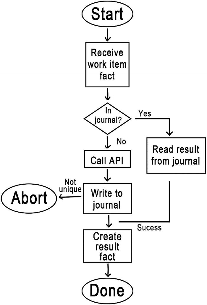
Journaling reduces the likelihood of duplicate API calls
Random Processing Delays
Journaling reduces the chances of duplicate successful API calls, but it does not prevent them. One of the ways in which duplication can still occur is for two nodes to run the service on the same work item in parallel. We can take additional steps to make parallel execution less likely.
The simplest way to reduce the likelihood of parallel execution is to introduce a random processing delay. Consider a service that uses polling to query the queue for work items. It wakes up at regular intervals and runs its query. If it finds some work items, it processes one of them and runs the query again. It does not process all of them, because doing so adds time during which a different service could wake up and run the same query. It simply selects one work item at random and leaves the rest in the queue.
We can configure all of the nodes to wake up the service on the same schedule. Perhaps we simply create a cron job that runs once a minute. But, to reduce the likelihood of parallel execution, we wait a random number of seconds before running the query.
This is a very simple technique. Combined with the journal and a relatively fast downstream API, it can be quite effective. But it is only appropriate for low-throughput interfaces. It introduces unnecessary latency and limits the frequency with which work items can be processed.
Rendezvous Hashing
When low latency and high throughput are required, a more sophisticated mechanism can be employed. Rendezvous Hashing 2 is a technique for uniquely allocating objects to nodes. It is often used in distributed caches. We will adapt it to instead allocate work item facts to services. A similar algorithm—Consistent Hashing3—can be adapted just as well.
To begin with, each service instance generates a random number when it starts up. It registers its number with the other services. The service registry could be implemented with a gossip protocol, a distributed hash, or even the same database that is used to keep the journal. The only requirement is that the other services become aware of this new member shortly after the service comes online.
Once it has registered, a service subscribes to new work items entering the queue. Unlike the random processing delay solution, services do not poll. They are notified via webhooks, broadcast, or a publish–subscribe message queue as soon as work is available. Which mechanism they use depends upon your chosen communication infrastructure.

A node computes weights for one work item to determine the winning service
All services will compute the same weights for a work item. They will therefore all select the same winner. Only that winner will process the work item, resulting in less chance of parallel execution .
Service Failure
Unfortunately, nodes fail. When a service stops responding, its work items will remain in the queue longer than expected. Fortunately, the other services can detect this.
Since all services compute the weights for all work items, each service can see where it falls in the rank. If a service determines that it is the second-place winner, then it keeps track of the work item. If it sees it again after a timeout, then it assumes that the first-place winner has failed. It processes the work item and removes the failed node from the registry.
If a service that has not failed finds itself removed from the registry, it just creates a new random number and comes back in. The timeout should be high enough to make this scenario unlikely, but low enough that failures don’t go undetected for too long.
Failure detection can be generalized beyond the second-place winner. Third-, fourth-, and higher-place winners can set longer timeouts on the work items. This will mitigate against a simultaneous failure of multiple services, as such would be caused by an infrastructure or network outage.
Example
With that in place, we create a service that subscribes to this queue. As a service starts up, it generates a random number and inserts a record into a shared Redis cache. When a new OrderSubmission is created, the node that created it broadcasts a notification. The service subscribes to that notification to learn about new work items.
Upon notification, the service runs the query to find work items. It pairs the hash of each work item with the random number of each service in the Redis cache. It hashes this pair to compute the weight of that work item for that service. All of the work items for which the service itself has the highest weight continue to the next step.
The service checks a shared SQL database for a journal entry by that work item’s hash. Finding none, it makes the API call and inserts the resulting invoice number into the journal. After that insert succeeds, it creates an Invoice record containing the returned invoice number.

Services share a distributed cache and persistent table to support the Outbox pattern
Consequences
There is no guaranteed mechanism to prevent duplicate calls to a third-party API. Even with this pattern in place, duplication will occasionally happen. Downstream services should be coded to be idempotent.
Upon service startup, a delay in notifying other services leaves open a window in which both could believe themselves to be the first-place winner. To mitigate against parallel processing in this scenario, delay processing by the new service until enough time has passed for all other services to finish processing any work items in flight.
The fact generated from the results of the API call must not contain any information not captured in the journal. If it contains, for example, auditing information such as the timestamp or IP address when and where it was recorded, then the fact would be different from other facts representing the same API call. The model would contain duplicate data even when the journal prevented duplicate API calls.
Related Patterns
For manual processes, present a Queue to the user using a simple query.
The work items in the outbox are typically Transactions .
The query for the outbox usually begins at a Period. Overlap periods by significantly greater than the downstream SLA to prevent loss of work items.
Designing from Constraints
The patterns presented here are a starting point for building applications using only immutable historical facts. They emulate—as closely as they can—the behaviors that people have come to expect from business applications. And they do so using only the capabilities of immutable distributed data.
Where these patterns diverge from expected behavior, they reveal constraints about the medium in which they are rendered. A Mutable Property cannot have a single value. And we cannot enforce that an entity have Membership in only one group. Those truths reveal that the application is distributed across several nodes, each of which has autonomy to capture concurrent changes. Also, we cannot say for sure when a Period is closed. We can only assume that enough time has passed to allow distant nodes to connect and share their work items.
We cannot give the users of our applications exactly what they have come to expect from centralized systems. The rules of immutable architecture prohibit it. The reason is simple; those promises cannot be kept in a strong eventually consistent manner. Architectures that nonetheless provide these behaviors must compromise some aspect of their distributed nature in order to do so.
An application built according to these patterns acknowledges the constraints imposed by distributed nodes. It starts from those constraints and builds toward expected behavior, never promising more than what can be reasonably delivered.
These patterns are more than guidance on how to build a distributed application; they are a means of communication. They make it possible for application designers to talk to stakeholders about constraints without first teaching them about strong eventual consistency and the CAP Theorem. They permit us to speak in generalities without reasoning through specific scenarios in which distributed nodes might cause us problems. They frame a conversation about application design that helps all participants set expectations and keep them.