
A Synthesis
In this book we have discussed many aspects of VHDL and looked at examples of its use. One very strong motivation for using VHDL is hardware synthesis. The idea behind synthesis is to allow us to think of our design in abstract terms. We need not be so concerned about how best to implement the design in hardware logic-that is the job of the synthesis tool. It converts our abstract description into a structural description at a lower level of abstraction.
This appendix offers a brief introduction to synthesis, based on the IEEE standards that cover synthesis of VHDL models. A full coverage of the topic warrants a complete book in its own right. We refer the interested reader to the large number of books on hardware synthesis (for example, [1]).
There are several synthesis tools available from different design automation tool vendors. While many of them perform the same general process, they differ in their command sets and the way in which we specify synthesis constraints. Hence we discuss synthesis tools only in very general terms. More importantly, synthesis tools differ in the subsets of VHDL that they accept as input. The majority only accept designs described at the register-transfer level and synthesize to circuits composed of gates and flipflops. A small number of behavioral synthesis tools accept designs described at a higher level of abstraction. However, at the time of writing, behavioral synthesis technology is still immature and not widely adopted.
The disparity between synthesis tools motivated the development of IEEE Standard 1076.6, Standard for VHDL Register Transfer Level Synthesis. This standard specifies a “lowest common denominator” subset of VHDL that should be acceptable to most synthesis tools. The intention is to assist designers in writing models that are portable between synthesis tools and to ensure that the behavior of the synthesized designs matches simulation results. In this appendix, we discuss the subset restrictions described in the 1999 version of the standard. Future versions will define less restrictive subsets.
A major restriction specified by the 1999 version is that models be written using VHDL-87. The reason is that, at the time of development of the standard, the most widely used synthesis tools had still not been updated to accept VHDL-93 syntax. The reader should refer to Appendix F for a summary of differences between VHDL-87 and the subsequent versions of the language.
A. 1 Use of Data Types
The synthesis standard restricts models to use only the following data types:
Scalar Types
Models conforming with the synthesis standard may define and use enumeration types, with some restrictions. The predefined types boolean and bit and the standard logic types std_ulogic and std_logic are implemented in hardware as individual bits. User-defined enumeration types may be implemented by a tool-dependent encoding. Alternatively, we may specify the encoding by decorating the type with a string attribute, enum_encoding, which we declare as follows:
The value of the attribute in an attribute specification for an enumeration type is a sequence of bit-vector literals, representing the encoding for the enumeration values in the type. For example, given an enumeration type for states in a finite-state machine, we can define the state encoding as follows:
The bit vectors correspond in order to the enumeration values in the type definition. All of the literals must contain the same number of bits, and underscore characters may be included to enhance readability. Note that we should ensure that the enumeration values are listed in ascending order of their encodings. Otherwise synthesized relational operations may not produce the same results as relational operators evaluated during simulation.
Models conforming with the synthesis standard may also define and use integer types. Values of these types are implemented in the synthesized design as vectors of bits. If an integer type includes only non-negative values, the synthesized vector uses unsigned binary encoding. If the type includes negative values, two’s-complement signed encoding is used. The number of bits in the encoding is determined by the range of values in the type. For example, given the following declarations in a model:
values of type sample should be implemented using 7-bit two’s-complement encoding, and values of subtype table_index should be implemented using 10-bit unsigned encoding. Synthesis tools conforming with the standard should support integers within the range –231 to +231 - 1, mapping to 32-bit two’s-complement encoding.
The remaining classes of scalar types, namely, physical and floating-point types, are not supported by the synthesis standard. Definition and use of such types in a model are ignored.
Composite and Other Types
Models conforming with the synthesis standard may define and use array and record types, but there are some significant restrictions on the use of array types. They must only be one-dimensional and must be indexed by an integer range. Furthermore, the index bounds must be static, so that the synthesis tool can determine how much storage or how many bits of data are required in the hardware. The element type can only be an allowed scalar type, as described above, or a one-dimensional vector of an enumeration type representing individual bits. Thus, for example, the following array types are permissible:

whereas the following are not:

The types unsigned and signed defined in numeric_bit and numeric_std are array types that meet the requirements for synthesizability, since they are one-dimensional arrays of elements that represent bits. The synthesis standard requires that we use these types if we need to represent unsigned or signed numbers at the bit level. We cannot use array types that we define in our model.
The synthesis standard does not support use of access types, file types or incomplete type declarations. Synthesis tools should ignore their declarations and are not required to accept models that use access-type values or file operations. In particular, dynamic allocation of objects using the new allocator and deallocation of objects using the deallocate procedure are not supported. The synthesis standard does support declaration of subtypes, but ignores user-defined resolution functions within subtype indications.
A. 2 Interpretation of Standard Logic Values
If we use the standard logic types std_ulogic or std_logic in our models, we need to consider how a synthesis tool interprets values of different driving strength and unknown values. The synthesized hardware deals only with logic 0 and 1 values. We use standard logic values other than 0 and 1 to simulate the effects of weak driving strength and indeterminate logic values. The synthesis interpretation of these metalogical values is defined in IEEE Standard 1076.3.
When our model assigns to a signal a value calculated by an expression from other signal values, the synthesis tool generates a hardware circuit that implements the logic of the expression. However, when our model uses a literal standard logic value, the synthesis tool must represent the value as either a logic 0 or a logic 1. The synthesis standard specifies that the standard logic values ‘0’ and ‘L’, like the bit value ‘0’ and the Boolean value false, are represented as a logic 0. Similarly, the standard logic values ‘1’ and ‘H’, like the bit value ‘1’ and the Boolean value true, are represented as a logic 1. Thus the synthesis tool does not attempt to interpret the strength information associated with the standard logic value.
When our model assigns the standard logic value ‘Z’ to a signal, the synthesis tool generates a tristate buffer for the signal. Usually such an assignment is nested within a conditional statement. In that case, hardware generated for the condition is used to enable or disable the tristate buffer. For example, the if statement

would result in synthesis of a tristate buffer driving request. The input to the buffer would be connected to ready, and the control signal to enable the buffer would be connected to request_enable. When our model uses ‘Z’ in contexts other than a signal assignment (for example, in a comparison expression), the synthesis tool treats it in the same way as a metalogical value.
Use of metalogical values in a model is either ignored or not accepted by the synthesis tool, depending on the context. When values are tested for equality with metalogical values, the result is deemed to be false. Similarly, a test for inequality with metalogical values is deemed to be true. The rationale is that real hardware values are known to be either logic 0 or logic 1, so it does not make sense to synthesize hardware to compare with any other values. Thus any statements controlled by an equality comparison with a metalogical value, such as statements nested in an if statement or a case statement, can be ignored by the synthesis tool. They exist in the model purely for simulation purposes. In the cases of metalogical values appearing as operands of other relational operators and of arithmetic, logical and shift operators, the synthesis tool should not accept the model.
The std_match function defined in the numeric_std package can be used to compare standard logic values and vectors. It has the advantage of producing the same results in simulation and synthesis, unlike comparison using the “=” operator. Synthesis tools represent the use of std_match by an equivalence test. Simulation tools perform the comparison ignoring the driving strength of the parameters. If both values represent the same logic level, the comparison returns true. If either value is a metalogical value other than the comparison returns false. The value is interpreted as “don’t care", so comparison with it returns true. Synthesis of a comparison using std_match with a literal vector containing “don’t care” elements results in comparison hardware that excludes the “don’t care” bits from the comparison.
A. 3 Modeling Combinatorial Logic
Combinatorial circuits are those in which the outputs are determined solely by the current values of inputs; the circuit does not maintain any internal state. The simplest way to model combinatorial logic in synthesizable VHDL is using concurrent signal assignment statements. For example, we can model a Boolean function of inputs as follows:
A synthesis tool would generate hardware composed of a comparator for the input signals sample and limit, and a gate to combine the comparison output with the signal ready. It may optimize the hardware to meet timing and area constraints, but the result would perform the same function.
We can use a selected signal assignment statement to describe a multiplexer, for example:
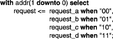
We could also have expressed this behavior using a conditional signal assignment statement, as follows:

However, in a conditional signal assignment, the conditions need not be mutually exclusive, so the synthesis tool would infer a priority-encoded chain of multiplexers to conform with the language semantics. This structure would be slower than a simple multiplexer. The tool may be able to optimize the hardware, but it is safer to use a selected signal assignment to imply a multiplexer function if that is our design intent.
One situation in which a selected signal assignment statement is appropriate is combinatorial logic with a tristate buffered output, for example:
We can also use a process statement to describe combinatorial logic. The process must be sensitive to all of the inputs, and the combinatorial outputs must be assigned values in all possible executions of the process. This form of process is most useful when there are multiple outputs, for example:

In this example, any change in any of the inputs results in new values being determined for all of the outputs. Thus the design is purely combinatorial. A synthesis tool would infer combinatorial network with tristate drivers on the outputs.
When we write a process that declares and uses a variable, a synthesis tool may infer a need for storage in the synthesized hardware. However, if all possible executions of the model in response to input changes involve the variable being assigned a value before being read, no storage is needed. Consider the following process as an example:

The process is sensitive to all of the inputs. There are two possible execution paths when an input changes. If sel is ‘1’, the value of a is assigned to operand and subsequently added with c to determine the output sum. Alternatively, if sel is ‘O’, the value of b is assigned to operand and added with c. Thus we can think of operand as representing the intermediate node in a combinatorial network consisting of a multiplexer and an adder. The value assigned to operand need not be stored.
A.4 Modeling Sequential Logic
Sequential circuits are those that maintain internal state. The outputs they produce in response to given inputs depend on the history of inputs received previously. Most sequential circuits we design are synchronous, or clocked. They use a rising or falling edge of a clock, or a level of an enable signal, to control advance of state or storage of data. The synthesis standard supports descriptions of these kinds of circuits. Most current design methodologies prefer edge-triggered sequential design, since achieving correct timing is more straightforward. Occasionally we might design an asynchronous circuit: a sequential circuit without a clock or enable input. Such circuits store state using combinatorial feedback loops. The synthesis standard and most synthesis tools do not support synthesis of these kinds of circuits.
Unlike signals used for data, which can be of a fairly wide variety of types, clock signals are restricted to be of type bit, std_uiogic or a subtype such as std_logic. A clock signal need not necessarily be a single scalar signal; it may be a scalar element of an array of bit or std_ulogic values.
Modeling Edge-Triggered Logic
The synthesis standard prescribes use of a number of templates for processes describing edge-triggered sequential logic. One of the simplest of these is

The clock-edge expression is an event expression. For a rising clock edge, it must be of one of the following forms:

For a falling clock edge, it must be of one of the following forms:

The sequential statements appearing within the if statement must not include any wait statements or references to clock-edge expressions.
We can use the template as the basis for a simple edge-sensitive register, for example:

The simple template can be augmented to include level-sensitive asynchronous control, such as reset, preset or asynchronous load. The template is

The Boolean conditions implement the asynchronous control by referring to signals other than the clock listed in the sensitivity list. All signals read in the conditions and the sequential statements governed by the conditions must be included in the sensitivity list. None of the sequential statements in the process may be a wait statement, and the only reference to a clock-edge expression is the reference in the final eisif clause.
An example of use of this template is a counter with asynchronous reset and load:
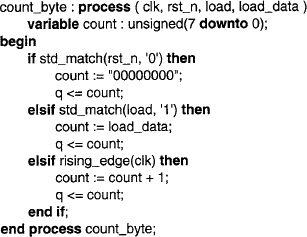
This counter is controlled asynchronously by the signals rst_n and load; hence they appear in the sensitivity list. The signal load_data is sensed in a statement governed by one of the asynchronous control conditions, so it too is included in the sensitivity list. Note that the order of condition tests determines the priority of the asynchronous control signals. In this example, the reset condition has priority over the load condition. If both control signals are asserted at once, the counter is reset rather than loaded.
The remaining template for edge-triggered sequential circuits uses a wait statement to implement sensitivity to the clock edge. The template is

In this template, the clock-edge expression can take any of the forms listed above or one of the following additional forms:
The wait statement containing the clock-edge expression must be the first statement in the process body. There must not be any other wait statements or references to clock edges in the body, nor in any procedures called from the process.
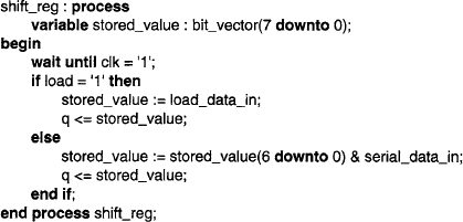
Because the wait statement must be the first in the process, we cannot use this template if we need asynchronous control. However, its relative simplicity makes it useful in cases where we only need synchronous control. As an example, the following process models a shift register with synchronous load:
Level-Sensitive Logic and Inferring Storage
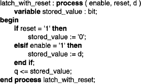
Level-sensitive sequential logic maintains state, but does not respond to clock edges. Instead, state is usually updated under control of an enable signal. While the enable signal is asserted, the state can change according to data inputs. While the enable signal is negated, changes on the data inputs are ignored and the circuit maintains its current state. In some synthesizable models, we do not explicitly represent the storage for the state. Instead, the synthesis tool infers the storage from the model behavior. Consider the following model for a transparent latch:

This process is sensitive to changes on the enable and d inputs. If enable is ‘1’ when either input changes, the data value is used to update the output q. If enable is ‘O’, the current value is maintained on q. This behavior is implied by the semantics of signals and signal assignment in VHDL. When the synthesis tool implements the model as a hardware circuit, it must provide some storage to maintain the value for the output. The tool must infer the need for storage from the model semantics.
There are two general cases when the synthesis tool must infer storage for a process that does not include a reference to a clock-edge expression. In both cases, the process must include in its sensitivity list all signals that the process reads. The first case arises if there are possible executions of the process that do not involve assignment to a signal or to a variable declared in the process. The latch example illustrates this case. If the process executes when enable is ‘O’, the assignment to q is bypassed, so storage is inferred for q. The following process is another example, involving storage inference for a variable:
In this example, the output signal q is assigned on every execution of the process, so no storage is inferred for it. However, the stored_value is not assigned when reset and enable are both ‘0’; hence storage is inferred for the variable.
The second case in which storage is inferred for a process that does not include a reference to a clock-edge expression arises if there are possible executions in which a signal or variable is read before being assigned. Consider the following erroneous process intended to describe a counter with reset:
The process is sensitive to changes of count_en. Whenever that signal changes, the old value of q is read and incremented to determine the new value. The value must be maintained until the next change of count_en, implying the need for storage for q, even though it is assigned in all possible executions of the process.
The synthesis standard recommends against writing processes in which signals or variables are read before being assigned. Usually such processes are not what we intend, and the inference of storage is inadvertent. On the other hand, a process in which a variable is first assigned and then read in all possible execution paths is legal and useful. Such a process simply models combinatorial logic, as we discussed in Section A.3, with the variable denoting an intermediate node in the combinatorial network.
Modeling State Machines
Many designs expressed at the register-transfer level consist of combinatorial data paths controlled by finite-state machines. Hence it is important to be able to describe a finite-state machine in such a way that it can be synthesized. The preferred style is to separate the implementation into two processes, one describing the combinatorial logic that calculates the next state and output values, and the other being a register that stores the state. Figure A-l shows an architecture body for a state machine described in this way.


FIGURE A-l An architecture body for a finite-state machine.
The architecture body defines an enumeration type for the state values. We can either rely on the synthesis tool to determine the encoding for the state or use the enum_encoding attribute to define our own encoding, as described in Section A.I. The signal current_state represents the output of the state register, and the signal next_state is the state to be assumed by the state machine on the next clock edge. The process next_state_and_output describes the combinatorial logic. It uses a case statement to determine the next state and output values, depending on the current state value. Note that the output out1 is uniquely determined by the current state. It is a Moore machine output. The output out2, on the other hand, depends on both the current state and the current inputs to the machine. It is a Mealy machine output. The process state_reg describes the state register. It has an asynchronous reset control input that forces the machine into the ready state. When reset is inactive, the process updates the current state on each rising clock edge.
A.5 VHDL Modeling Restrictions
In this section, we describe the restrictions, not otherwise described above, specified in the synthesis interoperability subset (IEEE Standard 1076.6). Recall that these restrictions are required for a model to be portable between different synthesis tools. Individual tools may be less restrictive than described here. Recall also that the standard requires use of VHDL-87.
Design Units
Entity declarations in a synthesizable model must not include any declarations. They may include passive process statements, but those statements are ignored by the synthesis tool. Since passive processes cannot include signal assignments, there is no need for any hardware to be generated for them. Any generic constants declared in the entity header must be of an integer type. This precludes use of generics to specify timing parameters for a design. Instead, timing constraints are specified using a separate command file input to the synthesis tool, and timing characteristics are derived from the synthesized model. The way in which this is done is tool dependent, so we do not discuss details here. The ports of the entity must conform to the data type restrictions described earlier, and any default initial values declared in the port list are ignored by the synthesis tool. In addition, a port may not be guarded; that is, it may not include the keyword bus in its declaration.
We describe the register-transfer-level structure and behavior of a design entity in an architecture body. While we can write more than one architecture body for a given entity, we can only make use of one in a particular design hierarchy. This follows from the restrictions on configuration declarations, discussed below. Any file or alias declarations, configuration specifications, disconnection specifications, attribute declarations and attribute specifications (except for the enum_encoding attribute) are ignored by the synthesis tool. We can include use clauses in an architecture declarative part, but they must only refer to package names or to names of items declared within packages. We cannot, for example, refer to an entity name in a use clause. Signals declared in an architecture body cannot be guarded; that is, their declaration cannot include the keyword bus or register. Furthermore, any initial value expression in a signal declaration is ignored. This corresponds to real hardware, in which the initial value of a signal is determined by the components driving the signal.
The use of configuration declarations is severely restricted by the synthesis standard. We may only write a configuration declaration for the top-level entity in the design hierarchy, and we may only use it to specify which architecture of the entity to use. We may not include use clauses or attribute specifications, nor may we include nested configurations for components, blocks or generate statements that occur within the top-level architecture body. Given that configuration specifications in an architecture body are ignored, and that VHDL-87 does not allow direct instantiation of entities, we must rely on the default binding rules to determine which entity and architecture to bind to each component instance in the design. Recall that, when there are multiple architectures for a given entity, the default binding rules select the most recently analyzed one. Thus, for a synthesizable model with multiple architecture per entity to be portable, we must specify the order of analysis as part of the design documentation. A good way to do this is to provide build scripts with the VHDL source files, to allow automatic analysis of the files in the correct order.
We can include package declarations and bodies in a synthesizable model, but there are some restrictions on what we can declare within packages. As in architecture bodies, file and alias declarations, disconnection specifications, attribute declarations and attribute specifications (except for the enum_encoding attribute) are ignored by the synthesis tool. Use clauses within a package can only refer to other package names or to names of items declared within other packages. We can declare global signals with packages, but they must include an initial value expression and cannot be driven from any part of the model. They represent hardware signals that are tied to fixed values. A constant declaration in a package declaration must define the constant value. It cannot be deferred to the package body.
Processes and Subprograms
We can include process statements, procedures and functions in synthesizable models, with some restrictions in addition to those mentioned in Sections A.3 and A.4. As in other declarative parts, file and alias declarations, attribute declarations and attribute specifications (except for the enum_encoding attribute) are ignored by the synthesis tool, and use clauses can only refer to package names or to names of items declared within packages. A procedure cannot include a wait statement. The use of wait statements is restricted to the templates for processes described in Section A.4. The types of variables declared in processes and subprograms must be globally static. Hence, for example, they may not depend on attributes of unconstrained array parameters. We can write recursive subprograms, provided the number of recursions is statically determined.
There are some restrictions on use of parameters of procedures and functions. While we can include default values for constant in-mode parameters, any default values for signal or variable parameters are ignored. When we call a subprogram, we cannot write type conversions in the actual parameter list. Finally, in the case of a procedure with an out-mode parameter that is of an unconstrained array type (for example, bit_vector or std_logic_vector), we cannot refer to an indexed element or slice of the parameter; we can only assign to it as a whole.
There are also some restrictions on what sequential statements we can include in a process or subprogram body. We can include variable assignments, procedure calls, if statements, case statements, return statements and null statements without restrictions. Assertion statements are ignored, since they are intended only for simulation. Report statements are not allowed, since they are not included in VHDL-87. We can include for loops, provided the range of iteration is a static integer range. We can include exit and next statements within a for loop. However, we cannot include while loops or plain loop statements. As we described in Section A.4, we can only include a wait statement as the first statement of a process that models edge-triggered logic. Finally, we can include signal assignments in a simplified form. Any delay mechanism (inertial or transport) or after clause that we specify is ignored, since they are intended for use in simulation. We can only include one value to be assigned, and we cannot write a null assignment, since guarded signals are not supported.
Concurrent Statements
We have discussed extensively the templates and restrictions for process statements included in an architecture body. In Section A.3 we also discussed the use of concurrent signal assignments to model combinatorial logic. There are some further restrictions on concurrent signal assignment statements. As for sequential signal assignments, they cannot include multiple values to be assigned per conditional alternative, they cannot be guarded, and any delay mechanism and after clauses are ignored. In order to ensure that they express purely combinatorial logic, they cannot refer to clock-edge or level expressions. Furthermore, they cannot use as values to be assigned any parts of the assignment target, since to do so would form an asynchronous sequential circuit.
We can include a component instantiation statement in a synthesizable model. Recall that, since the synthesis standard specifies use of VHDL-87, we cannot use direct instantiation of a design entity or a configuration. Instead, we must declare a component in the architecture body, instantiate the component, and rely on the default bindings to bind a design entity to the instance. One restriction on the instantiation of a component is that we cannot include type conversions in the port map.
The are two cases where we would use component instantiation in a synthesizable model. In one case, the instantiated component is bound to a design entity that is itself synthesized. If we wish to bind in the architecture body resulting from synthesis of that design entity, we should ensure that the architecture body is the one most recently analyzed for the corresponding entity. In the second case, the instantiated component is bound to a design entity representing a specialized library component or automatically generated module. Examples include processor cores and memory modules. Such modules may be obtained from third-party vendors. We instantiate them into our design either to avoid designing them ourselves or because they are more efficient than designs generated by a synthesis tool.
Of the remaining kinds of concurrent statements that we can include in an architecture body, concurrent procedure calls are permitted, and concurrent assertions are ignored. We can include block statements, but they must not have guard expressions, since guarded signals are not supported, and they must not include generic lists, port lists, generic maps or port maps. We can include generate statements, but in an iterative generate, the bounds must be specified in the form of a static range, not a subtype indication or a range attribute.
Names and Expressions
There are some restrictions on the forms of names and expressions we can use in a synthesizable model. We cannot use most attribute names. The only ones permitted are ‘base, ‘left, ‘right, ‘high, ‘low, ‘range, ‘reverse_range and ‘length. In the case of these attributes prefixed by array types or objects, we cannot specify which array dimension to use. For example, A’left(1) is not acceptable. Given that the synthesis subset only supports one-dimensional arrays, we can simply rely on the default dimension being 1 for these attributes. In addition to the attributes listed above, we can use the ‘event and ‘stable attributes, but only in clock-edge expressions, as described in Section A.4.
We can use most operators on the allowed data types in expressions; however, recall that the shift and xnor operators are not defined in VHDL-87, and so cannot be used. Instead of the shift operators, we can use the shift_left and shift_right functions defined in the numeric_bit and numeric_std packages. Use of the “/", mod and rem operators is restricted to cases where the operands are both static and can thus be statically evaluated without generation of hardware, or cases where the right operand is a static power of two. Similarly, use of the “**“ operator is restricted to cases where both operands are static, or cases where the left operand is statically known to be two. The final restriction to mention is that, though we can write array aggregates in expressions, we cannot write record aggregates. Thus we must deal with data of record types one element at a time.
Metacomments
Normally, comments in a model are not interpreted by a tool. We include comments as documentation for the human reader. However, the synthesis standard defines two metacomments, that is, comments that are to be interpreted by a synthesis tool. They are
and
The metacomments are not case sensitive; they can be in lowercase, uppercase or a combination of the two. Any VHDL code following an rtl_synthesis off metacomment and before a subsequent rtl_synthesis on metacomment is ignored by the synthesis tool. It is as though the code were also comments. Thus the model, excluding the ignored parts, must still be a valid VHDL model. Other tools, such as simulators, do not ignore the code. We would normally use the metacomments to exclude from synthesis parts of the model that are only intended for simulation. Examples are processes that check timing or that use file input/output for instrumentation. We must take care when excluding part of a model from synthesis to ensure that we don’t inadvertently omit part of the model that should be synthesized to hardware. Otherwise we can get a mismatch between simulation results and operation of the synthesized hardware.