
14From Poland: Dancing the POLCA in a Glass Factory
Guest author: Karol Bąk
Szklo Sp. z o.o. is a Polish company that has been specializing in the treatment of glass and mirrors since 1991. The company is active in the Polish as well as international markets in both business-to-business (B2B) and business-to-customer (B2C) segments. Typical products include items for the household and furniture industry such as table tops, shelves, mirrors, and lighting fixtures (Figure 14.1). Szklo receives around 500 orders a week from customers that range from small shops to large companies. All orders are executed from scratch because of the large variety and the fact that over 60% of the orders are unique. Promised delivery times range from two days to three weeks. However, in recent years Szklo has experienced that the market is expecting smaller order quantities coupled with shorter lead times. To add to this, the important B2B customers are increasingly changing their orders even after submission. Management at Szklo realized that their manufacturing system, as originally organized in their factory, was not able to meet these changing market conditions. Some of the issues they were facing included excessive inventory, frequent schedule changes, constant expediting of hot jobs, and high use of overtime (all of these are explained below).
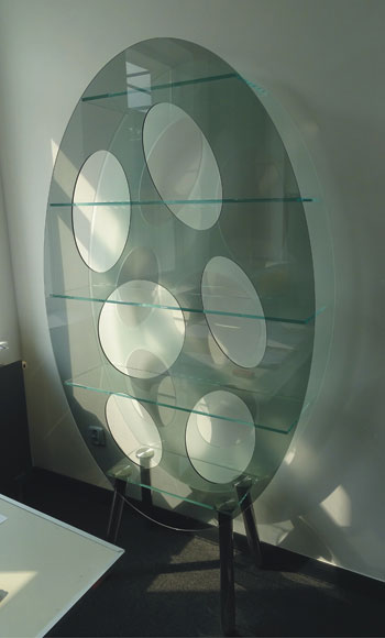
Figure 14.1Example of glass shelf.
Since the company was struggling with short-term planning and they knew about my expertise in this area, they asked me to help them select and implement an appropriate planning software package. As a consultant, I had already engaged in many projects involving Lean and Quick Response Manufacturing (QRM), including several training engagements on these topics. After reviewing the company’s situation, I felt it was an ideal situation where POLCA would be an appropriate solution instead of some complex planning software, and management agreed to explore the implementation of POLCA.
The Factory and Process Flows
Szklo’s factory is located in Lidzbark Warminski, and employs 100 employees in a production area of around 3,000 square meters (about 32,000 sq. ft.). The manufacturing facilities include numerically controlled machines for processes such as cutting, grinding, chamfering, engraving, milling, and drilling. Additional processes include painting, laminating, gluing, screen printing, and hardening. Due to an increase in orders but because of their capacity constraints, the company had turned to traditional efficiency methods such as running larger batch sizes to reduce the occurrence of setups. However, this had resulted in large buffer stocks between operations, longer lead times, and hence more expediting and rush orders, as explained below.
Figure 14.2 provides an overview of the processes in the factory. There are three main types of manufacturing processes: cutting (R1 and R2), machining (NH1 through NH4), and finishing (SH1 through SH4): all these are described in more detail below. As an explanation for the abbreviations for these three areas, R comes from Rozkrój, the Polish word for cutting, NH is from Nowa Hala, the new production hall, while SH is for Stara Hala, the old production hall. The figure illustrates the complexity of the possible flows through the factory, depending on the particulars of each order. Now we describe each of the main processes in detail, as this will be needed to understand many of the problems that the company was experiencing.
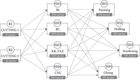
Figure 14.2Complexity of multiple flows through the factory.
The Cutting Operations and Resulting Inventory
The cutting was done by starting with a large pane of glass. Because of the specialized nature of the materials, and their high cost, the emphasis was on optimizing the nesting of parts being cut from one pane. So, the nesting planners looked at a large number of orders to nest parts and minimize wasted glass. The result was a large buffer filled with orders waiting in front of the machine for their turn in the nesting. Next, the supervisor of Cutting would search through this buffer to find orders from future dates that required similar material and setups, and he would execute them all together to minimize changeovers. Also, in order to further optimize the nesting, the planners used a database of frequently ordered products to fill in the nests and build these parts to stock, rather than to particular customer orders. Both these aspects—nesting far in advance, and cutting parts for stock—meant that there was a large amount of work-in-process (WIP) after the Cutting operation.
The next result was that the Cutting operators frequently complained about the lack of free pallets and storage space. Therefore, often, makeshift wooden pallets were prepared to temporarily store the WIP. To make things worse, because of lack of space some of the parts had to be transported outside the factory and stored in the open air. Ironically, although the whole idea of the nesting was to economize on material costs, the multiple movements along with external storage of the parts resulted in quality defects such as abrasions, cracks and scratches, thus creating rework and scrap!
A final issue was that because of the changes that customers were making to orders already in progress, the Cutting supervisor was engaged in frequent changes of schedule and related fire-fighting.
The Machining Department and Sequencing Problems
The Machining department has three linear grinding machines and a group of CNC machines. Again, in attempts to minimize the frequency of changeovers, the Machining supervisor tried to batch together orders that could be machined with minimal changeover times. However, the operators of the grinding machines would complain that the sequences being used in the Cutting department prevented similar types of orders from arriving at their machines, so they would make frequent trips to Cutting to negotiate with its supervisor to get suitable sets of parts that they could run together on their grinding machines.
In addition to this, there were frequent priority changes due to quality problems and scrap (as discussed above), or because of customer specification changes. All these resulted in orders being interrupted and waiting in queue, again adding to the WIP in the factory.
Finishing Processes
The final stages of production involve finishing processes including painting, hardening, screen printing, gluing, or drilling. The highest degree of nervousness in the schedule was experienced in this area. The workers in these finishing processes stated that the arrival of material in this area felt like a big lottery! Some days there was so much material that it was hard to move around the shop floor, yet on other days their machines were waiting for jobs to arrive because of the resequencing at earlier processes. On such days, the supervisors of these areas spent a lot of time visiting upstream processes to find jobs that could be expedited and brought to the Finishing department. Yet, on the days that the finishing processes were busy, they were often working on orders that had been changed by the customer, but the information had not caught up with the jobs on the shop floor!
One more issue that impacted all the departments was that management believed in planning the factory at even more than 100% of available production capacity. This, combined with the various problems mentioned above, meant that a large amount of overtime was needed, with Saturdays and Sundays being used in an attempt to catch up with all the backlogs.
Initial Design of the POLCA System
In 2011, I had the opportunity to educate the management about Quick Response Manufacturing (QRM), along with its production control system, POLCA. Management felt that this would fit their needs and help to resolve their problems, and they proceeded to investigate QRM and POLCA with my assistance.
The first step was for key people in the company to be trained in QRM, which included the concept of cells. Then, prior to moving to the POLCA implementation, they went through the process of checking the prerequisites. One of the next steps was to check the possibility of forming cells before implementing POLCA. However, they soon decided that, because of the large size of the machines, and the fact that each machine was actually handled by two to four operators, in most cases they could treat each machine as a cell.
Initial POLCA Loops, Quantum, and Number of Cards
With this decision as a starting point, the project team decided on all the loops as shown in Figure 14.3. This resulted in a total of 24 loops. For clarity of representation, each arrow in this figure represents a POLCA loop, with the loops R2/NH4 and NH4/SH2 shown in detail, along with their associated cards.

Figure 14.3Initial set of POLCA loops. Each arrow represents a loop. For example, the loops R2/NH4 and NH4/SH2 are shown explicitly.
To decide on the quantum, we first discussed a new material transport method, and designed trolleys that would carry a POLCA card on a hanger (Figure 14.4). Next, based on the amount of parts that could be accommodated on a trolley, we calculated that a quantum of two hours of machine time would be appropriate in most cases to accommodate parts on one trolley. Finally, based on this quantum we used the procedure to calculate the initial number of POLCA cards (see Chapter 5) and arrived at a total of 79 cards in the whole system.
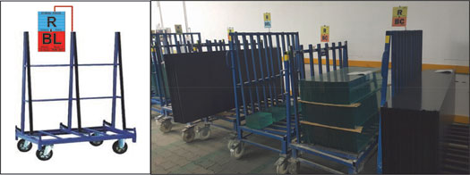
Figure 14.4Design of the transport trolleys with hooks for POLCA cards. The picture on the left shows the concept, and on the right, examples of trolleys in use with various POLCA cards.
We also checked this calculation with the current situation. We observed the WIP in the factory and converted it to the equivalent number of POLCA cards, using the quantum. Interestingly, the current WIP amounted to around 132 cards, showing that the POLCA system had the potential to immediately reduce the WIP by around 40%! Even more interesting, the workers on the shop floor were still complaining that they did not have enough pallets, but at the same time they did not have the right jobs. So, we knew from these initial calculations that we were on the right track with moving to POLCA.
Authorization Method
For the Authorization portion of POLCA, we decided that this would be done by the Cutting supervisor, prior to the first cutting process. This supervisor had access to all accepted orders with calculated process times and based on the shipping date and his experience he would assign the Authorization Date for Cutting. From Cutting onward the system would operate on the Release-and-Flow POLCA rules.
Simplifying the Design: Moving to POLCA “Lite”
After we completed the initial design of the entire system, we explained it to the key managers, production supervisors, and operators. The feedback from the group consisted of two main points. First, people thought the system was too complicated and felt that 24 different loops would be too many to manage. And second, they were concerned about day-to-day variability of the workload across different cells. We had calculated the number of POLCA cards based on average demand for a quarter. However, their experience was that the high variability in mix of jobs could put significantly more short-term load on some machines, and the lack of POLCA cards could starve these machines and/or downstream operations.
Following some brainstorming sessions, the idea that emerged was to combine upstream machines of a given type into a “Sector” that still supplied individual downstream machines, and to have the cards returned from the downstream machines to the Sector Board. This would give a larger pool of cards so that if a given downstream machine had a higher workload, it could draw from this bigger pool of possible jobs.
Drawing from popular terminology, we decided to call this modification “POLCA Lite!” Figure 14.5 uses an example to illustrate the difference between classic POLCA and POLCA Lite. In the classic POLCA, each upstream cell would have an individual loop to all its possible downstream cells. In POLCA Lite, as one example, the cells NH1 through NH4 were combined into Sector NH, and the sector as a whole had a POLCA loop to each of the downstream cells. For example, consider the loop shown to Cell SH2. In a given week, if there was a lot of work for SH2, then all the upstream NH Cells together could use the sector cards to send jobs to SH2.
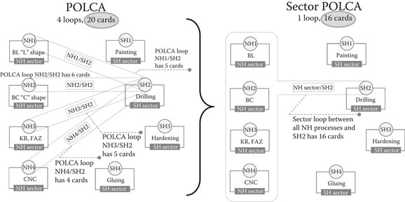
Figure 14.5Illustration of the concept used to simplify the design and create the POLCA Lite system.
In a similar fashion, we combined the Cutting area into one sector (R) and created POLCA loops from Sector R to the NH operations. During this change it was also decided that the NH sector should be separated into six downstream cells. Figure 14.6 shows the POLCA Board used for the Sector R and NH connections with POLCA cards from Sector R to the six NH cells (BC, BL, DEL, CNC, KR, and FAZ).
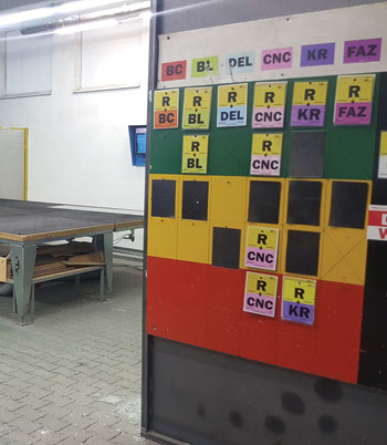
Figure 14.6POLCA Board for Sector R to the six cells in Sector NH. For example, the BL column shows that there are two cards available for jobs going from Sector R to Cell BL.
These design modifications reduced the number of loops from 24 to 10, and the number of POLCA cards from 78 to 54. The simplified POLCA Lite system was approved by the Szklo team and we moved on to the implementation.
Results of the POLCA Implementation
Within just a few months of implementation, the POLCA system was already beginning to show significant results. The following results were observed in less than one year, and have continued to be realized:
The system has stabilized, with an average of 58 POLCA cards in a planning period, which translates to a reduction of 56% from the WIP levels before POLCA—in short, the WIP has been slashed by more than half!
The reduction in WIP also means that the company no longer has to store parts outside the factory, thus also reducing problems with damage and quality issues.
The large reduction in the number of pallets allowed the company to justify investing in specialized trolleys (as shown in Figure 14.4). The customized design of the trolleys combined with the limit imposed by the quantum has meant a reduction in damage due to lifting and setting down of parts, and also due to the previous moving back and forth of pallets.
The reduction of WIP by more than 50% has also translated into a reduction of production lead time by more than 50%. This has also meant that orders are released later to the shop floor, and there is more time for customers to make changes before the job is actually started.
The shorter lead time also means that they don’t need to plan as far ahead and so there are fewer hot jobs and fewer schedule changes.
There is less of a concern about machines not having any work to do. POLCA keeps the jobs flowing without creating excessive WIP. The logic in the POLCA system makes sure that jobs get to machines in time when it is necessary, and if a machine has no work at a given moment, people now trust that it is okay with the current conditions, and they don’t run around trying to find work. The visualization in the POLCA system also helps workers and production leaders understand and trust the system in such situations.
As a result of the previous two points, production leaders now spend very little time on chasing upstream jobs or re-scheduling their areas, and they have more time for coaching and improvement of the processes.
With all the above factors, the company’s on-time delivery performance has improved by 30%.
As has been the case with other POLCA implementations, Szklo also experienced benefits with the buy-in from the people on the shop floor. In the words of the production manager, compared with the past situation where supervisors and managers were involved with expediting jobs, “The POLCA system has now involved our front-line operators to take responsibility for the flow of materials.”
About the Author
Karol Bąk graduated from the Technical University of Gdansk with a Master of Science degree in Management and Production Engineering, and began his career in industry as a manufacturing and supply chain manager. Since 2012, he has worked as a consultant with 4Results, Warsaw, and been involved in over ten QRM implementations. He is one of the pioneers of QRM in Poland, and the author of several technical papers and training materials related to QRM and POLCA. He also works as a lecturer on QRMrelated subjects at the Technical University of Gdansk.