
12From the Netherlands: Creating Flow and Improving Delivery Performance at a Custom Hinge Manufacturer through QRM and POLCA
Guest Authors: Godfried Kaanen and Robert Peters
SECTION I: THE JOURNEY TO POLCA, by Godfried Kaanen
BOSCH Hinges is a high-mix, low-volume manufacturer of custom-engineered hinges (bespoke hinges) in steel and stainless steel. The company specializes in small orders ranging from a single prototype to 2,500 pieces. BOSCH Hinges serves customers in many industries, including equipment manufacturers, land transportation (both rail and vehicle industries), aviation, and the maritime sector. Short delivery times and a very high delivery reliability are key attributes of the company. As the owner of BOSCH Hinges, in Section I of this chapter I will lead you through my personal journey to POLCA.
I Get a Rude Wake-Up Call
In 2004, we had started to embrace the concepts of Lean and were determined to succeed on a never-ending journey of continuous improvements. The battle against high volumes, low prices, and competition from low-cost countries left us only one opening: strive for maximum productivity of our staff and seek the niche position of high-mix, low-volume and custom (HMLVC) producer. Serving our clients with the best quality hinges, engineered and produced in short lead times and in exact quantities, however small, became our goal. It seemed that we had hit upon the right strategy. Customers were glad that we accepted smaller orders without negotiating for larger quantities, and they were satisfied with the quality of our products. Our performance as a company seemed to be improving, both in the eyes of our customers as well as in our financials, and we felt we were on a good course. But then in the winter of 2006, I received a loud and unexpected wake-up call.
I had an annual meeting with the purchasing department of an important German customer in the rail sector, an international corporation that we supplied almost every week. Even though the orders came weekly, they were widely different, with each order consisting of numerous types of hinges in varying quantities, and with options specific for this customer. During the meeting, which involved three purchasing managers from the customer, I felt like I was being waterboarded. Although we had been supplying this customer for more than 15 years, nothing seemed to be right in their eyes: our delivery times were poor and our delivery reliability even worse. Thanks to our quality, which was never an issue, we didn’t completely fail their criteria, but their overall vendor rating report for us was nothing to be proud of: they gave us a “C” grade. In summary, their decree to me was: “Cut your delivery times from four weeks to two, and improve your reliability to above 95% on-time.” They also warned me that if our overall grade did not improve to an “A” within 12 months our position as vendor would be at risk.
With that load on my shoulders, I drove 160 miles back to my company. On the way back, I had time to reflect on how we had arrived at this point.
Our Initial Improvement Efforts
We started our efforts in 2004 by taking courses in Lean and also arranging for in-house training from a consulting company. Applying toolbox elements of Lean led to improved productivity. We reduced stocks of raw materials to a strategic minimum. We stopped making finished goods to stock, and started making only to specific customer orders. We eliminated in-between stocks of semi-finished goods, and greatly reduced our work-in-process (WIP). Times for equipment setup and tooling changeovers were shortened. Lead times started going down.
It seemed that we were on the right path. But even as we continued down this path, customers kept pressuring us for ever-shorter and more reliable delivery times. This was also starting to take its toll on our staff. When we first started our Lean efforts, our employees were enthusiastic. However, they were also hesitant to change and, especially as we felt more pressure from the market and tried to keep up, the continuous changes felt like a burden for many of the employees. In evaluating the situation, I realized that we were struggling with two major issues: our poor performance on delivery reliability, and the expertise of our staff.
The Pastry Shop Needs a Breakthrough
For a better understanding of these points, let me explain our situation at the time. Every year we released around 1,600 production orders onto our shop floor, and these orders covered over 400 individual designs. And to make things more difficult, order sizes ranged from a single prototype hinge to 2,500 pieces.
The choice of materials that we work with is also large: mild plain steel in two grades, stainless steel in grades 304 and 316, pre-galvanized steel, and Zincor. Material thicknesses range from 0.8 to 5 mm. In total, we stock more than 50 items as raw material in sheet metal. The number of manufacturing operations needed to produce a custom-engineered rolled hinge is also large: laser cutting or die-nibbling of male and female cut-out flat parts, pre-rolling, rolling, calibrating, axial and radial corrections, bending, folding, countersinking, threading, galvanizing, powder coating, production of the pin, assembly, packing, and shipping. Even before all these, you have to add the processes of design engineering, manufacturing engineering, and routing preparation for every order. Every hinge we produce is a customized mix of the above (see Figure 12.1 for examples). With all this to be done, you can see that having a staff of just 25 people on the shop floor plus some temporary workers put a great strain on the required skills of the employees.

Figure 12.1Examples of custom hinges.
This is how complex a small job shop operation can be. We are a classic example of HMLVC production. I often compare our company with a gourmet pastry shop: an enormous variety, every item freshly baked in small batches, and everything must be ready every day just in time for the demanding customers!
In reflecting on our journey, it became clear to me that, despite our Lean efforts, production planning and control were still troublesome: too much to plan, too many details to take care of, and too much dependency on the skills of our individual employees. So even though our company had become leaner, we still faced the phantom of late deliveries. And it wasn’t going to get any easier. The pressure from our customers for even shorter delivery times was growing.
As I drove those 160 miles back home, I realized that fine-tuning our Lean efforts wasn’t going to do it: we needed a breakthrough!
Thus it was that, in the spring of 2007, I decided to initiate a whole new and major improvement project, which we called “Getting a grip on production planning.” The keys that we were looking for in this project were how to preserve operational flexibility while maintaining reliable delivery, and how to cope with all this in our HMLVC production environment without stress for our employees.
Our First Step: The Rhineland Model
We have always been inspired by theoretical models, so we started researching possible approaches, and found one that seemed suited to our situation. It was the Rhineland model described by Jaap Peters and Mathieu Weggeman in The Rhineland Way (Business Contact, 2013). Two elements particularly interested us—a cell-based structure and greater employee responsibility—because these could potentially address both our challenges.
To determine a cell-based structure, we analyzed the routings for four months of production orders—around 600 orders in total. We identified every single operation for each production order and marked it in an enormous spreadsheet, ending up with a spreadsheet that was 600 lines deep and 50 columns wide—no wonder that we had constant planning problems! Using this data, we defined cells as clusters of coherent operations and gave each cell a name. This led us to identify nine work cells on the shop floor. Drawing the cells in a factory layout on paper gave us an immediate overview. We realized that the planner was not to blame for orders being late without this overview.
We also realized that our staff had been assigned highly diverse individual jobs. In our existing process, an employee had to manage an individual job from end to end. It appeared much too complicated for the less-skilled employees. Not everyone knew the characteristics of each equipment and mistakes were made in setting up the tooling. Worst of all, employees would bump into each other at their next production step, creating queues and low productivity. Orders ending up being late, and as employees couldn’t do much about this, morale was low. Instead, we felt that assigning employees to a particular cell (their “home” position) would limit the variety of the work to be done by each of them, but would raise the quality of their work.
Next, we created a buffer zone for every cell: an identified space where WIP that needed to be handled at that cell was to be placed. (To this day, when I visit companies I see few examples of shop floors where clear areas are defined for placement of WIP during the production process.)
As we moved forward with these ideas, we found that creating nine cells on the shop floor provided a good overview for the production manager and planner but it still did not control the production flow. The consultant helping with our Lean implementation had told us that you need to pull orders rather than push them. We had learned about Kanban and the Pull system. But with our diverse and customized orders, we didn’t see how to apply this system.
At this point, we were trying to solve a puzzle that involved several issues:
How do we prevent our upstream cells from pushing work to the downstream cells and creating an overflow of WIP in the buffers?
How do our upstream cells know specifically what to make at a given moment to supply the right items needed by the downstream cells?
How do we quickly communicate and deal with day-to-day capacity limitations of cells due to unanticipated issues, such as jobs that take longer than expected, employee sick leave, last-minute holiday requests, and breakdown of equipment or tooling?
In short, even after the cells were in place, we needed some form of shop floor control, but it had to build on the cellular structure we had created.
We Are Introduced to POLCA
The answer to our puzzle came from a junior consultant, Jacob Pieffers of the consulting firm, who along with his advisor Professor Jan Riezebos had written a masters thesis, “POLCA als innovatief materiaal-beheersingssysteem” (POLCA as an innovative material control system) (University of Groningen, the Netherlands, 2006). For his thesis, he had taken a course at the Center for Quick Response Manufacturing (QRM) at the University of Wisconsin–Madison. Jacob explained the concepts of QRM to us, and also POLCA as a control mechanism as part of QRM, specifically designed for the control and communication between cells. There was instant recognition for us that this applied to our situation. Jacob showed us Rajan Suri’s book, Quick Response Manufacturing (Productivity Press, 1998). I immediately ordered the book.
By this time, it was the summer of 2007. My wife and I had rented a cottage in Rügen, a beautiful island in northeast Germany. Rügen is the German version of Cape Cod. In the 1920s and 1930s it was a resort for rich industrialists of the time. Later, from the 1960s to the 1980s, leaders of the communist party of East Germany would spend their holidays here, hidden away from their people. I was really intrigued by Suri’s book, and decided to spend the holiday reading the book. But there is a lot to see in Rügen, so I had to negotiate a deal with my wife, who stated categorically: “In the morning you can read your book, then in the afternoon we will cycle around the island, and in the evening you will take me to a restaurant of my choice.” I didn’t dare refuse! So, every morning I read some more of the book. Chapter after chapter hit home with me; I felt as though “this book is about my company!”
In particular, POLCA as a shop floor balancing and control mechanism to complement the cells fitted in perfectly with our company’s needs. My decision to go for POLCA was made.
Next came the implementation phase, which took a few months. I realized that we needed to do several things to improve the cellular structure based on QRM thinking, and to create the foundation for POLCA, so I decided to engage the consulting firm for a second assignment. With their help and revived enthusiasm of our own staff we rearranged the shop floor to create an improved layout for the defined cells. We placed the cells as much as possible in a horseshoe layout based on overall flow patterns, and gave each cell a name based on a color (Figure 12.2). We created clearly marked buffer zones for every cell for WIP to be placed. This first set of tasks was completed between August and December 2007.
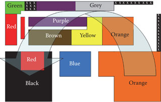
Figure 12.2Improved cell layout with defined colors and overall horseshoe flow.
Next, we designed the POLCA cards and boards, and a board was placed in each buffer zone. Production order sheets needed to be revised for each order to specify the cell sequence. This workflow had to be specified in our ERP system. It was a period of three very intense months.
We weren’t worried about achieving perfection. We felt like eager Boy Scouts on an adventure and moved rapidly along! Obviously, mistakes will be made in such a situation, but we were ready to adjust in real-time. The first POLCA board is an example. After Rajan Suri visited us in 2008 and made some suggestions, we quickly made a second version (see both versions in Figure 12.3). This happened several times with many of our choices.
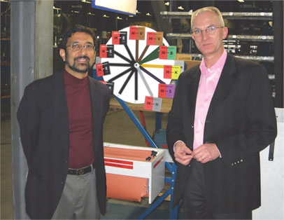
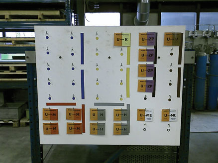
Figure 12.3Examples of POLCA Boards. The first attempt is on the left, pictured with Rajan Suri and Godfried Kaanen. The improved board after Suri’s feedback is on the right.
We felt that our staff needed training in the details of POLCA and how the system would work. Our operators are used to “hands-on” work and we felt that a physical simulation would be better than an overview of the theory. Such a simulation didn’t exist so we had it developed by the consulting firm. We were so determined that the principles of QRM and POLCA as job shop control system were right for our situation that every expense was taken. The consultants developed a POLCA Game, which included a physical simulation (see Appendix F). We used this game to train our staff on working with POLCA.
Implementing the Color-Coded Visual System
Our next step was creating a visual system for communicating the order flow to the shop floor people. Each job has to follow a specific routing related to the customer order. At first, we glued the cell sequence on each order sheet with colored stickers (Figure 12.4). For over a year our production manager spent up to two hours every day reading order details and gluing stickers in the right sequence on every order sheet. A boring and repetitive job! But knowing the value of the visual signals to the workers kept him going.

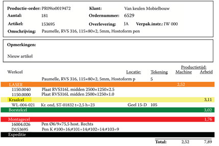
Figure 12.4Putting Visual Signals into the Routing Sheets. The left side shows how we started by attaching colored stickers. Then we worked with our ERP vendor to incorporate the colors in the routing printouts, as shown on the right side.
It was clear that this was exactly the kind of job that should be automated using information technology. So, we asked our ERP vendor if they could print the colors on the order sheets along with the routings. Their answer was that that it couldn’t be done! “Do you realize what that means in terms of programming work?” they said. “And what it will cost you in terms of the number of full-color pages printed in a year?” To which we replied, “Yes, we realize it very well, and we are determined to buy a color printer that can handle this volume of printing. Whatever the cost, the printer will pay back very soon. We will save so much time of the production manager attaching stickers every day. And do you realize the value of visual communication? Our employees need the visual cues to attach the right POLCA card to the right job. If you make this improvement in your system, you will see that other companies will follow.” The discussion felt like David against Goliath, but we won (see Figure 12.4). The add-on to our ERP system paid back soon and kept paying back. We couldn’t have maintained our POLCA operations without it.
We kept the POLCA cards simple, as specified in the theory, with the two cell colors and abbreviations of the cell names, and we also added an arrow to clarify the direction of flow (Figure 12.5). In the figure, you will notice that although the POLCA principles recommend putting serial numbers on the cards, we decided we didn’t need them. We had a small factory and the production manager would periodically check on the total number of cards. The initial number of cards per loop was calculated by the consulting team. We soon found that, in practice, we could improve on these numbers by making judgment calls from observing the WIP as occupancies changed during the year, and thus tighten up the system. In fact, we started with 90 cards and this was reduced to around 65 cards.
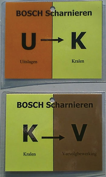
Figure 12.5Examples of the first POLCA cards.
Initial Results from POLCA
With the introduction of cells and POLCA, the whole role of planning changed: the entire job of actively planning orders in detailed steps by our planner disappeared. He got a different job within the company. Planning became a part-time responsibility of our production manager, who released the orders for the shop floor. Let’s remember that the A of POLCA stands for Authorization. When we planned our POLCA implementation, we had decided on the “Release-and-Flow” option or RF-POLCA (see Chapter 5), and thus for each job we only needed the Authorization Date for the release of that job to the shop floor. (We later upgraded our system to the standard POLCA; see the second section of this chapter.) As mentioned, we gave the responsibility of setting this Authorization Date to the production manager, who functioned as the Planning Cell described in Chapter 5. He would sort the orders based on due date and then for each job, based on his experience and the estimated total touch time, he would back-schedule the job from its due date and set the Authorization Date of when to release the job to the first cell in its routing.
In keeping with the RF-POLCA rules, once a job was released, Authorization Dates were not needed for subsequent operations. Instead, each cell had a basket to keep the orders in sequence. As orders arrived at cells, their production orders were arranged in the cell’s basket based on a FIFO (first-in first-out) sequence, as required by the RF-POLCA rules. (The only person allowed to change the sequence for any cell was the production manager.) So, when a cell team had capacity to launch the next job into its cell, it would look in this basket for the next job in the FIFO sequence, check the color of its destination cell, and with the visual aid of the colored sticker, it would look to see if the right POLCA card was available to launch the job.
After we made the initial changes of creating the cells and implementing POLCA we saw rapid improvements. Before POLCA, our lead times ranged as high as six weeks and we could sometimes be an additional two weeks late in delivering beyond that. Without putting pressure on employees, our lead times dropped to around four weeks in the first year, along with high reliability of delivery. At the time of writing this chapter, the lead times have been further reduced to two to three weeks, with very high reliability. With our employees working in teams in the cells, we saw that their productivity rose immediately. This resulted in less overtime and temporary workers. Equally important, fellowship and communication between the cells has created a team spirit and made a tremendous difference.
At this stage, perhaps you are thinking, “What about the German customer you talked about at the beginning?” Oh yes, they are still there. Our relationship is better than ever. We did indeed cut our delivery times to two weeks, and for over six years we have received an A+ vendor rating.
SECTION II: FROM PHYSICAL POLCA TO DIGITAL POLCA, by Robert Peters
After the POLCA system had been operating for over a year, we observed where our employees were spending time on repetitive tasks, and decided to evolve to a more automated system while still keeping to the POLCA principles. In reviewing the activities of the production manager, one of the first priorities for automation was to create a daily Authorization List. We created a computer program to do the back-scheduling based on the routing and estimated lead times at cells, and thus calculate the Authorization Date for each job. With this list created automatically each day, the production manager didn’t need to spend time on the piles of order sheets. This was the first step in what later became the PROPOS shop floor control system described in the rest of this chapter. This also meant that the production manager could spend more time in dealing with strategic improvements and occasionally making minor adjustments if urgent customer orders were received or other unexpected events occurred.
Shortly thereafter, the idea arose to provide each cell with a screen that showed the current situation at each cell based on the routing of each order. Figure 12.6 shows an example of a screen at the Welding Cell. Each line on this screen represents a production order, and the screen is separated into three sections: the “In process” section shows orders that have already been launched and are in process in the cell; the “In buffer” section displays orders that have arrived in the cell’s buffer and have not yet been launched; and the “Expected” section displays orders that have been released to the shop floor and are on their way to this cell, but have not yet arrived in the buffer. This last section allows the cell team to anticipate which jobs might arrive soon and helps them plan their capacity and workload in the near term.
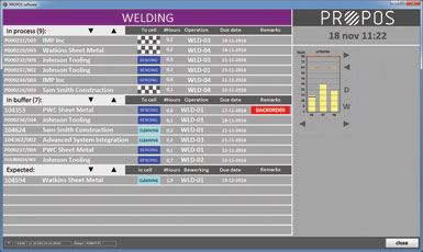
Figure 12.6Example of a PROPOS screen at the Welding Cell showing the status of orders in or destined for the cell.
In this first stage of implementation the PROPOS screens supported the initial order release as well as the sequence at each cell, and we were able to eliminate the FIFO baskets at the cells. Further, the sequence at each cell was now based on back-scheduling from the order due date, and thus we upgraded from RF-POLCA to the standard POLCA with Authorization Dates now being used at each cell. Finally, to support our QRM strategy, the PROPOS system also included the measurement of MCT, including the breakdown into white space and gray space (see Appendix A for more details on MCT and white/gray space).
By the summer of 2010, we had a situation where the PROPOS system specified the work for the cells on the shop floor, but there was also the POLCA system giving people additional information. We realized that people had to look at two different systems (Figure 12.7). First, they had to look at the PROPOS screen for the first Authorized production order (the top line in the “In buffer” section of the screen) and note the downstream cell for that order. Next, they had to check their POLCA board to see if a POLCA card was available for that POLCA loop. If so, they would launch the order in PROPOS and remove the corresponding POLCA card from the board and place it with the material. If no POLCA card was available, they had to look at the next Authorized order on the PROPOS screen and check if a POLCA card was available for that order. And so on.
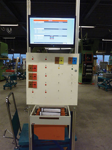
Figure 12.7When the PROPOS screens were first implemented, the cells still used physical POLCA cards. Here we see a PROPOS screen at a cell, as well as the cards on the cell’s POLCA board.
So, although the systems complemented each other and were easy to use, we thought we could make things easier for the people in the cells by unifying the two into one digital system. In addition, there were two practical issues that would be solved by designing a unified system. The first practical issue that we ran into was that a lot of POLCA cards were flowing between a few pairs of cells that were not in the same building. As a result, people had to walk a lot (sometimes through the rain) to return the POLCA cards, causing people to hold back the free POLCA cards and return all of them once a day, which both delayed the POLCA signals for the upstream cells and created lumpy demand for those cells when a batch of cards was returned. The second practical issue was that sometimes POLCA cards got lost so they needed to be counted and replaced regularly. Counting, re-creating and replacing physical POLCA cards in a busy production environment asks for a lot of discipline. When in the course of 2012 the QRM cells Brown and Yellow were merged and when, at the same time, new cells were created—things that happen in a dynamic company—it took some effort to recalculate and create the new cards for the new routes. We felt that all this could be solved by incorporating a digital version of POLCA into the existing PROPOS system.
In early 2012, we started the development of Digital POLCA. The PROPOS system already contained information about all the production orders and their routings. Based on that data, we let PROPOS automatically identify all occurring POLCA loops in the factory. Next, for each POLCA loop, the number of POLCA cards was calculated using the standard formula (Chapter 5). By the summer of 2012 we had implemented the Digital POLCA system throughout the shop floor and people were working with an integrated system for both the production order information and POLCA signals.
Figure 12.8 shows an example of the first Digital POLCA window that we added to the PROPOS screens. This electronic display replaced the physical POLCA board. The figure shows the Digital POLCA board for the cell Yellow. There are seven POLCA loops from the Yellow cell to downstream cells, and you can see the electronic images for the corresponding seven POLCA cards. Next to each image you see the number of cards of that type that are currently available. For instance, for the Yellow/Blue loop, there are four unused POLCA cards at this moment. When the cell team launches a job using the PROPOS screens, the Digital POLCA system automatically reduces the number of cards by one (for the type of card used by the job).
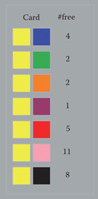
Figure 12.8Example of the first Digital POLCA window added to the PROPOS screens. This is the electronic version of the POLCA board at cell Yellow. It shows the POLCA cards to seven destination cells, along with the number of cards available for each destination.
On the PROPOS screen, the line listing a production order also contains a traffic light symbol (Figure 12.9). If no cards are available for a particular POLCA route, the PROPOS screen displays a red traffic light for all orders with that route. It also blocks those production orders from being accidentally launched. So, the cell team will only be allowed to launch the first production order without a red traffic light.
Figure 12.9This is a line in the PROPOS screen for a production order going from cell Yellow to cell Blue. The traffic light on the right is red, indicating that there are no Yellow/Blue POLCA cards available and the order is blocked at this moment.
One more feature that we added to the digital system was the ability to include temporary POLCA cards along the lines of the Safety Cards and Bullet Cards described in Chapter 6. In some unusual circumstances, as described in that chapter, management may decide to add a few extra POLCA cards. In that case, there had to be a system to ensure that these cards were taken out at some later time. PROPOS takes care of this automatically. You can add temporary POLCA cards for a certain POLCA loop and at the same time provide an expiration date, after which the cards automatically disappear from the loop.
Implementing the Quantum through Load-Based POLCA
News of our first Digital POLCA implementation and its success quickly spread through our region, and we received inquiries from several companies that wanted to implement this system. As we rolled out the PROPOS system at other companies and gained more experience, we added a Load-Based POLCA option to PROPOS in 2013. This option electronically implements the idea of the quantum discussed in Chapter 5, and is ideal for situations where there is a large variation in workload between production orders. If you choose to implement the Load-Based POLCA option, then instead of a production order using one POLCA card, it now uses “x” cards, where x is the workload in hours for this job at the downstream cell. Also, x does not need to be an integer, as required with physical cards; it can be any number, including fractions.
We can explain the implementation using the PROPOS screen shown in Figure 12.10 for the Welding cell. Looking at the “In buffer” section (see the enlarged portion in the lower half of the figure), the first Authorized order is blocked by the system, as shown by the Red traffic light on that line. The reason is, it needs 0.6 POLCA cards of type Purple/Blue, but from the 45 cards in the system, there are currently none available. The second order is also going to Blue, so it too is blocked for now. So, if the cell team has capacity, the system will allow it to launch the third order, which is destined for Light Blue. This one needs 0.2 cards of type Purple/Light Blue, which is possible because there are 38 available.
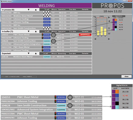
Figure 12.10Upper picture shows a PROPOS screen for the Load-Based POLCA option. Lower picture enlarges the “In buffer” portion of the screen so you can see the number of POLCA cards needed and the resulting red lights.
The preceding discussion highlights one more advantage of an automated system: it would be difficult and time-consuming for people to calculate and manage Load-Based POLCA at this fine level of detail. Along the same lines, the automated system has enabled us to add specific features requested by customers based on their unique situation. In one case, we added some additional logic to help reduce the idle time at highly constrained resources; this is described in the Provan case study in Chapter 13. In another situation, we added flexible POLCA cards where the system can move cards between upstream loops that are all destined for the same downstream cell. The total number of cards for the downstream cell remains the same, thus still constraining WIP and congestion, but the cards get moved between loops when demand varies a lot at the upstream cells. In all such modifications, our aim has still been to keep to the main goals of POLCA and also aim for simplicity, not making the computerized system too complex, and thus retaining the buy-in from the shop floor people.
Impact of PROPOS and POLCA on the Company’s Operations
As can be expected from any computer-based system, it is easy to look up the status of orders at any time to see where they are in the shop. The difference with PROPOS, incorporating the POLCA logic and operating rules, is that the shop floor performance is very reliable, and management can have confidence in meeting the due dates in the system. Godfried Kaanen (first author) had a recent personal experience with this. He was just about to leave at the end of the day before the Easter holiday weekend, when the phone rang. He picked it up and it was an important customer wanting to be sure his order would arrive on time the following week. In the past, Godfried would have had to walk into the factory, try to find the order, or maybe even chase down his production manager who had already left for the holiday. Next, he would have had to check how many steps the order still had to go through and estimate if the order would be ready on time. With PROPOS, Godfried could immediately see which step the order was in, that the system predicted it would be shipped on Tuesday, and that the customer would receive it on Thursday, as promised. Godfried could confidently answer the customer, knowing that due date performance is now very reliable.
Beyond some of these functional enhancements from the system, there have been broader impacts on the organization as a whole. Prior to implementing the full functionality in PROPOS, there was a lot of staff time involved in planning and scheduling. As explained earlier in the chapter, the company had a full-time planner, plus the production manager spent a lot of time calculating release dates. In addition, if customers changed delivery dates for orders already on the shop floor, the production manager had to manually reprioritize the orders in various FIFO baskets at the cells. And finally, the managers had to keep an eye on the progress of jobs to detect any jobs that were in danger of being late.
With the POLCA logic incorporated in the PROPOS system, combined with the other functionalities described above, several benefits have been realized. First, the planner’s job was no longer needed and he could be productively employed in another capacity. Adding the equivalent of one person’s capacity is quite significant for a small company! Second, changes in customer request dates get automatically reflected in the revised Authorization Dates in the PROPOS screens, and this along with the POLCA rules helps to keep jobs on track. And third, the PROPOS screens clearly highlight jobs that are behind schedule (if they should have been launched already, but are not yet in the cell) so shop floor personnel can see if they need to take some corrective action, without requiring a manager to constantly be on top of this situation. The shop floor workers also like having the information clearly on the screen. In the past, they would often check with the production manager before starting a job, just in case something else had come up. Now they can see clearly what they need to do and don’t have to wait for a second opinion and reassurance. All these preceding points have given the workers a higher feeling of ownership and pride in their jobs. Equally important is that the production manager, instead of spending time on day-to-day micromanagement, can now spend much more time on strategic improvements with cumulating benefits for the company.
As a final conclusion for both sections of this chapter, at BOSCH Hinges we have seen significant quantitative as well as qualitative benefits from the combination of the POLCA system rules and the PROPOS digital system’s implementation features.
About the Author
Godfried Kaanen is an entrepreneur in the SME (small- and medium-sized enterprises) metal industry in the Netherlands. He believes that the industry and in particular SMEs are an indispensable pillar to any economy. His motive is the pursuit of operational excellence. He combines his private business at BOSCH Hinges with the chairmanship of Koninklijke Metaalunie, the Dutch employers’ organization for SMEs in the metal industry. The more than 13,000 affiliated members employ approximately 150,000 people and jointly represent a turnover of more than 22 billion Euros. Godfried is also known as one of the ambassadors for QRM (Quick Response Manufacturing) in Europe.
Robert Peters is co-owner of PROPOS software. He has over 18 years of experience in business (sales, marketing, and project management in different sectors) and over 12 years of experience in developing and implementing software solutions at innovative companies to help them improve their results. Robert has a B.ICT degree from the HAN University of Applied Sciences in Arnhem, the Netherlands.