
CHAPTER 8
Modeling Interactions in UML 1.4
![]()
- Modeling behavior with UML 1.4 and UML 2.0
- Modeling object lifelines
- Modeling messages
- Mapping messages to operations
- Modeling various types of messages
- Modeling iteration and recursion
- Modeling object creation and termination
- Modeling object activation and focus of control
- Modeling the Collaboration diagram
- Evaluating the difference between the Sequence and Collaboration diagrams
- Integrating the Sequence and Collaboration diagrams with the Class diagram
![]()
In Chapter 3, I provided an overview of the UML diagrams. I distinguished their use around three general headings: structural diagrams, behavioral diagrams, and model management diagrams. The structural diagrams (class, object, component, and so forth) represent how the objects are defined and how they are related to one another. They do not represent how the objects behave when you put them to work. In contrast, the behavioral diagrams represent how the objects work using the structure already defined in the other diagrams. This dynamic view contains diagrams specifically designed to model how the objects communicate in order to accomplish tasks within the operation of the system. They can represent how the system responds to actions from the users, how it maintains internal integrity, how data is moved from storage to a user view, how objects are created and manipulated, and much more.
Because system behaviors can be large and complex, the behavioral diagrams tend to look at small, discrete pieces of the system such as individual scenarios or operations. You might not see the behavioral diagrams used for all system behaviors simply because not all behaviors are complex enough to warrant a visual explanation of the communication required to accomplish them. Even so, the Class diagram and the various behavioral diagrams are the most often-used diagrams because they most directly reveal the specific features required to generate code.
Table 8-1 shows the three behavioral diagrams in UML 1.4 (Sequence, Collaboration, and Statechart) compared to UML 2.0's five. UML 2.0 renames two diagrams and adds the Timing diagram and the Interaction Overview diagram.
Table 8-1 Comparison of Behavioral Diagrams Between UML 1.4 and UML 2.0

This chapter covers the Sequence and Collaboration diagrams of the UML 1.4 specification. Chapter 9 discusses the UML 2.0 Sequence, Communication, Interaction Overview diagrams, and Timing diagrams. Chapter 10 explains the UML 1.4 Statechart diagram. Chapter 11 explains the UML 2.0 State Machine.
Modeling a Sequence Diagram
The Sequence and Collaboration diagrams are most often used to illustrate interactions between objects. As such, they both model objects and messages between objects.
 The diagrams can also be used to model interactions between classifiers, as is done to model the interactions for a collaboration.
The Sequence diagram uses a time-oriented visualization. It uses a set of object icons and associated timelines, together called an object lifeline, for each object. In contrast, the Collaboration diagram presents a structure-oriented visualization. In fact, the Collaboration diagram's notation is based on the Object diagram notation that models objects and links.
 You might think it's odd that the UML has two diagrams that do the same thing. In a way, you're right. The reason is that they come from different methodologies and each offers a slightly different perspective that can be quite valuable. The two diagrams are compared later in this chapter.
The common feature of both diagrams is the ability to represent interactions. Interactions show us how objects send messages to each other. When one object wants to send a message to another object, the second object has to have a way to receive the message. The message must match an interface provided by the second object. It is kind of like receiving a phone call. The person receiving the call has to own the number being called in order to receive the call. The number is the interface. So interactions, messages sent between objects, reveal interface requirements. The interface is literally an operation.
 See Chapter 5 for an explanation of operations.
This pairing of messages and interfaces is helpful in two ways for building and testing your model:
- It can point to existing model elements. If one object needs to send a message to a target object, you should check to see if the second object already provides the needed interface. When using a modeling tool, this is as simple as pulling up a list of the defined interfaces for the target object and then picking the matching interface to complete the interaction. In a modeling tool, you might accomplish this either by accessing the list from within the Sequence or Collaboration diagram, or by checking the object's corresponding class specification in the Class diagram. This ability to choose existing interfaces makes adding new features to a system very quick and easy, which can, in turn, facilitate the development work in subsequent project phases and later maintenance activities.
- It can aid in discovering the need for new model elements. If you find that you need to send a message to a target object, but that object does not have a corresponding interface, then you have discovered a new interface requirement. Similarly, if you do not already have an appropriate target object to take responsibility for receiving and responding to the message, then you have discovered a requirement for a new type of object, a new class definition.
Figure 8-1 shows a clip from the MagicDraw Sequence diagram menu for an event object. Note the two options in the bottom right corner, <new operation> and Call Action. While the actual labels may differ between tools, the same two concepts are commonly supported. The Call Action is an example of approach 1; it provides the list displayed on the left side of the figure containing all the operations already defined on the event class. The <new operation> option is an example of approach 2; it enables you to define a new operation (big surprise). The new operation is added to the specification for the class that the current object belongs to, that is, the Event class.
Sequence and Collaboration diagrams are based entirely on messaging requirements. Messaging requirements come from the fact that objects are required to perform behaviors. So where do you find the behaviors you need to model? In many projects the use cases are created first because they model the behaviors of the system expected by the clients. These behaviors provide the basis for building scenarios. Each scenario describes in text form how the system should behave under a specific set of circumstances, such as using the system to select a show to attend. The Sequence and Collaboration diagrams provide a pathway from the textual descriptions of behaviors in the scenarios to the operations/interfaces required by the Class diagram in order to generate code.

Figure 8-1: An example of the automated support for finding operations, and for adding new operations based on messaging requirements.
©No Magic
The scenarios also provide a basis for developing test cases and an acceptance-level test plan. Chapter 12 explains use cases and scenarios.
Modeling an object lifeline
While classes define the types of behaviors that objects can perform, all behavior in the object-oriented system is performed by objects, not classes. Objects take on the responsibility for editing data, storing data, moving data around in the system, responding to queries, protecting the system, and more. Objects work together to perform these tasks by communicating with one another. Examining how specific objects work under specific circumstances reveals the exact nature of the communication.
Consequently, Sequence (and Collaboration) diagrams are most often modeled at the object level rather than the class level. This approach also supports scenarios in which multiple objects of the same class work together as, for example, when one employee object collaborates with another employee object. It also allows the Sequence diagram to model facts in the forms of concrete test data and examples, instead of more general concepts or rules captured in the class specifications. The Sequence diagram uses two fundamental notation elements: object lifelines and messages or stimuli.
The object lifeline notation combines the object icon notation and a timeline. The object notation is the same icon used in the Object diagram in Chapter 7: a rectangle containing the object name. In this example, I use the common anonymous object notation :classname. Figure 8-2 drafts a scenario in which a customer selects seats to purchase at a performance in the theater. You see the five participating objects lined up across the top of the diagram. The top of the diagram is the default location for all objects in a Sequence diagram. Positioning an object at the top of the diagram indicates that the object already exists at the outset of the scenario. This implies that positioning an object lower in the diagram models the creation of the object during the scenario.
The object lifeline includes the rectangular object icon and the vertical dashed line below each object. The line is a timeline that runs from the beginning of a scenario at the top of the diagram, to the end of the scenario at the bottom of the diagram. The amount of time represented by the timeline depends on the length of the interaction you are modeling.
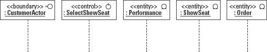
Figure 8-2: Object lifelines for five objects.
Note that an object lifeline, that is, an object icon and its associated timeline, may actually represent a set of objects such as an application, a pattern, a subsystem, or simply a collection of objects of the same type. This high-level view can sometimes help you work out the “big picture” behavior before digging deeper to work out the details. For example, the SelectShowSeat object in Figure 8-2 represents a collection of objects that together manage the behavior of the application. The ShowSeat object represents all of the ShowSeats in the application.
Modeling a message or stimulus
A message is the formal specification of a stimulus. A message is a definition of some type of communication between objects. As such it may invoke an operation, raise a signal, or cause the creation or destruction of the target object. A stimulus is an instance of a message. The message explains the roles of the sender and the receiver of the stimulus, as well as the procedure that generates the stimulus. For practical purposes, we can think of a message and a stimulus as the same thing, that is, as a unit of communication between objects, so I will use the term message in the rest of this book. (Details about the distinctions between messages and stimuli are provided in the “Stimulus, message, operation, and signal” section later in this chapter.)
A message is modeled as an arrow. The type of arrow visually describes the type of message. Perhaps the most common type of arrow is a solid line with a solid arrowhead, representing a message that requires a response, called a simple or synchronous message. The dashed arrow with a stick arrowhead represents a response or return. I cover more arrow/message types later in this chapter. Messages are placed horizontally between the object lifelines, as shown in Figure 8-3. The horizontal placement indicates that transmission of the message is considered to be instantaneous, that is, the message is received as soon as it is sent. The relative vertical position on the timelines represents the order in which the messages happen. This arrangement means that you can read the diagram from beginning to end by reading the messages from top to bottom.
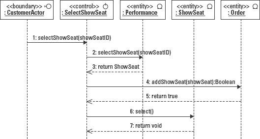
Figure 8-3: Messages are placed on the object lifelines to model object interactions. Relative vertical position indicates the order of execution from top to bottom.
 The placement of the arrows on the timeline does not imply any specific measurement of time. Only the relative position matters, that is, if one message is placed on the timeline above a second message, then the first message is sent before the second message.
The tail of the message arrow identifies the sender. The head of the message arrow identifies the receiver. Reading from top to bottom, the Sequence diagram in Figure 8-3 reads as follows:
- The customer selects the show seat she wants to purchase, presumably from a user interface, passing the identifier for the show seat to a control object, an instance of SelectShowSeat. The control object is basically an event handler in this scenario.
- The control object, SelectShowSeat, asks the performance object for a reference to the show seat that matches the provided identifier.
- The performance returns a reference to a show seat object based on the showSeatID passed to it.
- The control object tells the order object to add the selected show seat to its list of ordered show seats.
- The order returns a Boolean value of True saying that everything worked properly.
- The control object then tells the show seat object that it has been successfully selected. This causes the show seat to change its status from not sold to sold.
- The show seat returns void, that is, nothing. (In some cases you would return some values but this provides an example of how you can use a void return.)
Building the Sequence diagram is easier if you have completed at least a first draft of the Use Case model–the diagram and associated use case descriptions (see Chapter 12) and the Class diagram. From these two resources, you can find sets of interactions (scenarios) and a pool of candidate objects to take responsibility for those interactions.
The sequence numbers at the beginning of each of the messages are optional but they are very helpful when you need to discuss the diagram or make changes. Later, I explain the full message description that can make use of message numbering. The numbers are also useful when working with multiple scenarios that use some of the same messages. For example, if the first 7 steps of scenario #1 are the same in scenario #2, then scenario #2 could simply refer to the first seven steps by number in a comment icon rather than have them redrawn. Fortunately, many modeling tools simply take care of the numbering for you.
Reusing common interactions is a significant addition to the features of UML 2.0.
Each solid arrow describes a message using formal operation notation. The operation defines the interface required by the receiving object, the object whose timeline the arrow is pointing to. In order to be received, the message must conform exactly to an interface (an operation signature) defined on the class to which the receiving object belongs. The syntax for a message is as follows:
predecessors ‘/’ sequence-term iteration [condition] return
‘:=’ operation
The expression predecessors, followed by a slash (/), refers to a list of comma-separated sequence numbers of messages that must come before the current message. The list implies synchronization, that is, the predecessors must be completed before the current message may proceed. Immediate predecessors on the diagram are assumed so they don't need to be included. In a simple sequential flow of control, the predecessors are not needed because each message follows immediately after the previous message.
The sequence-term may be either a number or a name. Numbers are far more common. Specific schemes for numbering vary widely. Most use the dot notation to model nested levels for calls, for example, 3.1, 3.1.1, 3.1.2, 3.1.3, and so forth.
Iteration and conditions are explained a bit later in this chapter.
The return may include a list of values sent back to the sender by the receiver. For example, message 4, addShowSeat(showSeat):Boolean, in Figure 8-3 defines a return type of Boolean. Message 5 returns the Boolean value true. Another scenario would return a Boolean value of false. Note that the return arrow is drawn using a dashed line and a stick arrow to distinguish it from the synchronous message arrow. The choice whether to show the return varies among UML practitioners. Some place a priority on saving steps so they leave the returns off of the diagram. Others focus on clarity so they always include them. When modeling scenarios, it is useful to reveal the values that cause the scenario to execute in a specific manner, like the True and False paths mentioned in the last example. There are also times when not showing the returns causes some ambiguity in the interpretation of the interactions. I provide an example of how the lack of returns can cause ambiguity in the interpretation of the diagram a bit later in the “Self-reference message” section.
The operation defines the name of the operation, optionally the parameters, and optionally a return. Parameters are not required; when used, they follow the attribute definition format of name ‘:’ type, and may even specify defaults and constraints.
Chapter 5 provides a complete description of the operation syntax.
Creating all these arrows, messages, and returns might sound like a lot of work, but consider two things. First, you have to define all of this information anyway to write an application. This way you have a visual record of how you decided that the way you wrote the code was the best way to write it. Second, consider the process. You define a class. Then you create a few Sequence diagrams. Each adds some new operations to the class. Soon, building additional Sequence diagrams becomes a process of drawing message arrows and simply choosing from a list of existing operations on the class. The process starts slowly but quickly picks up speed as the class definitions become more complete.
Having explained the full message syntax, I have to say that most Sequence diagrams depict only the operation portion of the message.
Stimulus, message, operation, and signal
To understand the various message types and notations that can be used on a Sequence diagram you need some basic definitions. Stimulus, message, operation, and signal make up the vocabulary for working with interactions between objects in both Sequence and Collaboration diagrams. A stimulus is an item of communication between two objects, and has the following characteristics:
- A stimulus is associated with both a sending and a receiving object.
- A stimulus normally travels across a link. However, when the stimulus is sent and received by the same object, there is no link. This kind of stimulus is called a self-reference.
- A stimulus may invoke an operation, raise a signal, or even cause an object to be created or destroyed.
- A stimulus may include parameters/arguments in the form of either primitive values or object references.
- A stimulus is associated with the procedure that causes it to be sent.
In contrast, a message is the specification of a stimulus. The specification includes the roles that the sender object and the receiver object play in the interaction, and the procedure that dispatches the stimulus. So technically speaking, a stimulus is an instance of a message. In the parts of the UML specification that cover Sequence and Collaboration diagrams, the two terms stimulus and message are almost always used synonymously (note that I did say almost).
When using a tool to model the Sequence and Class diagrams, you only need to define the features required to generate the code. Namely, for each message you need to define either the operation signature (as described in Chapter 5) or the information returned from a message. The operation explains the procedure that the message invokes on the receiving object. The return contains the information passed back from the receiver to the sender. An empty return is valid.
A message may raise a signal. This means that the message may be no more than an alert like a doorbell, an alarm, or a message box on a computer screen. It does not require a return message. The implications of this type of message are explained more fully in the “Asynchronous message” section of this chapter. A signal is a type of class associated with an event that can trigger a procedure within the receiving class. In this respect it is just like a message. The fundamental difference is that it does not require a return from the receiving object.
An exception is a type of signal. Throwing an exception means sending out a message containing an object that describes the error condition. This means that throwing an exception is a behavior that may be modeled using a Sequence diagram, or any other behavior diagram. For example, in Figure 8-3, message 5 returned a Boolean value of true. In another scenario for the same process, we might need to return a value of false, but that value would not tell us what actually happened that made it fail. Since exceptions may be user-defined, an exception object could encapsulate any information you want to capture about an error condition. So an alternative approach would be to throw an exception that could be caught by either the calling object or another object higher up the call sequence (stack).
The throw/catch approach to exceptions is common to most object-oriented languages. It allows errors to be defined as objects that encapsulate any and all information needed to fully describe the problem, instead of limiting errors to a simple true or false value or an error code. This approach also separates the problem of where to trap errors from where and how to handle them.
A message may also indicate the creation or destruction of an object. How a message does so is explained later in the “Modeling object creation and destruction” section.
Synchronous message
So far I have used only synchronous messages in the examples. A synchronous message assumes that a return is needed, so the sender waits for the return before proceeding with any other activity. Messages 1, 2, 4, and 6 in Figure 8-3 are all synchronous messages.
The dashed return arrows marked as sequence numbers 3, 5, and 7 in Figure 8-3 each represent only the reply to a message, called a return. The return value is placed on the return message arrow. For code generation, a return may only have one value such as a Boolean True or False value, a numeric value, an object (reference), or a string. Technically, UML allows a list of values.
When creating your initial model, don't be concerned that the return ultimately needs to be limited to a single value. Focus on discovering the information that needs to be passed. Put as many values as you need in the return. Once you are sure that you have the right information, you can always package/encapsulate the multiple values into an object such as a transaction.
Some folks leave the returns off of synchronous messages, choosing to assume the return. But showing the returns can help ensure that what you're getting back is consistent with what the test case required and what the message/operation requires. Remember that a primary value of models is the ability to review them with other people to solicit observations regarding the accuracy, completeness, and efficiency of an approach to a problem. People can't make observations about what they can't see and often make different assumptions than you might have made.
Self-reference message
In a self-reference message, the sender and the receiver for the message are the same object. For example, a user object might send a “cancel” message to a theater event object. The event must change its own status and the status of each performance within the event. Since an event might have to cancel an individual performance for other reasons, it makes sense to make the ability to cancel a performance a separate operation that could be called under either circumstance. Doing so enables the same event operation, cancelPerformance(), to be called once to cancel one performance for the event, or called multiple times to cancel all performances for the event, or even for a time frame within the event.
Figure 8-4 models a portion of the Sequence diagram that calls cancel() on the event object, which in turn causes the event to call the cancelPerformance() operation on itself. Note that the message arrow leaves and comes back to the same lifeline. This is called a self-reference—the event object is referring to itself when it makes the call. Note too that message 2 is only the invocation. The return is a separate message (5) drawn the same way. It leaves the event lifeline and comes back to the same event lifeline. In other words, messages 2 and 5 say that the event object is telling itself to start the cancelPerformance() process, and then telling itself when it has finished. The event object initiates and responds to the message.
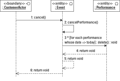
In message 3, the asterisk indicates iteration and the expression [for each performance whose date is => today] is a condition. Both concepts are explained later in this chapter.
A common mistake is to think that the self-reference is a send and return in one message, that is, the portion of the arrow leaving the lifeline is the invocation message and the portion of the arrow returning to the lifeline is the return from the message. But each arrow is a single message from one sender to one receiver. The send and return cannot be combined into one message.
When a message appears only as a self-reference, it says that the operation is only invoked from within the object's own behaviors. This is a good indication that the operation might be set to private access to ensure that the use of the operation is limited to within objects of the same class. Be sure to check all of the Sequence diagrams where the operation is called to be certain it never needs to be called by another object directly.
Figure 8-4 is also a good example of why showing returns can remove ambiguity. It is obvious from the model that message 3 returns before message 2 finishes. But if I remove the returns, there is no way to know whether message 2 must finish before sending message 3.
Asynchronous message
Earlier I referred to signals as messages that do not have a return. Another name for this type of message is an asynchronous message. An asynchronous message says something about the responsibilities of the sender and receiver. The sender is responsible only to get the message to the receiver. It has no responsibility or obligation to wait to find out if or how the receiver will respond. The sender may simply go about its business. The receiver may decide to do nothing or to process the received message.
In these respects an asynchronous message resembles the way you receive mail. The postman delivers the mail without any regard for what you do with it once you get it. You can choose to throw away the junk mail, keep and pay the bills, respond to letters from people you like, and ignore the mail from those you don't like. Regardless of your choice, the postman continues delivering mail to other people. In contrast, a synchronous message is like a letter sent by messenger requiring a signature. The messenger waits on your doorstep until she gets a reply from you.
An asynchronous message is modeled using a solid line and a stick arrowhead to distinguish it from the solid arrowhead of the synchronous message. (You might also see half arrowheads in some tools. This was the notation from UML 1.3 and earlier). The content of the message is an operation, the same as for a synchronous message. The only difference is that there is no return (in many languages this means the return is specified as void).
In Figure 8-5, message 3, the theater system obtains a list of events from a venue object. It then tells the boundary object CustomerActor that represents the user interface to display the events. It does not wait to find out if or how the user interface displays the events. Contrast this with message 1, getEvents(start, end). This is a synchronous message that requires a specific response. The theater system actually stops whatever else it might be doing until it receives the list of events or an error.

Figure 8-5: Asynchronous event.
Another way to understand the asynchronous concept is that nothing else the sending object does is contingent on the reaction of the receiver. This approach can actually make an application a bit easier to design. For example, the theater system can continue with other work while assuming that the user interface is working just fine. The theater system only gets involved if it receives a thrown exception or other signal from the user interface. The alternative would be to design the theater system object to wait for a response for every message it sends to the user interface.
Comment
Sometimes you might want or need to provide some explanation for the diagram or elements within diagram, but UML notation does not provide the specific means to do so. What you really need is the chance to simply write some freeform text to get your point across. Figure 8-6 shows how you might use a UML comment icon (a rectangle with a folded corner) to add information that is not explicitly part of the notation. A comment may be placed anywhere on or around the diagram. Optionally, the comment may be attached to an element of the diagram using a dashed line called an anchor.

Figure 8-6: A comment on a Sequence diagram.
UML 2.0 changed the name from comment to note.
Timed message
Often there is also a condition or a constraint on a message that expresses the timing parameters for the message, for example, {if you don't get a response from the event object within 2 seconds, bypass the request and send an error to the user interface}. In order to evaluate this constraint, you first need a means to measure time. A message may have any number of user-defined time attributes, such as sentTime, receivedTime, and elapsedTime. But to access these values you need to identify the message that owns the value by using either a message number or a message name. For example Figure 8-7 uses message names instead of numbers.
Figure 8-7 models a phone connection from the time a person picks up the receiver to make a call until the time someone picks up to answer the call. Each message is assigned a name: a, b, c, and d. The caller lifts the receiver; this sends message a (lift receiver) to the exchange. The exchange sends message b (dial tone) to the caller's phone. To the left of messages a and b is a constraint, {(b.receiveTime – a.sendTime) < 1 sec.}. The constraints tells us the design must provide a response time of less than 1 second between the time the lift receiver message is sent (the tail of the a:lift receiver arrow) until the dial tone message is received (the head of the b:dial tone arrow).
Place the constraint in the left margin of the Sequence diagram next to the period of time that it constrains.
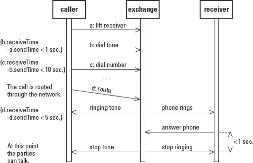
Figure 8-7: Timed messages using constraint notation.
©OMG 1.4
In most Sequence diagrams you model the arrows horizontally as though the messages are instantaneous. Message d:route illustrates a way to model a message that requires a significant amount of time, and that you want everyone reading the model to be very aware of it. Simply slant the arrow from the tail down to the head. Again, place the time constraint in the left margin. The arrow is simply a visual cue; it doesn't designate any specific amount of time. This is why you must use a constraint to provide the timing requirement.
Not every tool supports the left-margin approach. You might need to use comments and type the constraint into the comment. Other tools support constraints in the specification of the message, an approach that is not as flexible or visible but is more precise.
The timed message is an example of the use of a UML extension mechanism, namely the constraint. A timed message is not a part of the core UML notation but it represents a valid usage of the UML constraint notation to extend the features of the basic Sequence diagram.
Iteration
Iteration refers to the need to execute one or more messages in a sequence more than once. Iteration on a single message is molded using iteration symbol, an asterisk (*), and a condition to control the number of iterations. Figure 8-8 shows how you can indicate that an operation should be performed repeatedly.

Figure 8-8: Modeling iteration on a message.
There are actually two components of the iteration notation that are placed in front of the message text. An asterisk (*) indicates that the message will execute repeatedly. If you want to explain how to control the iteration you can enclose a conditional statement in square braces ([ ]). Message 3 in Figure 8-8 reads, “*[for each show seat],” meaning that the same message is sent by the performance object to a show seat object for every show seat object in the location (the set of show seats) passed to the performance in message 2. The conditional expression may be a Boolean expression or freeform text.
Executing a message repeatedly implies executing all of the subordinate messages repeatedly as well. In other words, if message 3 in this example required sending a message to three related objects as well, the block of messages would be executed repeatedly. Another technique commonly used in this case is to enclose the set of repeated messages in a box and place the condition in the box. This approach might not be supported by every tool.
Conditions
Conditions are used to specify the control of the iteration. However, conditions may be used pretty much anywhere in the sequence of messages. In fact, if a Sequence diagram models a single scenario, it is almost certain that there are conditions that drive the use of the messages in the scenario. A condition is expressed as text enclosed within square braces [ ].
For example, when a customer selects a show seat that he wants to purchase, it only becomes part of his order if it has not already been selected by someone else. Figure 8-9 models the successful scenario. Message 3 adds the condition [show seat not selected], between the sequence number and the colon, to convey that the performance returns a show seat reference only if the show seat has not been previously selected.
Figure 8-10 models the failed scenario. Message 3 adds the condition [show seat selected] meaning that the performance returns an error because the show seat has been selected. Message 4 is a completely different message than in the first scenario, because the different condition in message 3 caused an alteration in the flow of events.
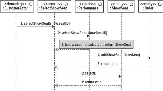
Figure 8-9: Modeling conditions to explain the flow of messages. Message 3 states that if the show seat that is being selected in message 2 has not already been selected, then message 3 will return a reference to the selected show seat object.

Figure 8-10: Modeling an alternative scenario using a condition to explain the variation.
Technically, UML supports the ability to model branching on a decision. This involves drawing a diamond (decision point) and multiple arrows from the same point on the timeline to multiple destinations. But since the subsequent messages could vary widely, you end up with multiple overlapping sets of messages on the same diagram. The diagram quickly becomes indecipherable. It is simpler to stick to the rule that one Sequence diagram represents one logical path or one scenario, and avoid branching altogether.
Modeling activation/focus of control
Sequence diagrams can be enhanced to illustrate object activation and object deactivation. Activation means that an object is occupied performing a task. Deactivation means that the object is idle, waiting for a message. To show that an object is active, widen the vertical object lifeline to a narrow rectangle, as shown in Figure 8-11. The narrow rectangle is called an activation bar or focus of control. An object becomes active at the top of the rectangle. Note that the venue object lifeline becomes active when it begins to do work when the message arrow labeled getEvents points to the venue object lifeline. An object is deactivated when it finishes its work. This is usually illustrated as a message arrow leaving the object lifeline, as when the return events message leaves the venue object lifeline in message 2.
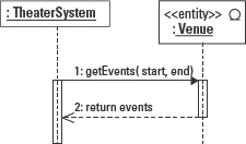
Figure 8-11: Object activation and deactivation.
Sometimes a distinction is made between an activation and a focus of control, although this distinction is not directly supported by the UML specification. It is sometimes useful to recognize that some object remains in control of the entire process modeled by the Sequence diagram. Such an object does more than respond to messages; it oversees the entire interaction set. For example, the theater system object remains active from the time it starts up and sends the first message. It remains active while overseeing the results of the call to the venue and continues to work based on the response it gets from the venue. An object that represents the focus of control has an activation rectangle along the entire length of its object lifeline.
There is an odd practice in modeling tools that is not consistent with the UML specification. Tool vendors tend to put a “tail” on the end of the activation that extends beyond the point at which the activity actually ends. I've yet to find out why.
Recursion
An object might also need to call a message recursively, that is, call the same message from within the message. For example, in Figure 8-8 the priceShowSeat message requires the performance to price every seat in the location passed to it. In the Class diagram for the theater, a location is defined as a set of one or more seats or groups of seats. So a location could mean a section composed of rows, composed of seats. We could modify Figure 8-8 to use a recursive call to the location object instead of separate calls from the performance to each individual show seat.
Figure 8-12 models the recursive call in message 4 utilizing a combination of a self-reference and overlapping activation notation.

Figure 8-12: Recursive message calls.
The larger of the two overlapping activations indicates that the object is busy performing a task (in its duty cycle), that is, the task invoked by message 3. That task then calls itself, so there is another activation on top of the first, offset to the right. For example, if a location is a section in the theater, then the location object calls priceLocation on all of its rows. Each row in turn calls priceLocation on all of its seats. Seats contain no other locations so the calls stop. This technique is common when performing a task against hierarchies or nested collections such as the theater locations, or sales territories within regions, within countries, within global divisions, and so forth.
Modeling object creation and destruction
Finally, to model object creation you have a few options. When I explained the object lifeline notation, I said that the default location for the object icon is at the top of the page. If an object is in this position, it means that the object exists when the sequence starts. If the object is created during the execution of the scenario, it should appear somewhere below the top of the diagram. Some tools do not support this visually accurate approach, so you might see any one of the three variations modeled in Figures 8-13 and 8-14. All three examples model the event object that calls the constructor Performance(event), the operation that creates an instance of the Performance class.
The example on the left is the form explicitly defined by UML 1.4. The creation message/constructor, called Performance(event), points directly at the performance object icon. This means that the object icon has to be placed somewhere below the top of the page indicating when the constructor is actually called.
The example on the right is a minor variation where the constructor points to the object lifeline just below the object, but the object is still placed on the diagram at (or at least near) the point in time when it is created, rather than at the top.

Figure 8-13: Two UML standard visualizations for object creation.
The goal of the notation is to represent the fact that the object did not exist prior to the creation message. The object lifeline literally comes into existence when the creation message is sent, so there is no object lifeline before (above) the creation message. The figure on the left indicates this most clearly.
Some modeling tools can only place objects at the top of the page. Figure 8-14 models the object icon at the top of the page, and must depend on the message description to convey when the object is created.
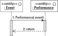
Figure 8-14: Object creation with the created object at the top of the page.
In contrast, to show that an object is terminated, place an X at the point in the object lifeline when the termination occurs. This is usually in response to a message such as delete or cancel. Figure 8-15 models the fact that the performance has been deleted from the system. The absence of the X on an object lifeline means that the object lives on after this sequence of events is ended.

Figure 8-15: Object termination.
Not all tools support this notation. As was true for object creation, you might need to depend on the message description alone to know that the object has been terminated.
Applying the Sequence diagram to the Theater System
Figure 8-16 shows a Sequence diagram for the process of selecting a performance. The TheaterSystem object represents the application that might actually be implemented as a group of objects that control the screen/s, access to the business objects, and so forth. The CustomerActor object represents the user interface that the customer uses when viewing and selecting a performance. The interactions are derived from the interactions that the user expects of the system as documented in the use case. That is, the user expects the system to provide a list of events and a list of performances. The complete use case also supports the ability to request a list of performances by date range, a list of performances for a particular event, and canceling without selecting anything.

Figure 8-16: Sequence diagram for a scenario where a valid selection is made and saved.
A Sequence diagram is most often used to model a single series of interactions, one scenario. Figure 8-16 models a scenario in which the user selects a performance from the initial display of events and performances.
This example does not show the returns on the operations. This is a common option in modeling tools shown here simply to illustrate another of the available options.
In this figure:
- Message 1 is a synchronous message that requests the set of events for a date range. The date range is established by the application. Message 2 returns the set of events.
- Message 3 is an asynchronous message that asks the user interface to display the set of events.
- Message 4 is a synchronous self-reference that initiates the process of accumulating all the performances for all the events selected in message 1.
- Message 5 is an iterative synchronous message to retrieve all the performances for each event.
- Message 8 is an asynchronous message to the user interface to display the performances.
- Message 9 is an asynchronous message from the user interface telling the theater system that the user selected the specified performance.
- Message 10 is a synchronous message to the user interface to get a response from the user to confirm his selection.
- Message 12 is an asynchronous message to save the selected performance.
- Message 13 is an asynchronous message to close the screen.
Modeling a Collaboration Diagram
The Collaboration diagram offers an alternative to the Sequence diagram. Instead of modeling messages over time like the Sequence diagram, the Collaboration diagram models the messages relative to object structure. The Collaboration diagram uses this approach in order to emphasize the effect of the objects and their links on the pattern of interactions. Consequently, the advantage of the Collaboration diagram is that it can help you validate the associations between classes or even discover the need for new associations.
Figure 8-17 is a Collaboration diagram that models the same set of interactions modeled in Figure 8-4 using a Sequence diagram. On a Sequence diagram, the sequence numbers are optional. On a Collaboration diagram, the numbers are essential, since there is no other way to determine the order in which the messages are passed. To read the Collaboration diagram, follow the numbered messages to step through the scenario. Messages 1, 2, and 3 are synchronous messages. Message 2 is a self-reference. Messages 4, 5, and 6 are returns.

Figure 8-17: Collaboration diagram of cancel event scenario modeled in Figure 8-4.
The “Comparing the Sequence and Collaboration Diagrams” section later in this chapter provides more detail about the similarities and differences between Sequence and Collaboration diagrams so that you can choose the diagram that will help you the most with a particular problem in your project.
The Collaboration diagram is built on top of an Object diagram, as follows:
- Place the participating objects on the diagram.
- Draw the links between the objects using the Class diagram as your guide.
- Add a message by placing the message arrow parallel to the link between the two objects. Position the arrow to point from the sender to the receiver. Place the message text on the arrow.
- Number the message in its order of execution.
- Repeat steps 3 and 4 until the entire scenario has been modeled.
Modeling objects and links
The Collaboration diagram uses an Object diagram as its foundation. First, determine which objects will participate in the scenario. Draw the objects with only the name compartment, not the attributes. Then draw the links between them. Any pair of classes may have more than one type of association, for example a person can own a car and drive a car. You need to use the Class diagram as your guide to identify the valid types of links that apply to the current sequence of messages.
Figure 8-18 shows objects and their links. You may leave the link names off of the links when there is only one type of association between the related classes. Add the names if there is more than one kind of link possible between the two objects and there is a need to clarify which type of relationship supports the interaction.
Note that the self-reference in messages 2 and 5 requires a link on the Collaboration diagram even though technically there is no link. A message in general does not require a link when the same object is invoking and responding to the message. This is simply a limitation of the Collaboration diagram notation.

Figure 8-18: Objects and links.
Modeling messages and stimuli
For each step of the scenario, draw the message arrow from the sending object to the receiving object, and parallel to the link between them. Having many messages (arrows) placed on the same link is valid and, in fact, common. With a lot of arrows the link can become crowded and difficult to read so be careful to lay out the diagram so that it can be read and understood. Number the messages in the order in which they occur.
The format for specifying a message is the same as on the Sequence diagram:
predecessors / seq-term iteration [condition] return ‘:=’
operation
Most often however, the message displays only the operation portion of the message syntax. Figure 18-19 models the scenario from the Sequence diagram in Figure 8-16.
The Collaboration diagram provides one other valuable feature. A link may be stereotyped to make it clear whether the link is persistent or transient. The links based on the Class diagram are typically references that persist between executions of the application. A transient link is a reference that only exists during the execution of a task or an application. For example, the link between the TheaterSystem object and the Event objects only exists because the theater system obtained the object references from the Venue. The stereotype «transient» may be placed next to the link between the TheaterSystem and Event objects to make this clear.

Figure 8-19: Messages on a Collaboration diagram.
Active objects
An active object refers to an object that initiates controls or directs other objects. Contrast this with passive objects that simply respond to requests. In Figure 8-19 the Theater System represents an active object, while the Venue and Events objects are passive. To identify an active object, the border of the object is highlighted or thickened. In addition, the property keyword {active} may be placed in the object icon. Figure 8-20 shows both techniques.
In many instances the active object is actually a collection of objects, as is the case with the TheaterSystem object. If you want, you may also expand the TheaterSystem object to a large rectangle, and then model the objects that make up the TheaterSystem inside the rectangle.
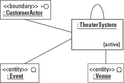
Figure 8-20: An active object.
Multi-objects
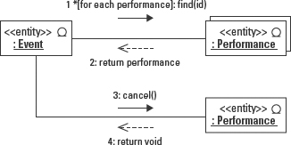
A multi-object is a set of objects of the same type. When you need to perform the same operation on all objects in a set, you can represent the set as an object icon on top of another object icon, offset enough to make it appear as one of a number of objects. The Performance object in the top right corner of Figure 8-21 is a multi-object icon.
Figure 8-21 illustrates a common usage of the multi-object. In order to perform an operation on all members of the set, you typically need to gain access to each member. Message 1 in Figure 8-21 asks for each performance by a unique ID number. Note the iteration symbol on message 1. Then the event invokes message 3, cancel(), on each performance.
Comparing the Sequence and Collaboration Diagrams
Sequence and collaboration diagrams model the same two elements: messages and objects. In fact, the two diagrams are so similar that some modeling tools, such as System Architect and Rational Rose, provide a toggle feature to switch back and forth between the two views.
Like the Sequence diagram, the Collaboration diagram provides a tool for visually assigning responsibilities to objects for sending and receiving messages. By identifying an object as the receiver of a message, you are in effect assigning an interface to that object. The message description becomes an operation signature on the receiving object. The sending object invokes the operation.
All of the message types are supported on both diagrams.
Both diagrams are also excellent tools for evaluating coupling. Coupling is a measure of quality that tests the degree of dependency between model elements. Dependency is clearly seen in the need for communication between objects. If you review all of the diagrams in which a pair of objects participate, you can see how many messages and what type of messages they use to work together. This provides the opportunity to evaluate opportunities to reduce or simplify the communication and improve the design. This is very difficult to do when the only resources you have are the Class diagram or code.
Despite their similarities, the diagrams also have important differences. The Collaboration diagram places a priority on mapping the object interactions to the object links. That is, the Collaboration diagram draws the participating objects in an Object diagram format, laying the messages parallel to the object links. This perspective helps validate the Class diagram by providing evidence of the need for each association as the means of passing messages. In contrast, the Sequence diagram does not illustrate the links at all.
This highlights an advantage of the Collaboration diagram. You cannot draw a message where there is no link, because there is no physical path across which the message can travel. On a Sequence diagram, there is nothing stopping you from drawing an arrow between two objects when there is no corresponding link, but doing so would model a logical interaction that cannot physically take place.
You can also see this as an advantage of the Sequence diagram, in that drawing a message where there is no link reveals the requirement for a new link. Just make certain that you actually update your Class diagram or you won't be able to implement the message illustrated on the diagram.
Another advantage of the Sequence diagram is its ability to show the creation and destruction of objects. Newly created objects can be placed on the object lifeline at the point where they are created. The large X at the end of a timeline shows that the object is no longer available for use. On the Collaboration diagram, the object is either there or it is not. There is no way to indicate creation or termination apart from the description of the message and a constraint. However, since the structure is represented in a static Object diagram layout, it is difficult to be certain when the constraint becomes relevant.
Sequence diagrams also have the advantage of showing object activation. Because the Collaboration diagram does not illustrate time, it is impossible to indicate explicitly when an object becomes active or inactive without interpreting the types of messages.
Integrating the Sequence and Collaboration Diagrams with the Class Diagram
Because the Class diagram is the source for code generation in object-oriented development, you need to map what you find in the interaction diagrams back to the Class diagram. Each message becomes an operation on the class of the receiving object. In the classes in Table 8-2, you can see each of the messages from Figure 8-19 declared as an operation on the receiving objects.
Table 8-2 Updated Class Operations
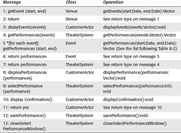
Note the following in reference to Table 8-2:
- Messages map to operations.
- Conditions are placed in the implementation logic of the calling object.
- Iteration logic is placed in the implementation logic for the calling object.
- Parameters and return value identify attributes that need to be defined in a class.
- For each new attribute discovered, the owning class must provide accessor operations to maintain the value and to read the value.
Summary
The Sequence and Collaboration diagrams illustrate communication between objects. The scope of the interactions is typically one scenario, but the diagrams may be used to model interactions at any level of abstraction in the design of a system.
The Sequence diagram models messages between objects on a timeline. The timeline aids in describing the relative order of execution and the addition of time and duration constraints.
- Object lifeline: The object lifeline uses an object icon at the top and a vertical dashed line below the object icon to represent a timeline. The timeline represents the total duration of the interaction.
- Messages: Some messages are predefined by UML; synchronous (solid line with solid arrowhead), asynchronous (solid line with open arrowhead), and returns (dashed line with open arrowhead). Messages are considered to be instantaneous when appearing on a Sequence diagram so they are placed horizontally between object lifelines.
- Activation and Focus of Control: An object is considered active while performing work in response to a message or signal. The dashed line of the lifeline can be widened into a rectangle to represent the active period in its life. An object that oversees an interaction remains active throughout the exchange. This object is the focus of control for the interaction.
- Object creation and Termination: Objects created during the interaction have a lifeline that starts at the point in the vertical timeline of the interaction when the object constructor is called. When an object is deleted or destroyed the lifeline is terminated with a large “X”.
The Collaboration diagram model interactions between objects by illustrating the links that provide the communication paths between the participating objects. The messages must be numbered to define the order of execution.
- Objects and links: Objects and links are represented with the same notation as on an Object diagram.
- Messages: Messages use the same syntax as for Sequence diagrams.
- Active objects: Active objects are modeled with a thick border. Active objects correspond to the focus of control objects on a Sequence diagram. They Initiate the interaction and govern its execution.
- Multi-objects: Interaction diagrams can model the use of a set of objects using a multi-object, an icon that represents a set instead of a single instance.
The information discovered on the interaction diagrams identifies changes to the Class diagram. Reconciling the interaction diagrams with the Class diagram includes the following:
- Messages become operations.
- Parameters and returns become attributes or operations to obtain derived attributes. The owning class must provide accessor operations.
- Conditions become implementation logic.
- Iteration becomes implementation logic.
![]()