
APPENDIX B
UML 2.0 Notation Guide
Class Diagram Notation
The Class diagram notation is explained fully in Chapters 5 through 7.
Class notation

Attribute declaration
[visibility] [/] name [:type] [multiplicity] [‘=’default]
[‘{‘property-string’}’]
The optional underline defines a class-level attribute.
- isDerived: The default value is false.
- isReadOnly: The default value is false.
Operation declaration
[visibility] name ([parameter-list]) ‘:’ [return-result]
 [‘{‘property-string’}’]
The optional underline defines a class-level attribute.
Tagged value declaration
Valid class presentations
Classes may be identified with a name and optional stereotype. The stereotype may be in text or icon form.
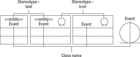
Figure B-2: Four presentation alternatives for classes with stereotypes.
Interface class notation
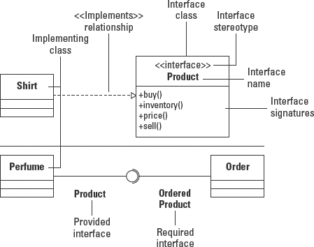
Figure B-3: Interface class notation.
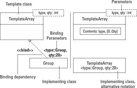
Template class
Parameter syntax
template-parameter ::= parameter-name
[ ‘:’ parameter-kind][‘>’ constraint]
[‘=’ default]
parameter-kind ::=
‘class’ | ‘component’ | ‘type’ | ‘interface’ |‘signal’
|‘value’ |‘operation’ |‘attribute’ |‘part’ |‘class’
| parameter ::= parameter-name | operation-name
( parameter-list )
constraint ::= [‘{contract }’] classifier-name
default ::= classifier-name | expression | attribute-name
| part-name | operation-name
If the parameter-kind is omitted, then parameter-kind is ‘class’.
Bound element syntax
template-name ‘<’ value-list ‘>’
Association notation
Association notation is covered in Chapter 6.
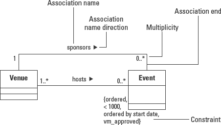
Figure B-5: Binary association notation.
Reflexive association and roles

Figure B-6: Reflexive association and roles notation.
Constraints between associations

Figure B-7: Constraints between associations.
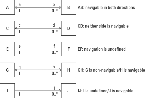
Association navigability
Ordering, derived association, and qualified association

Figure B-9: Ordering, derived association, and qualified association.
Association class notation
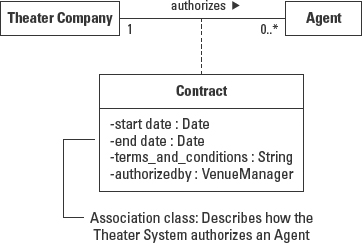
Figure B-10: Association class notation.
N-ary association
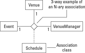
Figure B-11: N-ary association.
Aggregation and composition notation
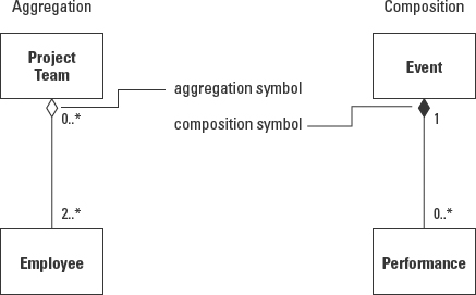
Figure B-12: Aggregation and composition notation.
Composite structure notation
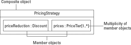
Figure B-13: Alternative composition notation.
Generalization notation
Generalization is explained in Chapter 6.
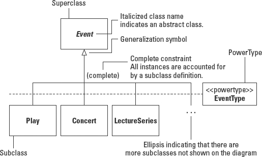
Figure B-14: Generalization notation: complete constraint, Power Type, ellipse, and abstract class.

Figure B-15: Generalization notation: discriminator, disjoint and overlapping constraints, and multiple inheritance.
Dependency notation
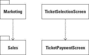
Figure B-16: Dependency notation between two packages (left) and two classes (right).

Figure B-17: Class dependency notation.
Object Diagram
Chapter 7 covers the Object diagram.
Object and link notation

Object name syntax
Object-name : class-name
Attribute value syntax
Pattern/Collaboration notation
Chapter 7 covers patterns and collaborations.
Modeling a design pattern using a collaboration
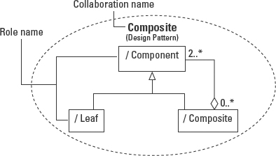
Figure B-19: Using collaboration notation to define a design pattern.
Implementing a design pattern / collaboration
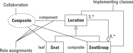
Figure B-20: Implementing a design pattern (collaboration).
Sequence Diagram Notation
The Sequence diagram is covered in Chapter 9.
Sequence diagram (interaction) lifeline, message and return, self-reference, guard, and iteration
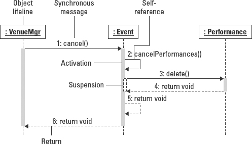
Figure B-21: Sequence diagram basic notation.
Message (and arrow) types
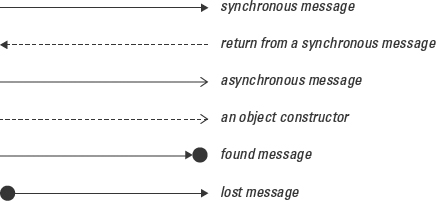
Message syntax
message-ident ::=
signal-or-operation-name [ ( arguments) ][: return-value]
arguments ::= argument [ , arguments]
argument ::=
parameter-name:argument-value | argument-value | -
State invariant

Object creation and termination

Figure B-24: Object creation and termination.
Duration constraints
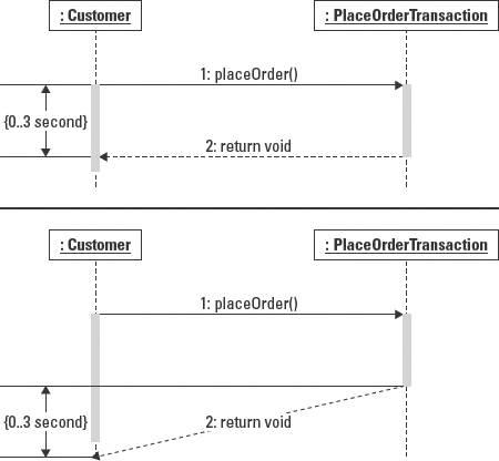
Figure B-25: Duration constraints.
Time constraints

Figure B-26: Time constraints.
Interaction occurrence

Figure B-27: Interaction occurrence.
Gates and parameters

Figure B-28: Interaction occurrence.
Interaction operands and operators
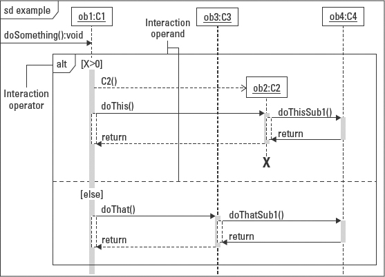
Figure B-29: Interaction occurrence.
Interaction operators consider, ignore, and assert
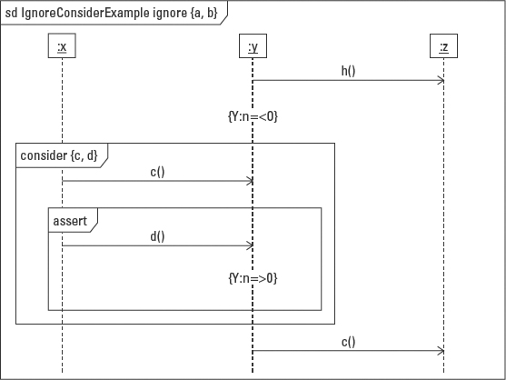
Figure B-30: Interaction operators consider, ignore, and assert.
Communication Diagram
Chapter 9 covers the Communication diagram.

Figure B-31: Communication diagram notation.
Interaction Overview Diagram
Chapter 9 addresses the Interaction Overview diagram.
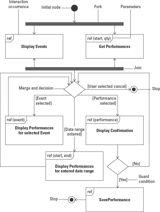
Figure B-32: Interaction Overview notation.

Figure B-33: Interaction Overview lifeline notation.
Timing Diagram
The Timing diagram is discussed in Chapter 9.
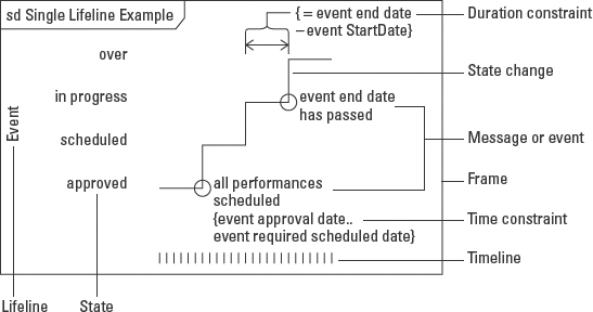
Figure B-34: Timing diagram notation.
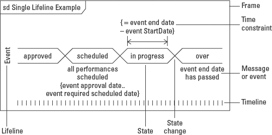
Figure B-35: Timing diagram alternative notation.
Statechart Diagram Notation
Chapter 11 discusses the Statechart diagram.
Initial and final state, state, transition with guard

Figure B-36: Statechart notation (1).
When and after clauses
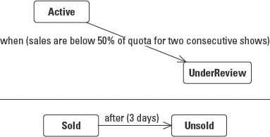
Figure B-37: When and after clauses.
Transition syntax
Event-name (comma-separated-parameter-list)
[guard-condition] / action-expression
Self transition, and entry and exit actions
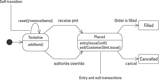
Figure B-38: Self-transition, and entry and exit actions.
Static branch state

Figure B-39: Static branch state.
©OMG 2.0
Dynamic choice point

Figure B-40: Dynamic choice point.
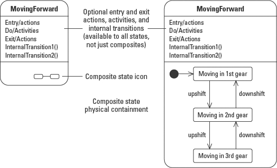
Composite state
Deep and shallow history
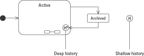
Figure B-42: Deep and shallow history.
Concurrent substates
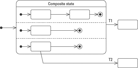
Figure B-43: Concurrent substates.
Split and merge of control

Figure B-44: Split and merge of control.
Submachine state and stub states

Figure B-45: Submachine state and stub states.
Synch states

Figure B-46: Synch states (Sync state still appears in the UML 2.0 glossary but is not part of the UML 2.0 specification.)
Action specification with send and receive signals
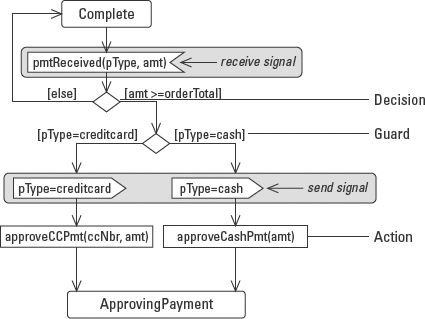
Figure B-47: Action specification with send and receive signals.
 The gray highlighted rectangles are for emphasis only.
Activity and completion transition

Figure B-48: Activity and completion transition.
Two ways to model common transitions
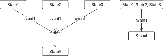
Figure B-49: Two ways to model common transitions.
Protocol state machine and generalization
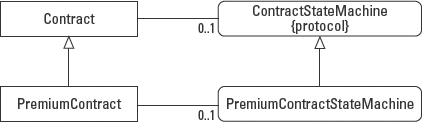
Figure B-50: Protocol state machine and generalization.
Use Case Diagram
The Use Case diagram is covered in Chapter 12.
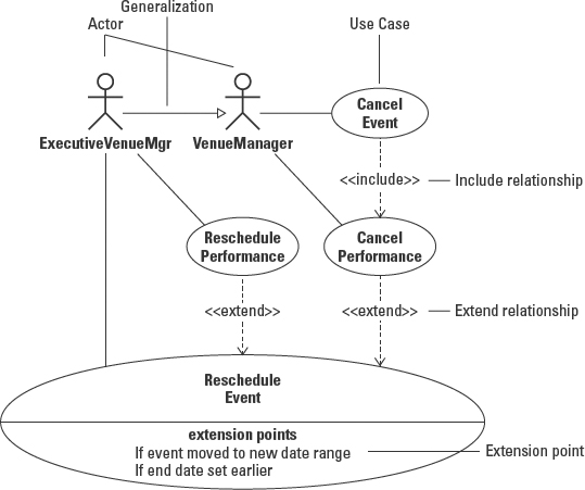
Figure B-51: Use Case diagram notation.
Activity Diagram
Chapter 13 has details on the Activity diagram.
Start, end, decision (split), and merge

Figure B-52: Start, end, decision (split), and merge.
Concurrency using fork and join nodes
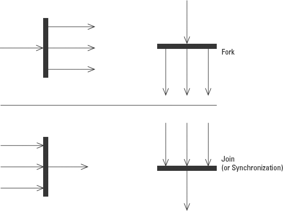
Figure B-53: Fork and join notation.
Activity, transition, and transition guard
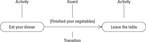
Figure B-54: Activity, transition, and transition guard.
Component Diagram
Chapter 15 discusses the Component diagram.
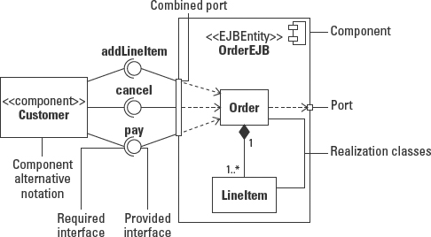
Figure B-55: Component diagram notation.
Alternative notations for realizing classes

Figure B-56: Alternative notation for realizing classes.
Deployment Diagram
Chapter 16 provides details on the Deployment diagram.

Figure B-57: Nodes defined as classifiers, with attributes and operations, at type and instance levels.
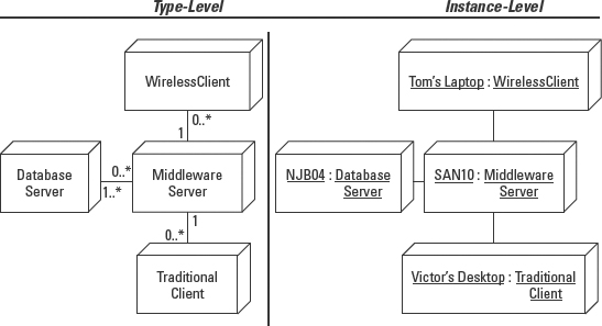
Figure B-58: Component diagram at type and instance levels.
Combined Component and Deployment Diagram
This topic is covered in Chapter 17.
Artifacts that implement components

Figure B-59: Artifacts that implement components.
Component deployment on a node instance
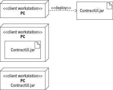
Figure B-60: Deployment of a component on a node instance.
Deployment specification

Figure B-61: Deployment specification.
Deployed components
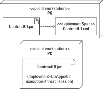
Figure B-62: Deployed components.
Packages
Basic Package diagram
Packages as namespaces
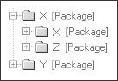
Figure B-63: Packages as namespaces.
Package containment notation alternatives
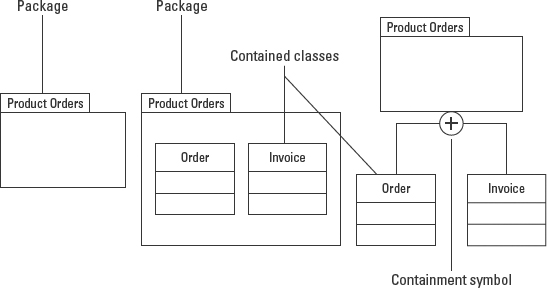
Figure B-64: Package containment notation alternatives.
Access dependency

Figure B-65: Access dependency.
Merge dependency

Figure B-66: Merge dependency.
Subsystem diagram
Subsystem notation alternatives

Figure B-67: Subsystem notation alternatives.
Subsystem interface notation

Figure B-68: Subsystem interface notation.
Subsystem realization
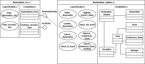
Figure B-69: Subsystem realization.
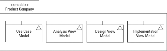
Model diagram
Model notation
![]()