
CHAPTER 5
Capturing Rules about Objects in a Class Diagram
![]()
In This Chapter
- Exploring the purpose and function of the Class diagram
- Defining and modeling the class compartments
- Defining and modeling class attributes
- Defining and modeling class operations
- Defining and modeling user-defined class compartments
- Defining and modeling advanced class features—interfaces, and class templates
![]()
The Class diagram stands at the center of the object-modeling process. It is the primary diagram for capturing all the rules that govern the definition and use of objects. As the repository for all the rules it is also the primary source for forward engineering (turning a model into code), and the target for reverse engineering (turning code into a model).
The Class diagram is described in this chapter and in Chapter 6. This chapter covers classes and all the features used to describe them. Attributes and operations describe the knowledge and behavior of a class. Additional embellishments such as stereotypes, tagged values, and constraints describe how you can customize classes to facilitate development in a particular domain. Chapter 6 describes how to model relationships between classes.
I cover the UML 1.4 description of classes, attributes, and operations, and step through the UML 2.0 specification to explain the current definitions for classes, attributes, and operations, and the key definition elements such as visibility, changeability, multiplicity, default values, and properties.
Defining the Purpose and Function of the Class Diagram
The Class diagram is probably the most widely used diagram of the UML. In fact, the Class diagram is the primary modeling tool for describing UML itself.
 When I discuss UML 2.0 elements, I refer to the Class diagrams in the UML 2.0 specification to explain the features. This gives you some practice reading and interpreting the diagrams while you familiarize yourself with the specifications.
The Class diagram is also the primary diagram for generating code. While there have been valuable applications that support code generation from State and Sequence diagrams, these tools are not in the mainstream. This ability to generate code places the Class diagram in a unique position relative to all the other diagrams. Figure 5-1 shows all of the UML diagrams, with the Class diagram at the center. It illustrates that even though each of the other diagrams help modelers discover valuable information about a subject, everything they uncover must somehow make its way onto the Class diagram.
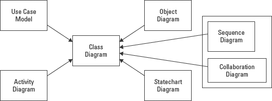
Figure 5-1: All other diagrams feed information to the Class diagram.
Chapter 3 describes the purpose and function of each of the UML diagrams. Apart from the Component and Deployment diagrams, which are used to describe the implementation environment, all the diagrams model facts at the object level. These facts come from test cases and examples that help us understand how things work. Facts are invaluable resources, but to build a software application the modeler has to create a set of abstractions, rules, and concepts that describe how these facts may be used. The abstraction needs to define what each resource is, the information it owns, what it can do, and the other types of resources with which it needs to interact to do its job correctly. Figure 5-2 represents how the UML diagrams uncover facts that support the creation of the Class diagram. The Class diagram models the facts so that the model represents reality as closely as possible. The Class diagram defines the code that generates the objects. The objects conform to the Class diagram.
The other UML diagrams model facts as objects. These objects either conform to the rules set forth in the Class diagram, or they reveal the need for corrections to the rules.
The rules in the Class diagram are used to generate code. The code generates objects, while the application is running, that behave according to the rules defined by the Class diagram.
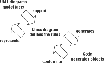
Figure 5-2: The relationships between the Class diagram, other diagrams, and the application code.
Systems may be fairly complex and may require more than one Class diagram. In fact, it is very common to break a subject area down into a set of smaller Class diagrams. Smaller diagrams are easier to work with and easier to verify. But no matter how many diagrams you use for the system, each class has only one definition. A class represents the same concept no matter where or how often it appears in the diagrams. In a modeling tool, this is accomplished by using a repository. A repository is a shared dictionary, usually built into the modeling tool, of all of the information defined during the modeling process. The first time you add a class to a diagram, a definition is placed into the repository by the tool. Each subsequent time that the class is referenced on a new diagram, the new reference is associated with the existing definition. Consequently, a change made to a class on one diagram is also made to the class definition in the repository, and is reflected in all diagrams that include that class.
Defining all of these rules sounds quite complicated. In truth, the notations of the Class diagram provide a surprisingly simple yet powerful means to specify everything needed to generate code. With rigor and the proper software support, the Class diagram can even become fully executable. This means that the model can be tested by executing scenarios and can even generate the complete application in a variety of implementation environments. But I'm getting ahead of myself.
Figure 5-3 illustrates how the Class diagram uses simple rectangles and lines to represent the resources that make up a system (rectangles) and the relationships between the resources (lines). It has been my experience that, even without prior experience, most participants on a team can quickly learn to read the basic notations of the Class diagram. The portion of a Class diagram shown in Figure 5-3 models some relationships in a theater system. The Class diagram represents the resources needed to support scheduling events at a venue and selling access to the seats in the venue that hosts the events. The numbers and all other notations are explained later in this chapter.
The simplicity of the Class diagram can be a bit deceiving. The Class diagram can be used to model a surprisingly wide variety of systems, such as airplane navigation, monthly invoicing, real-time embedded devices such as medical equipment, and human-machine interface systems used to automate factories. But all of these applications rely on the same small set of descriptive elements: classes and relationships. With the addition of the standard UML extension mechanisms (covered in Chapter 3), the Class diagram can model pretty much anything you need in a business or technical environment.

Figure 5-3: A simple Class diagram of the relationships between the resources Venue, Event, and Seat.
Modeling a Class
Classes form the foundation of the Class diagram. So to work with the Class diagram, you need to be clear on the difference between classes and objects. A class is a definition for a resource. It includes information that describes the features of an entity and how it can be used. In contrast, an object is a uniquely identifiable entity that conforms to the rules defined by the class. In software terms, code is written as a set of classes and references to behaviors defined by the classes. The information actually created and manipulated is owned by objects that conform to the class descriptions. Objects are represented by rows in a database, records in files, or areas of memory in a computer.
 Chapter 4 explains the concepts of classes and objects fully.
A class is very much like a dictionary entry. If our theater application has to manipulate information about events, then we first need to explain what we mean by the term event using a class definition. A UML Class definition describes a type of object. In fact, the term “type” is often used as a synonym for “class” (even though there is a subtle difference that will be covered when we get to inheritance in Chapter 6). One class definition describes many objects of the same type. Each class definition contains at least a unique name. This name defines the class in the repository so that any time the same name is referenced it is associated with the same repository definition. A class can also contain attributes and operations that describe everything necessary to create (instantiate) an object of the defined type.
To support definitions for identity, attributes, and operations, a UML class definition provides an icon with three predefined compartments to contain and organize this information: name, attributes, and operations. These compartments (see Figure 5-4) correspond to the common elements of a class definition. In addition, UML supports user-defined compartments so that the modeler can add project-related information or anything else that she finds useful.
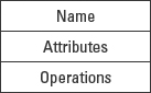
Figure 5-4: Three predefined class compartments.
When a class is presented on a Class diagram, the name compartment is the only compartment that must be visible. The attributes, operations, and user-defined compartments may or may not be displayed, depending on the purpose and goals for presenting the diagram. Figure 5-5 illustrates the available options for presenting the class compartments.

Figure 5-5: Valid presentation options for classes.
Hiding the other compartments does not change the fact that they exist. It merely enables you to keep the people who are reviewing your Class diagram focused on the elements about which you need their insights. Many modeling tools offer this flexibility with simple settings to display or hide compartments and elements as you wish.
The compartments other than the name compartment are simply lists. In fact, the attributes compartment, the operations compartment, and user-defined compartments all derive from the ListCompartment metaclass. In all list compartments, the name of the compartment may be placed at the top of the compartment, but since the attributes and operations compartments are standard, we usually leave off the name and rely on position within the class icon as illustrated in Figure 5-5. The name compartment is at the top. The attributes compartment is directly below the name compartment, and the operations compartment is directly below the attributes compartment.
Modeling the Name Compartment
The name compartment provides a means to uniquely identify a class using a noun or noun phrase like Venue, Event, or PricingStrategy. Figure 5-6 shows three classes. Each class rectangle is divided into three compartments. The name always resides in the topmost compartment. But remember that you may display the name compartment by itself.

Figure 5-6: Classes with names only.
Class name
The name of a class is very important. The name is the primary means for people to recognize a fundamental resource in the model. The name should be an accurate and concise descriptor for the type of object represented by the class. The name is nearly always a singular noun or noun phrase such as Venue, Event, or PricingStrategy. The exceptions to this rule include classes that represent collections of objects, such as Agents, where an instance or object of this type is in fact a list or collection of people-type objects who are associated with a Venue as its “agents”. You could think of it like a list that you keep on file with the Venue so that when you schedule a new Event you can easily contact all the agents.
The capitalization rules for a class name typically correspond to the standards established by your organization for the targeted programming language, that is, the language that will be used to code the application. Since the code generated from these names usually does not support spaces in the name, it is a good idea to use underscores or hyphens or simply no spaces between the words, whichever method is dictated by your programming standards. Every modeling tool that I know of will generate class names (and attributes and operations) exactly the way you type them into the Class diagram. Sticking to the standards early in the modeling effort prevents reworking the model later on.
Although it is not a part of UML notation, a written definition of the class can be very valuable. A written definition can quickly put to rest much of the debate regarding what properties should be included in the class definition. Much of the confusion in modeling comes from the fact that participants in the project each have different preconceived ideas about the meaning of each model element. In the theater example, for instance, one person could assume that an event means a one-time performance. Another modeler assumes that an event is like a play or concert with many performances. Still another assumes that an event refers to a marketing campaign.
As an illustration, I heard once that Eskimos have more than a dozen different words for what we call “snow”. My immediate reaction was to ask “Why so many words?” The answer lies in their need to understand snow. Their survival depends on their ability to adapt to and use the snow effectively. They need to understand the differences between snow that they can walk on, snow that they will sink into, snow that hides ice beneath, snow that can be used to build shelters, snow that foretells a serious storm, and much more.
This is true for people who work with the same concepts every day. I once went to work for an insurance company thinking that I knew what an insurance policy was; foolish man that I am. During the rewrite of the insurance system, I had to collaborate with people from the sales, billing, and claims areas of the company. I never dreamed that there were so many unique ways to view an insurance policy. More than that, all of the perspectives were completely reasonable given the purpose that each participant had in mind. Therein lies the key. Purpose drives the definition of an object. The purpose of an object may be different within different systems or applications.
An accurate definition of the purpose of the class drives every decision about the class during the modeling process. The purpose explains why the object is part of the subject area and why it is important to the project. An accurate definition of the purpose reduces or eliminates debate. In practical terms, an accurate definition can guide the selection of properties that support the purpose of the class. This approach, that is, using the definition as the scale on which to weigh the value of each property, helps ensure high cohesion in the class, a primary measure of quality for the model. (Cohesion is discussed in Chapter 4.)
A little care in this early stage of modeling can pay large dividends throughout the rest of the modeling process. Alternatively, poor naming and definition breed needless debate and wasted time.
The following are some examples of poor class names:
These names embed attributes of the objects in the name. A better way to name them would be to refer to the object Event and provide access to the attributes that can be used to distinguish events from one another. In other words, separate the identity of the type of object (Event) from attributes that describe it (Show.status, Event.nbr_of_shows, and Employee.exempt_status), as illustrated by the classes in Figure 5-7.

Figure 5-7: Separating identity from attributes in a class description.
I explain the entire notation to define the attributes in the “Modeling the Attributes Compartment” section later in this chapter. For now, simply note the difference between defining what an object is and identifying what you know about it. The name defines identity and purpose. The attributes and operations define knowledge and capabilities.
Now you might want to challenge me regarding the class names Exempt_Employee and Non-Exempt_Employee. You would be right to do so. They could actually be valid in the right context. In fact, UML provides a mechanism called specialization to handle exactly this type of situation. The rules for when and how to apply specialization are very well defined. I'll cover the UML definition of specialization and the associated rules for handling this situation in Chapter 6 when I explain inheritance.
A class name must be unique within a package. But the same class name may occur in multiple packages. To clarify which class you mean to reference you must qualify the class name with the name of the package that owns it. The format for a fully qualified class name is Package_Name :: Class_Name, as shown in Figure 5-8 in the fully qualified names Scheduling :: Event, Sales :: Event, and Contract_Admin :: Event. The two names are separated by double colons. The phrase “class path” is also used to mean a fully qualified class name. “Path” refers to the path through one or more nested packages to access the class. In Figure 5-8 the package names are Scheduling, Sales, and Contract_Admin.
The three classes in Figure 5-8 are three distinct definitions even though they all share the class name, Event. This redundancy often happens when systems are worked on by different teams or developed as parts of different projects, or when integrating in-house and vendor products.
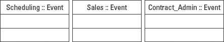
Figure 5-8: Fully qualified class names.
An unqualified class name, for example, Event, is interpreted to mean a class defined in the current package or a class that has been imported.
If the class is imported, you do not need its path (package name), because the import action defines the package name (access path) for all classes in the package. For example, the theater sales application needs access to the seating arrangements defined in the VenueManagement package. The sales application can simply import the entire VenueManagement package and have access to any or all of the classes defined in it.
The fully qualified name is needed only if the current package and the imported package both have a class by the same name. For example, the Sales and VenueManagement packages both define a Seat class. Classes within the Sales package would then need to fully qualify the VenueManagement Seat class as VenueManagement :: Seat.
If the class is referenced but not imported, you must use the path name. A reference does not first establish the access as an import action does, so the path must be explicitly defined. For example, the Scheduling system just needs access to the Venue class. So the scheduling application references the Venue class using the fully qualified name VenueManagement :: Venue.
Stereotype
UML enables you to further define a class using a UML stereotype, which is yet another way to identify how a class is used in a design. For example, when modeling a business application it is common to draw a distinction between classes that describe entity elements and those that describe control elements. An entity element describes objects that are part of the subject matter represented by the Class diagram, such as venues, events, and seats. Control elements typically represent specialized pieces of software that manage the behavior of some part of the application, such as screen navigation or scheduling. UML models a stereotype by enclosing the name in guillemets (French quotation marks) as in «entity» or «control». If you can't map the specific keyboard characters it is acceptable to use two less than (<) and two greater than (>) symbols, such as «entity».
Stereotypes are covered fully in Chapter 3 under “UML Extension Mechanisms.”
A class stereotype is not part of the class name and does not generate any code for the class. The intent of a stereotype is to bring consistency to the treatment of common elements in UML diagrams. Stereotypes do so by defining a purpose and a limited number of expected properties for the set of model elements (in this discussion that means classes) that share the same stereotype.
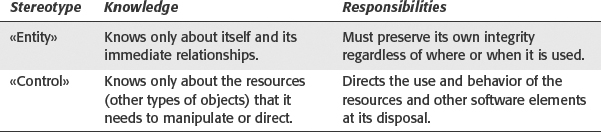
For example, every class with the «entity» stereotype is understood to play a very specific role within the system design. That is, each entity class represents a resource in the real world, outside of the software. An entity class contains properties that describe its features and their current condition (their state). To protect its integrity, an entity type of class also contains behaviors that control access to those properties. Finally, entity classes typically have little or no knowledge of their surroundings other than their immediate relationships. This limited knowledge is part of what makes them so highly reusable. For example, a venue is an entity, a resource used by the theater system. No matter what the theater system uses a venue for, a venue object provides all of the same features and capabilities like capacity, seating, lighting and sound support, and so on.
In contrast, a class with a «control» stereotype owns almost no information about itself. It represents a behavior rather than a resource. Further, a control-stereotyped class is more concerned with directing the behavior of other objects and has almost no behavior of its own. The contrast between «entity» and «control» stereotypes is summarized in Table 5-1.
Table 5-1 Comparison of «entity» and «control» Stereotypes
To apply this additional level of definition to the class, the UML places the stereotype notation at the top of the name compartment above the name. The stereotype may be applied in either of two forms: the stereotype name in guillemets (« »), or a graphical symbol. The symbols, also called icons, are a circle on a straight line, representing the entity stereotype, and a circle “arrow,” representing the control stereotype. In Figure 5-9, the Scheduler class is designated as a control element and the Event as an entity element. Notice how in the leftmost version of each class the words «entity» and «control» are enclosed in guillemets at the top of the name compartment.
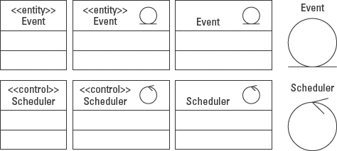
Figure 5-9: Four ways to model classes with stereotypes.
The two circular icons are alternative notations for entity and control stereotypes. The icons can be used with or in place of the stereotype labels. The icons may even be used by themselves, replacing the class rectangle symbol altogether.
These icons were absorbed from the Object-Oriented Software Engineering method by Jacobson, Christerson, Jonsson, and övergaard.
The following examples using the «utility» and «enumeration» stereotypes further illustrate the versatility and timesaving aspects of the stereotype concept for modeling systems.
Utility class
A utility class has no instances. Instead, it represents a named collection of static (class-scoped) attributes and operations. In other words, a utility acts a bit like a dictionary on your desk. There is only one copy and everyone references that one copy. A common use for utility classes is to hold common functionality used throughout the system. For example, the Math class in Figure 5-10 provides basic mathematical functions that could be used virtually anywhere in a system.

Figure 5-10: Utility classes have no instances and contain only static operations.
Enumeration
An enumeration is a user-defined datatype that defines a set of values that don't change (constants). Figure 5-11 shows the UML VisibilityKind enumeration used to define visibility throughout the UML specification. It defines the valid set of values for setting the scope of access on attributes, operations, and other model elements. Each entry is a literal, a static string of text like “public” that represents a valid option for some value.

Figure 5-11: An enumeration class defines a set of literal values, usually used for validation.
Properties
Below the name inside the name compartment, UML also allows you to add properties. Properties are simply pieces of information about the class that do not fit easily into one of the predefined compartments or elements. For example, you might want to add a “development status” to let team members know whether the class description is complete, under revision, finalized, and so on. You could also add audit details such as who last worked on the class, history of changes, and a version number.
 If there is a lot of this type of information about the class, you can also create a user-defined compartment to hold the properties. User-defined compartments are described fully in the “Modeling User-Defined Compartments” section later in this chapter.
Properties are expressed as a tag-definition/tagged-value pair, such as author=“Tom”, and enclosed in a single pair of braces ({}). If there are multiple properties, simply string them together, separated by commas, inside the same pair of braces.
Tagged values are described fully in Chapter 3.
Figure 5-12 adds the properties Author=“Tom”, Last_updated=“09-18-02”, and Approved to the Event class. Author, Last_updated, and Approved are tag definitions, names of properties. “Tom” and “09-18-02” are tag values associated with the tag names. The Approved property is a Boolean tagged value, which is expressed using the presence of the tag name to indicate true, and the absence of the tag name to indicate false. So the Approved tag in Figure 5-12 is visible to reflect a true value. The word Approved would not appear if the Boolean value were false.
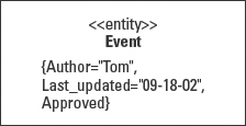
Figure 5-12: Examples of properties using tagged values.
UML 2.0
UML 2.0 has reorganized the definition of a class to align it more closely with the MOF. The UML 2.0 portions of this chapter step through the UML 2.0 specification identifying the key elements of the class definition and highlighting significant changes from UML 1.4. I use this same approach in each chapter on UML diagrams, and often for individual topics within a chapter.
If your goal is to learn the UML diagrams quickly so that you can get busy modeling, I recommend that you skip the UML 2.0 sections. The differences between the UML 1.4 and 2.0 notations are fairly straightforward, but the 2.0 sections provide a lot of specification detail that goes beyond the nuts and bolts of drawing the diagrams. Once you become familiar with the diagrams, the notations, and the vocabulary, then return to these sections and tackle them one at a time.
To give the following discourse a context, I'll quickly review the UML 2.0 architecture. (For an in-depth review of the architecture read Chapters 2 and 3.) UML 2.0 has two distinct layers, the Infrastructure and the Superstructure. The Infrastructure provides the foundation for all of the MDA components. The Superstructure defines the UML language and notation.
The Infrastructure is divided into four packages: Abstractions, Basic, Constructs, and PrimitiveTypes. Most of the elements used for modeling first appear in the Constructs package. But the Constructs package relies on the PrimitiveTypes, Abstractions, and Basic packages in much the same way that a book relies on rules of grammar and an alphabet.
The Superstructure relies on the essential concepts defined by the Infrastructure to build the concepts for constructing UML diagrams. The Superstructure is divided into packages for structural, behavioral, and supplemental diagrams. These three packages break down into packages for each UML diagram or concept, as in the Actions package. Each package provides a metamodel and definitions for each class in the metamodel.
In these UML 2.0 sections, I reference the packages within the Superstructure to review how classes are defined. As you walk through the Superstructure a few times, you will become increasingly familiar with the structure and the concepts. This particular UML 2.0 section covers only the concept of a class as a container for other model elements. Subsequent sections in this chapter will add attributes and operations.
The formal definition for a class in the UML glossary states that:
A class describes a set of objects that share the same specifications of features, constraints, and semantics. (UML 2.0)
This is a good working definition. But for modeling purposes this definition needs to be a bit more rigorous. The definition must work not only in conversation, but also for representing a class in a diagram. Classes are first defined in the Superstructure::Kernel ::Classes package (note the use of the fully qualified class name to describe the location of the class definition within the specification). In Figure 5-13, the hollow triangle on the end of the connecting lines is the UML inheritance symbol. So by looking over the diagram in Figure 5-13 we see that the class Class inherits from the class Classifier, which inherits features from Namespace, PackageableElement, and RedefinableElement.
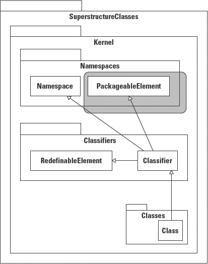
Figure 5-13: The ancestry of the definition for Class.
This definition is almost the same as in UML 1.4. But UML 2.0 adds the rule that a classifier may be a member of a package. While this was assumed in UML 1.4, it has been made explicit in UML 2.0. By inheriting from Classifier, Class incorporates a number of features already defined by other elements of the specification.
- As a subtype of Namespace, a class may contain NamedElements. Since a class is also a NamedElement, a class can be a member of another class. For example, a class may be declared within the scope of another class as are inner classes in Java.
- As a subtype of PackageableElement, a class may be a member of a package.
- As a subtype of RedefineableElement, a class may be specialized, just as Class specializes Classifier. For example, an AssociationClass inherits and specializes the features of both a class and an association to create a new type of model element for capturing information about a relationship. See Chapter 6 for a complete description of association classes.
In UML 1.4, some of the key features, attributes, operations, and associations that are generally associated with a class were actually defined for classifiers and then inherited by a class. In UML 2.0, these features are assigned directly to the class. Specifically, a class may possess structural features (attributes), and behavioral features (operations). Attributes and operations become owned features of a class in that they reside within (are encapsulated within), and travel with the class. Figure 5-14 illustrates this relationship using the lines (associations) connecting the Class icon to the Property and Operation icons. I'll explain the terms property and attribute in just a moment.
This chapter covers attributes and operation in the sections titled “Modeling the Attributes Compartment” and “Modeling the Operations Compartment”.
Figure 5-14 also states that a class can contain classifiers. In other words, a class can contain interfaces, associations, signals, enumerations and more. For a complete list of classifiers, see “Appendix E, Classifiers Taxonomy” in the UML 2.0 specification.
One significant structural change in the definition of a class is the addition of the concept of a Property. UML 1.4 used the Attribute class to define data owned by a class. But since data may be used to describe a variety of model elements other than classes, it made sense to define a concept, Property, that contains information, and then use that same concept wherever it is needed. When a property is owned by a class it is interpreted as an ownedAttribute (see Figure 5-14).
UML 2.0 does add a new concept called a Port, found in the Superstructure :: CompositeStructures :: Ports package, and illustrated in Figure 5-15. A port is both a ConnectableElement and a Feature. As a Feature, a port can become part of a class definition. As a ConnectableElement, a port provides the means to connect two elements of the model. Compare this idea of a port to something like airlocks on submarines or spacecraft. When two ships need to connect, they only need to know whether the airlocks on the two ships are compatible. How big the craft is or what technology or design is involved in each craft is completely irrelevant. If the connectors can attach properly, the ships can dock.

Figure 5-14: A class may contain nested classes, attributes, and operations.
©OMG 2.0 (modified)
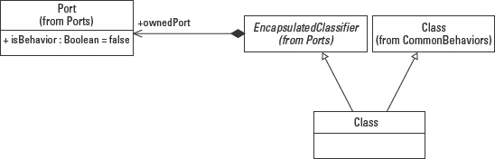
Figure 5-15: Adding ports to the class definition.
©OMG 2.0
In a similar manner, ports provide the “airlocks” to connect objects. A port is a class' gateway to the outside world. The addition of ports is an attempt to encapsulate a class from the technology in which it is implemented. By using ports, a modeler is able to create a class definition that may be implemented in any programming environment, as long as the connections conform to the definitions of the ports.
So whether one object is coded in Java and the other in C++ should not matter. Obviously, we are not quite there yet, but that is the goal of adding ports to the class definition, to create opportunities to reuse a software specification by rethinking how we define software requirements like connectivity.
The next section of this chapter continues the description of the UML 1.4 specification for classes. Each new topic in this chapter is followed by a description of UML 2.0 specification for the same subject area.
Modeling Visibility
Visibility is applied to both attributes and operations in a class. Since this concept applies equally to attributes and operations, I'll cover the concept here, and then demonstrate how to apply it in the descriptions of attributes and operations that follow.
Visibility refers to the scope of access allowed for a member of a class. Scope refers to specific regions within the total system. UML visibility or access levels map to similar visibility designations in most OO programming languages as follows:
- Private scope: Within a class
- Package scope: Within the same package
- Public scope: Within a system
- Protected scope: Within an inheritance tree
To understand visibility it is helpful to comprehend the concept of a UML namespace. A namespace is a UML element that can be named (inherits from NamedElement), and can contain other NamedElements. A UML class is a namespace that can contain NamedElements in the forms of attributes and operations. A package is a namespace that can contain classes and other packages. As namespaces, both classes and packages can control access to contained elements by assigning a visibility value.
As I explain each visibility in the following pages, note the symbols used to designate each visibility level, displayed in Table 5-2.
| Visibility Level | Symbol |
| Private | – |
| Package | ~ |
| Public | + |
| Protected | # |
As with most UML concepts, there is latitude in how you choose to represent visibility. The UML suggested character symbols for each visibility type are included in the following explanations. Some vendors have chosen to use colors or images, such as a closed padlock to identify private access.
Private visibility
UML definition: “A private element is only visible inside the namespace that owns it.” (UML 2.0)
In the context of classes, private (–) visibility limits access to objects of the same class. For example, private attributes of Class B in Figure 5-16 can only be accessed by operations performed by objects of Class B. They would not be accessible to Class A, other classes in the same package, or to any classes in Package 2, or elsewhere in the system. Contrast this with the other visibility values described later in this section.
If you adhere strictly to encapsulation, all attributes should use private visibility because all of the data that an object owns should be hidden within the object, accessible only through operations. The exceptions to this are inherited attributes that are covered by the protected visibility value (covered later in this section).
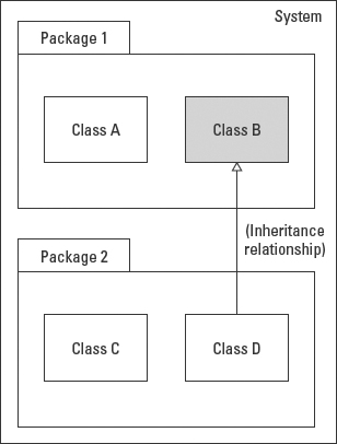
Figure 5-16: Private elements of Class B are visible/accessible only to objects of Class B.
Package visibility
UML Definition: “A package element is owned by a namespace that is not a package, and is visible to elements that are in the same package as its owning namespace.” (UML 2.0)
That is, package (~) visibility allows access by other objects in the same package, regardless of the class they belong to. For example, in Figure 5-17, let's say that Class B defines an operation with package visibility. Package visibility allows an operation in Class A, and objects of any other class in Package 1, to invoke the package-level operation in Class B. But the operation remains inaccessible to objects in Package 2, or any other part of the system.
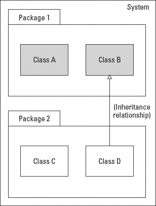
Figure 5-17: The package-visible elements of Class B are visible/accessible to all objects in Package 1.
Public visibility
UML Definition: “A public element is visible to all elements that can access the contents of the namespace that owns it.” (UML 2.0)
Public (+) visibility allows access by objects of all other classes in the defined namespace anywhere in the system. As Figure 5-18 shows, as long as an object can “see” the package that contains the public element (an attribute or operation), it can access that element.
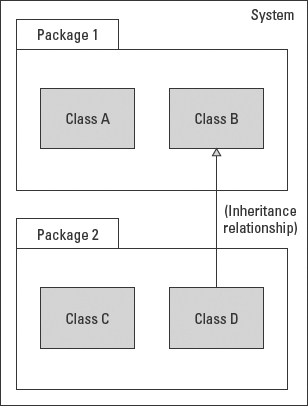
Figure 5-18: The public elements of Class B are visible/accessible to objects in the same system regardless of the package they reside in.
Protected visibility
UML Definition: “A protected element is visible to elements that have a generalization relationship to the namespace that owns it.” (UML 2.0)
Protected (#) visibility allows access by subclasses. In generalizations (inheritance), subclasses must have access to the attributes and operations of the superclass so that they can inherit these features. This is true whether or not the subclasses reside in the same package. For example, in Figure 5-19, objects of Class D are allowed access to the protected attributes and operations of Class B because Class D is a subclass (specialization) of Class B.
Check your programming language implementations for protected visibility because the definition varies across languages. For example, in Java protected also allows access by objects in the same package. The net effect of Java's implementation is a blend of package and subclass level visibility.
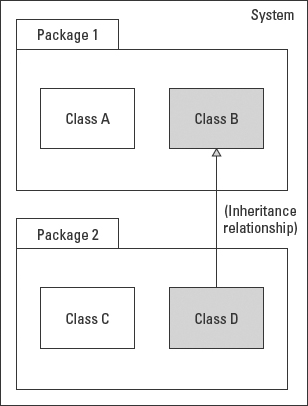
Figure 5-19: The protected elements of Class B are visible/accessible to subclasses of Class B regardless of where they reside.
In circumstances where a named element ends up with multiple visibilities, for example by being imported multiple times, public visibility overrides private visibility.
Protected access is especially valuable when you consider that a great deal of object-oriented programming is accomplished by extending existing libraries. For example, while writing an accounts receivable application, I might define an Account class that contains my customer's personal billing information. Later, while working on a marketing application, I am asked to enhance the system to handle different classifications of accounts for marketing purposes. To do so I need to specialize the Account class. But marketing and accounts receivable are in two different domains.
One solution is to make the features of the Account class public. But that means that any object in the system can access the features without using an operation that can validate the access. I could make the Account features private to prevent access but that would also prevent inheritance, since inheritance is a form of access. The only solution is a compromise. Allow access outside the class, but only to the classes that need to inherit from it.
To standardize these visibility definitions the UML 1.4 authors created a class called VisibilityKind. The VisibilityKind class pictured on the right in Figure 5-20 is a set of the valid values for visibility. In addition, UML 2.0 assigns a visibility to every NamedElement. So every model element that extends NamedElement, such as classes, attributes, and operations, has a visibility designation.

Figure 5-20: VisibilityKind and NamedElement classes.
©OMG 2.0
Modeling Multiplicity
Multiplicity, like visibility is a concept used with a number of UML model elements, most notably with attributes and associations. Multiplicity specifies the number of values that may be associated with a model element.
Multiplicity is modeled as a value expression. When multiplicity is used in a text string like an attribute, the value expression is enclosed within square brackets ([]). When multiplicity is used to adorn a diagram notation like an association, it has no enclosing brackets. Multiplicity can express a range of values, a specific value, a range without limit, or a set of discrete values.
Range of values
A range of values includes a lower and an upper value separated by two periods, as in [0..5] or 0..5, zero through five inclusively, and [6..10] or 6..10, six through 10 inclusively. Figure 5-21 represents an attribute called performer that may contain values for 1 to 20 performers.

Figure 5-21: Modeling a range for the number of values associated with an attribute.
Specific value
When the upper and lower values in a range are the same, the UML allows the use of the upper value by itself. So the multiplicity [2..2] can be displayed instead as [2], as shown in Figure 5-22 where the manager attribute can hold exactly two Venue_Manager references.
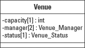
Figure 5-22: Using the upper value when the lower and upper range values are the same.
Note that while this abbreviated form is valid, you should be careful when replacing [1..1] with [1]. One of the most common errors in modeling is forgetting to ask whether the lower value should be zero. A lower value of zero as in [0..1] indicates that the item is optional. A lower value of 1 as in [1..1] or [1] indicates that the value is always present and required. In my experience the lower bound is zero the vast majority of the time.
Range without limit
When the upper value is unknown or unspecified, the UML uses the asterisk (*) in place of a number value. The asterisk appears as the upper value as in [1..*], which means one or more. The range [0..*] means zero or more. The asterisk by itself [*] also means zero or more. Figure 5-23 shows the price_tiers attribute set to one or more.
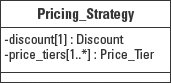
Figure 5-23: Use an asterisk to signify “or more,” meaning no upper limit.
Set of discrete values
In UML 1.4, a set of discrete values is separated by commas, as in [2,4,6]. To date, UML 2.0 submissions seem to have left out this option, but it will likely be included in the final version.
Ordering
UML also supports the option to specify the ordering of the elements counted by the multiplicity. The ordering is placed within curly braces ({}) after the multiplicity value, as shown in Figure 5-24. Ordering is actually defined as a Boolean property called is Ordered, so if the set of values is not ordered, the property is not shown.

Figure 5-24: Multiplicity ordering.
In the specification and other places you will also see {ordered}. Technically, a Boolean positive value is represented by the name of the Boolean tag, in this case, isOrdered. The other form appears to be a carryover from previous versions of the UML. Since most modeling is done using a tool, you will get whatever form the tool vendor decided to provide when you select the ordered option.
UML 2.0
The Superstructure :: Kernel::Multiplicities package defines a Multiplicity Element as having an optional lower value and an optional upper value, as well as two attributes, is Ordered and is Unique, pictured in Figure 5-25. The is Unique attribute is new in UML 2.0. Uniqueness in this instance refers to the values that the multiplicity refers to. For example, a multiplicity might be that there may be zero to 5 values associated with this attribute or association. A value of true (the default) for the attribute is Unique states that there are no duplicates in the set of values. A value of false for the attribute is Unique states that there can be duplicates in the set of values.
UML 2.0 specifies the following syntax for declaring the multiplicity for a model element:
multiplicity_range ::= [ lower ‘..’ ] upper
lower ::= integer | value_specification
upper ::= integer | ‘*’ | value_specification

Figure 5-25: Multiplicity associated with any TypeElement.
©OMG 2.0
The lower and upper values may be any value specification, including expressions, literals, and instance values (references to objects). The upper value is always required. The lower value is required when it is different from the upper value. When no specific upper value can be defined, the asterisk may be used to indicate that there is no upper limit to the value.
Along with the multiplicity values, multiplicity can designate the ordering and the uniqueness of the values in the set bounded by the multiplicity values. The syntax for ordering and uniqueness is as follows:
[ ‘{’ <order_designator> [, <uniqueness_designator>]‘}’ ]
<order_designator> ::= ordered | unordered
<uniqueness_designator> ::= unique | nonunique
The isOrdered attribute is a Boolean value used in conjunction with a multi-valued multiplicity. It specifies whether the values in an instantiation of this element are sequentially ordered. The default value is false.
The isUnique attribute is a Boolean value used in conjunction with a multi-valued multiplicity. It specifies whether the values in an instantiation of this element are unique. The default value is true.
The isOrdered and isUnique attributes are modeled as properties inside curly brackets ({ }). Figure 5-26 illustrates the use of both ordering and uniqueness where both values are true. In an attribute declaration these properties follow immediately after the multiplicity value.
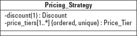
Figure 5-26: Modeling ordering and uniqueness with multiplicity.
The isUnique and isOrdered attributes describe the structure of a collection. For example, the multiplicity can describe a set of values for an attribute or a set of references in an association. The implementations for these sets must conform to the rules for the set defined by the values of isUnique and isOrdered. The unique combinations of these two attributes define the types of collections that may be used to implement the sets following the rules illustrated in Table 5-3. The exact implementation mechanism for the collection will depend on the resources available through the implementing programming language.
Table 5-3 The use of properties for Collection types

Modeling the attributes compartment
The attributes compartment contains definitions for all the information that an object owns. Like the other compartments, it is simply a list of like items, a list compartment. It differs from other compartments in two ways. It may only contain attributes and it always appears in the same relative location within the class icon, just below the name compartment. The attribute compartment contains all the information that an object can own.
Modeling an Attribute
An object can own three types of information. First, an object must know about itself, namely its own structure and its own current condition, called its state. Second, an object is aware of its immediate relationships. Third, an object is sometimes made responsible for overseeing specific information, much like a steward or custodian.
An object can tell you about itself. In Figure 5-27, Venue can tell you its seating capacity and its current status, that is, open, closed for holiday, closed for repairs, or reserved for private engagement. Event can tell you its start and end dates, the number of shows that have been scheduled so far for the event, the number of shows that the contract states may be scheduled, and its current status, that is, tentative, contracted but not scheduled, scheduled, completed, or cancelled. Seat can tell you its location within the venue and its current condition (disabled or available for use).
In order for an object to do work, it typically needs to interact with other objects. To do so, a class must define the valid set of relationships and the rules for establishing and breaking those relationships. For example, when a project team is first established, the members are assigned tasks. Often those tasks are interrelated. Members of the team record the contact information of other members, like phone numbers and e-mail addresses, so that they can collaborate.
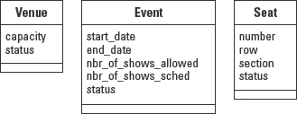
Figure 5-27: What an object knows about itself.
Likewise, classes need to define a means for each object to contact other objects so that they can collaborate. The class defines an attribute that can contain a reference to another object. Each type of reference requires a different attribute. Keeping with the team member example, a developer might keep references for a project leader and for a database administrator. Each attribute points to an employee, but each attribute refers to an employee for a unique purpose.
Alternatively, a reference may be to a collection of objects, all for the same reason. For example, a member of the team may keep a reference to the list of fellow team members. In this case, a single attribute holds multiple references. In UML, this is modeled using multiplicity. In a programming language, this is accomplished with an array or some type of container class like a Java Collection, such as a Vector.
Today most modeling tools provide some help for setting up these reference attributes. They do it based on associations (discussed in Chapter 6). For example, when an event is scheduled at a venue, the event needs to know where it will be held. In a manual system, the manager might write the venue name on the contract for the event. In a similar manner, the Event class needs to include a place to “write” the reference to the venue so that it can collaborate with the venue to set up the performances. For each relationship on the class diagram, the modeler (or the modeling tool) must generate a reference attribute like the one shown in Figure 5-28.
An object can also own information that the object is not directly responsible for either creating or maintaining. For example, a System Event Log has to track error conditions encountered during the execution of the system. The log does not generate these system events or have any control over them. It simply provides a place to record them.

Figure 5-28: Add the reference attribute so that the event can collaborate with the venue.
Regardless of the type of attribute, each attribute needs to be defined to the level at which the application can insure the integrity of the attribute and of the system in which it is used. To accomplish this, a UML attribute definition includes the following elements:
- Visibility
- Derived (true/false)
- Name
- Data type
- Multiplicity
- Default value
- Property string
- Class-level versus instance level designation
Attribute notation
These attribute definition elements are commonly expressed in a single text string using the following syntax:
[visibility] [/] name [: type] [multiplicity] [=default]
[{property-string}]
The attribute definition string is a handy way to document the features of an attribute. However, tools typically also offer a form containing a separate field for each feature. Using this form, the tools can offer help in the form of drop-down lists and defaults to ease and speed up the modeling process. Figure 5-29 shows an attribute definition screen from MagicDraw 6.0.
Software only works if it has all the information it needs. By definition, all the information in an object-oriented system is contained within objects as attributes. The elements of an attribute definition help insure that all of the facts have been evaluated and explained. The rest of this section defines and describes the use of each of these elements.

Figure 5-29: Sample attribute-entry form in a modeling tool.
©No Magic
Visibility
[visibility] [/] name [: type] [multiplicity] [= default] [{ property-string }]
Earlier in this chapter I explained the various levels of visibility. I also reinforced the concept that encapsulation states that all of the attributes of an object should be private. Figure 5-30 models seven attributes for an event. All the attributes are set to private using the minus sign symbol (–) in front of the attribute name.

Figure 5-30: Assigning private visibility (–) to attributes to enforce encapsulation.
In the initial stages of analysis, it is usually easiest to simply default all attributes to private (–) visibility. Later, if you find a compelling reason to change it you can always do so.
Derived
[visibility] [/] name [: type] [multiplicity] [= default] [{ property-string }]
A slash (/) in front of an attribute name identifies the attribute as containing a derived value. The absence of the slash indicates a base value. A derived value is one that's computed, or figured out, using other data and a rule or formula. A base value must be provided because there is no other way to obtain the value. When an attribute is determined to be derived, there are more design decisions that need to be addressed regarding the handling of the data, so the derived flag is used as a reminder to the modeler until there is time to resolve the handling of the data. Base values are designated by the absence of the derived symbol.
For example, a theater employee might need to create a report detailing events that are scheduled. The report needs to provide the name of each event as well as the start and end dates of the events. The name attribute defines a base value because the name cannot be calculated or figured out by any rules. It must be provided by a user. The start_date is also a base value. The end_date however, can be calculated using the event duration and the start date. So in Figure 5-31, a slash is placed after the visibility symbol and before the attribute name to indicate that end_date represents a derived value.

Figure 5-31: Identifying base and derived attributes.
Depending on factors like frequency of access and cost to calculate the derived value, you might choose not to store the end_date value at all because you can calculate it at a lower cost than storing it.
In some cases, the calculation is very costly, access is frequent, and timeliness is critical, while the values don't change very often or not at all. Then it might very well be cheaper to store the derived value than to calculate it every time it is needed. For example, I worked with a team responsible for distilling all of the weather data from NASA weather satellites each day. The distillations were then distributed to universities and researchers around the country. The data shipped was derived from more than a terabyte of raw data. The team had to define a derivation strategy for virtually every attribute of the final product. When it was finished, the derived values had to be stored and the raw data erased.
Use the slash (derived) symbol to remind you that more work needs to be done to decide on the handling of the derived value. Once a decision is made, you can always delete the attribute if it is not stored and use only a corresponding operation to calculate it when needed.
Name
[visibility] [/] name [: type] [multiplicity] [= default] [{ property-string }]
The attribute name is required. The name must be unique within the class. Attribute names should be as descriptive as possible to avoid confusion. Names are one place where brevity is not a virtue. Always remember that other people may need to read and understand your code long after you are gone. Frankly, even while you are still around, do you really want to be hounded with questions about cryptic names?
If the same name appears in multiple classes and you need to refer to both values in the same context, the attribute name must be qualified with the class name in the form class_name.attribute_name. For example, when the attribute status appears in both Venue and Event you would need to specify them as Venue.status and Event.status, respectively.
Data type
[visibility] [/] name [: type] [multiplicity] [= default] [{ property-string }]
An attribute type identifies a classifier (not class) that explains the kind of information that can be stored in the attribute. A classifier may be:
- A reference to a UML primitive Data Type (Integer, UnlimitedInteger, or String)
- An enumeration such as Boolean
- A reference to a language-specific type such as float, long, short in Java
- A reference to another class in your system
For example, in Figure 5-32 the name attribute is assigned the UML Data Type String using the format name : String. End_date is assigned a class called Date from a library of classes provided by the Java programming language. The Date data type actually holds a reference to an object designed to represent information about a date and time. status is assigned a reference to an application-specific enumeration called Event_Status, which defines a set of valid literal values for event status, such as scheduled and cancelled.
The UML attribute definition only allows for one data type. But remember that system development is a series of tasks encompassing gathering requirements and converting those requirements to a solution. During requirements gathering, the data type should reflect how the client sees the data, such as dollar signs and commas, and parentheses for negative values—($12,345.67), for example. You could call this the external view, the way the values look outside of the software application. During design, however, the data type needs to correspond to the programming language and database data types for the environment in which the class will be coded, such as float. This is the internal view, the way the information looks inside the software application. These two different views of the required data type can give the programmer some very specific insights for coding the operations used to capture and retrieve the attribute value/s.

Figure 5-32: Each attribute is assigned a data type.
The external view identifies the form that the value takes as input and output. The design-level definition defines the internal storage requirements. The accessor methods, the operations used to put the data into the object and take it back out of the object, are responsible for the translation between the two forms. In some instances there may even be many external forms, as in Figure 5-33. The Ticket class defines an internal data type of float, to match the desired programming language type, to contain a price value. But the clients want to use the value of the price attribute in three different formats.
So during requirements gathering, the data type captured in the attribute definition should reflect the clients' expectations, external view. The design-level version of the model should replace the external view with the internal representation. This is one reason the version control is so important for the modeling process.
Multiplicity
[visibility] [/] name [: type] [multiplicity] [= default] [{ property-string }]
When an attribute may have only one value, you can use a multiplicity range of [1..1], the abbreviated form [1], or even let the attribute assume a default multiplicity of 1. In Figure 5-34, I used the [1] notation, although it is very common to use the default. An attribute may also contain more than one value. Referring to the multiplicity notation defined earlier in this chapter, you can express, for example, that a venue contains references to two managers, a primary and an alternate. The venue could define a manager attribute as either manager : Venue_Manager [2] or manager [2] : Venue_Manager. The multiplicity expression may appear by the attribute name or the data type. Technically it just needs to be somewhere in the attribute definition text string. These expressions tell us that the attribute called “manager” is of data type “Manager” (a reference to a Manager object), and that the attribute may contain two [2] references.
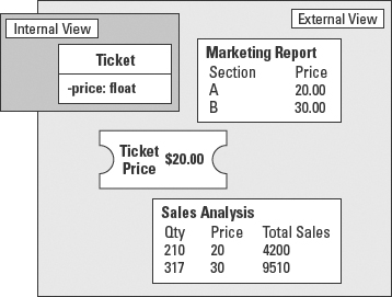
Figure 5-33: Internal and external data types.
As I mentioned earlier, when an attribute contains multiple values it is usually implemented with some type of array or container class reference. For modeling purposes, however, it can be handy to simply capture the requirement that the reference needs to support a set of values, not just one. Once you are certain that the attribute is defined correctly, you can resolve the design alternatives for handling the set of values.
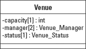
Figure 5-34: Attribute multiplicity.
Default value
[visibility] [/] name [: type] [multiplicity] [= default] [{ property-string }]
Default values serve two very valuable purposes:
- To protect the integrity of the system from being corrupted by missing or invalid values.
- To provide significant ease-of-use improvements for the client.
For example, it is common practice to let the programming language syntax default numeric attributes to zero. However, if the application ever attempts to divide using one of these values, you will have to handle the resulting errors that could have been avoided easily with the use of an explicitly specified default value.
UML adds the default value to the attribute definition string using an assignment operator (=) followed by the default value expression. The default value expression may be a single value or a string expressed in some language like the Object Constraint Language or an implementation language. During modeling it can work equally well to use free-form text in the default to capture what you want to do. Then return later to iron out the specific language. However, UML does not provide any mechanism for resolving the expression language. So it is up to the designer to provide the code to implement the rule defined in the default expression.
Default values are applied to the attribute when an object is created. They may appear in the constructor as hard-coded values. They may be defined as class-level or static values that can be referenced in the constructor. They may even be stored elsewhere and loaded using a static operation when the class is loaded. The concept of static attributes is covered a little later in this same section. (The static concept applies to operations as well.)
In Figure 5-35 default values have been added to the Event attributes following the assignment operator (=). The descriptions follow the figure.

Figure 5-35: A default value assigned to each attribute can help prevent errors and improve ease of use for your clients.
- name and start_date: There are no default values, but a value is required for both attributes. This combination tells us that the value must be supplied (no default) and it must be supplied immediately when an event object is created (required). Consequently, it must be an input parameter on the constructor (operation) that creates the object.
- end_date: end_date is a derived value so the default expression describes how to derive the value. (Technically, it could also simply refer to the properties value covered next in this chapter.)
- duration_in_days, nbr_of_shows_allowed, and nbr_of_shows_sched: All three attributes default to a value of 1.
- status: The event status defaults to the Scheduled value defined by the Event_Status enumeration.
- venue: The venue reference defaults to whatever the primary venue is at the time. The default here is expressed in freeform text, assuming that the designer can find a way to determine the primary Venue and insert that logic into the Event to set this value.
To recap, a default expression may be a value or a String expressed in some language. This is one more place where the Object Constraints Language may be used to formalize an expression. In fact, the expression “Event.status” is actually a very simple OCL statement.
Property string
[visibility] [/] name [: type] [multiplicity] [= default] [{ property-string }]
The property string is like a catchall for anything you might want to include in the definition but for which there is no designated location. The most common use of the property string is to express the rules required to guarantee the integrity of the attribute value whenever another object attempts to change it. Any time another object tries to alter the attribute value, it must pass the rules established in the property string. These rules may be expressed as constraints on the value and may even use the Object Constraint Language (OCL) defined by UML and covered in Chapter 18. The constraints are implemented/enforced in any method that attempts to change the attribute value.
Figure 5-36 models the Event class with the properties added to the end of each attribute definition string, enclosed in a pair of braces ({}). Properties may be expressed as free form text, a standardized language, or tagged values. Multiple properties are separated by commas.
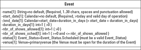
Figure 5-36: Attribute properties enable you to define constraints and other facts to ensure the integrity of the attribute value.
In Figure 5-36, the following properties are added to the Event attributes:
- name: The name value must be 1 to 30 characters long. It may include spaces and punctuation (but no other special characters).
- start_date: The start date value must be later than today, that is, the system will not allow retroactive event setups. We must also make certain that the venue is actually open when the event starts. This reveals one of the benefits of researching the properties and constraints for an attribute. The research often exposes the need for other information. In this case, the constraint on the start_date reveals the need for a calendar of operation that identifies when the venue is open for operation.
- end_date: Since the end_date is a derived attribute, the constraint is the same as the default. That is, they are both the rule for deriving the value.
- duration_in_days and nbr_of_shows_allowed: Both attributes simply need to have a non-zero value, although you might want to find out whether there is a reasonable limit to either value.
- nbr_of_shows_sched: This attribute must conform to the limitation established by nbr_of_shows_allowed. nbr_of_shows_allowed is established in the contract with the performer and cannot be exceeded without revising the contract. The lower limit is zero to allow for the fact that when the event is entered into the system you might not yet know when you want to schedule the shows. The zero lower limit enables you to set up the event, go home for the evening, and come back the next day to do the scheduling.
- status: The valid set of status values have been defined within a class called Event_Status. The status attribute may only refer to one of the predefined values.
- venue: It would not make much sense to schedule the event to take place in a venue that will not be open. This constraint helps the clients make certain that everything is ready before they start scheduling.
To recap, properties enable you to define any information about the attribute that does not fit into one of the predefined fields for an attribute. The most common use of properties is to hold the constraints that guarantee the integrity of the attribute value throughout the object's lifetime.
Class-level attribute
Most attribute values are owned by a specific object, an instance of a class. They are called instance-level attributes. A class-level attribute refers to an attribute that is accessible within the class. Class-level attributes are also referred to as static attributes in some languages. Because the value is defined and stored at the class level, every object of the class may access the value. Literally, all of the objects of the same type share the same value.
One example of the use of a static attribute is the ticket in the theater application. The ticket class needs to sequentially number the ticket objects to ensure that there are no duplicates. The ticket class could define a static attribute next_ticket_nbr as shown in Figure 5-37. Each time a ticket object is created, the value in next_ticket_nbr is assigned to the ticket's ticket_nbr attribute. Then the next_ticket_nbr is incremented on the ticket class.

Figure 5-37: A static attribute is modeled by underlining the attribute definition.
UML 1.4 stated that a static or class scoped attribute is designated by underlining the entire definition text string, for example: next_invoice_nbr : int = 1.
As of this writing, UML 2.0 does not explicitly say that a static attribute is underlined. However, it does define all features, such as attributes, as having a Boolean attribute called isStatic. This would allow you to define an attribute as static. The notation will probably be updated in the final version.
UML 2.0
This section reviews the UML 2.0 specification for any changes, enhancements, or clarifications with regard to defining attributes. Apart from the name change from Attribute to Property, most of the changes regarding attributes are changes to the structure of the metamodel. Figure 5-38 summarizes the metamodel elements that affect the definition of a property. The highlighted areas indicate the sources of the information that defines a property.

Figure 5-38: A property inherits many of its features from other metaclasses.
©OMG 2.0
That information includes all the items in the attribute declaration syntax:
[visibility] [/] name [: type] [multiplicity] [=default]
[{property-string}]
- visibility (from NamedElement): As a subclass of NamedElement, a property inherits both name and visibility. The valid options for specifying visibility are defined by the enumeration called VisibilityKind.
- derived (/): (See Figure 5-39 and the subsequent description.)
- name (from NamedElement): As a subclass of NamedElement, a property inherits both name and visibility.
- Type (from TypedElement): As a subclass of TypedElement, a property inherits an association with a classifier that provides its type. That is, a property may be a UML DataType (Primitive or Enumeration), a class, signal, or any other classifier or subclass of classifier.
- multiplicity (from MultiplicityElement): As a subclass of MultiplicityElement, a property may own an upper and a lower limit for the number of values that may be contained in the property.
- default (/): (See Figure 5-39 and the subsequent description.)
- property-string (from Element): As a subclass of Element, a property may own other elements. These other elements may be used to augment the description of the property. The most common additional element is a constraint or set of constraints on the domain of values for the property.
- isStatic (from Feature): As a subclass of Feature, a property owns the attribute isStatic. If isStatic is true, then the property applies to the classifier that owns the property, not to instances associated with the classifier. The default value is false. The attribute was formerly defined by the enumeration ScopeKind, which included the values instance and classifier.
- isReadOnly (from StructuredFeature): As a subclass of StructuredFeature, a property owns the attribute isReadOnly. If isReadOnly is true, then the property may only be read, not written/changed. Once the property value is set it may not be changed. This feature was formerly defined by the enumeration Changeable Kind, which included the values changeable, frozen, and add Only.
In addition to the features already identified, a property may define whether it is derived, whether the values of the property is the union of other values, and how the property is associated with the classifier that owns it. Figure 5-39 introduces the property class itself with three new features, is Derived, is Derived Union, and aggregation, as well as an optional association with a value specification, and other properties that subset the property.
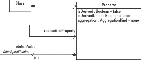
Figure 5-39: A property describes a class, may be subsetted, and may have a default value.
©OMG 2.0
- isDerived: Specifies whether the property's value or values can be computed from other information. The default value is false. The slash (/) in front of the attribute name designates that the attribute's value is derived from other properties. The absence of the slash designates that the attribute represents a base value.
- isDerivedUnion: Specifies whether the property is derived as the combination of all of the properties that defined subsets of the property. For example, in the class Company the model might define an attribute, employees. It might also define two other attributes, full-timeEmployees and part-timeEmployees. A true value for the isDerivedUnion attribute of the employees property defines the value of the employees attribute to be the combination of all the values of full-timeEmployees and part-timeEmployees. The default value is false.
- aggregation: Specifies the kind of aggregation that applies to the property, that is, none, aggregation, or composition. The default value is none. The kinds of aggregation are explained fully in Chapter 6.
- default: A property can be associated with a value, defined by a ValueSpecification. This value is assigned to the property if no explicit assignment is made at the time that the property is created. In the case of a property that represents an attribute of a class, the default value is assigned to the property when an instance of the classis created.
- subsettedProperty: This association points to other properties for which the source property defines a subset. In the example described under the isDerivedUnion attribute, the property full-timeEmployees would point to the property employees. (See the example that follows the next paragraph.)
The isDerivedUnion and subsettedProperties attributes may be added to the attribute declaration string using the optional {property-string}. Each feature added to the property string is a separate tagged value in the property string. For example:
full-timeEmployee : Vector = null {union, subsets employee}
Modeling the operations compartment
The operations compartment is a list-compartment containing all of the behaviors defined for a class of objects. The default location of the operations compartment is below the attributes compartment and above any user-defined compartments. The compartment may be suppressed. Often, modeling tools also allow suppression of specific elements of the operation declarations within the compartment.
Within the operations compartment, it is valid to use stereotypes to label groups of operations according to their usage (or whatever criteria are useful to the maintenance of the class). The stereotype applies to all operations below it in the list until another stereotype appears or until you reach the end of the compartment, as shown in Figure 5-40.
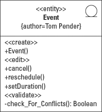
Figure 5-40: Operations compartment with stereotypes.
In all the figures in this section, the attributes compartment has been suppressed to keep the focus on the discussion of operations.
Modeling operations
Operations define behaviors, the services that an object can provide. UML makes a distinction between the interface to a behavior and the implementation of a behavior. The interface to a behavior is called an operation. An operation declares the information needed to invoke a behavior. The operation is the only part of a behavior modeled in the Class diagram.
The implementation, which is not modeled in the Class diagram, is referred to as the method. This can be a source of confusion because many programming languages use the terms operation and method interchangeably.
Operation notation
The UML operation notation defines the elements of a class behavior modeled using the syntax:
[visibility] name ([parameter-list]) ‘:’ [return-result]
[{properties}]
In addition, UML supports the use of exceptions, pre-conditions, and post-conditions. I'll cover the notation elements first, and then these additional operation elements.
Visibility
[Visibility] name ([parameter-list]) : [return-result] [{properties}]
Operation visibility follows the same visibility concepts covered earlier in this chapter. In the context of operations, visibility applies as follows:
- private (–): Only objects of the same class may call/invoke a private operation.
- package (~): Only objects owned by the same package may call a package-level operation.
- public (+): Any object may call a public operation, as long as the calling object can access the package in which the operation resides.
- protected (#): Only objects defined within subclasses of the owning class may call a protected operation.
Name
[Visibility] name ([parameter-list]) : [return-result] [{properties}]
The name of an operation identifies a specific behavioral feature of a class of objects. To be effective, the name should be as meaningful and expressive as possible. For example, an operation named update with a long string of parameters would be more difficult to interpret properly than operations named reschedule, addPerformance, or cancel.
The name does not have to be unique within a class. However, the combination of the name, parameter list, and return result, often called the signature, must be unique within the class. (Note that this rule is not the same for all programming languages. Some languages do not consider the return result to be part of the signature.)
Figure 5-41 contains operation names for the Event class. Each operation definition in the figure includes the operation visibility, an operation name, and an empty parameter list. Each operation models a behavior that an event object supports. The listed behaviors enable us to cancel the event, reschedule the event to a new time period, or change the duration of the event. I'll explain the Event and check_For_Conflicts operations in a moment.
Also, remember that the operations in the Class diagram will generate the operation code in your target language, so be certain to follow the naming standards for the target language because the code will be generated exactly as it is written in the diagram. For example, constructors are typically identified by the fact that the operation name is the same as the class name, like the Event() operation in Figure 5-41.
Note the visibility designations in front of each operation. Whenever a class needs to make a behavior available to other types of objects, the visibility cannot be private. Often the visibility is set to public until and unless there is a compelling reason to limit it to package, protected, or private.

Figure 5-41: Each operation identifies a behavioral feature of the class.
When a class behavior is only used internally, the visibility may be private or protected. Internal behaviors may be functions shared by more than one class behavior. For example, the event needs to check for scheduling conflicts when it is created and whenever someone tries to change its duration or start date. Rather than define the behavior twice, once within each operation, it is easier to isolate the behavior in its own operation and call it from the other two. Figure 5-41 models the check_For_Conflicts operation as private to restrict access to operations within the same class.
Parameter-list
[Visibility] name ([parameter-list]) : [return-result] [{properties}]
The parameter-list is an ordered list of attributes that together define the input to an operation. The parameter-list is optional, that is, an operation does not have to have parameters. For example, if I ask an event object to cancel itself using the cancel() operation in Figure 5-42, it does not require any additional information. It can satisfy the request with the knowledge it already has. However, to change the duration of the event, I have to tell the event what the new duration value should be. I do this by adding a parameter that can hold the new value in the parameter-list of the operation. Now when I invoke the operation, I can assign a new duration value to the parameter value and pass the parameter along with the request. The event object receives the parameter and uses the value to complete the operation.
In Figure 5-42, parameters are added to two of the operations. The reschedule() operation needs to know the new date on which you want to schedule the event. This new date will replace the current value for the attribute start_date. The setDuration() operation needs to know the new duration value that will be used to replace the existing value in the duration_in_days attribute.
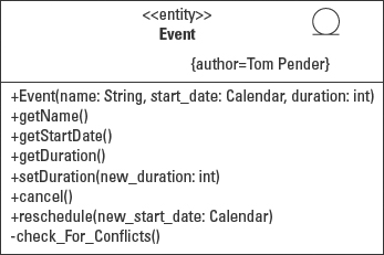
Figure 5-42: Operation parameters define the required input for the class behavior.
Each parameter is defined in the same manner used to define attributes, a name and a data type in the format name:datatype. When using more than one parameter, simply separate the “name : datatype” pairs with commas, for example (new_start_date : Date, new_duration : int).
 If you are a Java programmer, don't let the name:datatype syntax throw you. It is the opposite of what you are used to, namely datatype name, but it accomplishes the same purpose.
When an operation does not require parameters you still need to include the empty parentheses. Again this is largely because the operation definition will be used to generate code and needs the correct syntax.
Return-result
[Visibility] name ([parameter-list]) : [return-result] [{properties}]
The return-result is the output of the operation. For example, when I ask the event for its name, I want it to give me a string containing the name of the event, like the getName() operation in Figure 5-43. When I ask for the duration, I want the event to return an integer as in the getDuration() operation.
Note how different the return is from the parameters. The return specifies only the return data type. No name is required. Also note that there is only one return, whereas there are potentially many parameters. Technically, UML 2.0 supports many return values. However, most if not all programming languages support only one return value. If you need to return more than one result value, you will need to wrap the values up in another object and ship the entire object back as a reference.
It is valid to have no return value. But again, your programming language might require you to say so by using a keyword like void in the return.

Figure 5-43: Operation return-results define the output of an operation.
The return value may be any primitive type or object (or object reference). The getDuration() operation in Figure 5-43 returns a primitive integer value. The getStartDate() operation returns a Date object.
Properties
[Visibility] name ([parameter-list]) : [return-result] [{properties}]
The properties element allows you to add pretty much any additional information about the operation that does not fit into one of the other predefined elements. One common use for the properties is as a description of the implementation for the operation, as shown in the following syntax for an operation declaration:
setDuration(new_duration: int): void {the new duration may
not cause overlap with another scheduled event}
The property text describes the constraints on the performance of the operation. This is yet another occasion when the Object Constraint Language (OCL) might be applied to lend precision to the specification. Since properties may be defined with any language, not just OCL, it is valid to use free-form text. Ultimately the contents of the properties become part or all the implementation logic for the behavior.
Class-level operation
Most operations are owned by a specific object, an instance of a class. They are called instance-level operations. In contrast, a class-level operation refers to an operation that is accessible within the class rather than within an object of the class. Class-level operations are also referred to as static operations in some languages. Because the operation is defined and stored at the class level, every object of the class may access the operation. In fact, objects of other classes may access the operation without referring to an instance of the class.
One example of the use of a static operation from the theater system is the operation getNextTicketNbr():int, which returns the value of the next_ticket_nbr attribute, which also happens to be defined as static. UML 1.4 states that a static or class scoped operation is designated by underlining the entire definition text string, as illustrated in Figure 5-44.
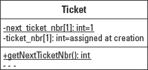
Figure 5-44: A static operation is modeled by underlining the operation definition.
As of this writing UML 2.0 does not explicitly say that a static operation is underlined. However, it does define all features, such as operations, as having a Boolean attribute called is Static. This attribute enables you to define an operation as static. The notation will probably be updated in the final version.
Exceptions
Those of you with a programming background might be asking, “What about exceptions?” One way to handle exceptions is to return a value to the calling object and let it interpret that value to decide how to respond to success or failure. The more common approach implemented by most OO languages is to throw (generate) an exception. An exception in this technique is an object. Exception objects may be specialized into almost any form to handle any type of error. Some languages even come with a predefined set of standard error types.
When a method throws an exception, that method is terminated and each successive method in the call stack is terminated until the exception is caught by an exception-handling code block. That code, specifically designed to capture exception objects, may then be enhanced to interrogate the exception object and decide how to respond.
The advantage to this approach is that it isolates error handling from the normal execution of the behavior that generated the exception. This separation makes the code easier to understand and maintain. It also helps make the error handling more reusable since all exceptions of the same type can be handled by common logic.
UML 1.4 does not have a notation for exceptions. It does, however, support the definition of exceptions as a type of signal that can be passed between objects. To provide the exception information you need to use the specification window provided by your modeling tool. Figure 5-45 shows portions of the screens used in MagicDraw 6.0 to specify exceptions in Java and C++.

Figure 5-45: Tools support the definition of operation exceptions.
©No Magic
Preconditions
The term precondition is borrowed from the concept programming by contract. In a conventional contract, one party agrees to do something or provide something if and only if the other party fulfills his part of the contract. For example, I will give you a pair of shoes if you give me $50. If you come to me with $40 I am not obligated to give you the shoes.
In the same manner, an operation may specify a precondition or a set of preconditions. The preconditions define the terms that the invoking object must meet before the operation is obligated to perform its behavior. A common example of this type of agreement can be seen in the use of parameters. An operation specifies that certain parameters must be supplied. It may further specify constraints on the values of those parameters.
Testing of the preconditions is the first task of the invoked behavior. Keeping with the previous example, if any parameter is not supplied or the value for any of the parameters does not satisfy the associated constraints, the operation is not obligated to perform its behavior.
This concept is also applied to Use Cases.
As was the case with exceptions, the preconditions are typically captured in a form provided by a modeling tool. There is no corresponding notation.
Post conditions
Post conditions also come from the concept of programming by contract. As the prefix implies however, the condition specifies something that must be true after the behavior finishes. Post conditions provide the other half of the contract, the obligation of the invoked behavior.
To keep with the precondition example, if you give me $50 (satisfy the precondition) then I am obligated to give you the shoes to satisfy the post condition.
In short, a post condition is a condition that must be true at the conclusion of the behavior. The process to satisfy the post condition is implemented in the method of the operation. The method can be as simple as a request and a response, as shown in Table 5-4, or as complicated as the example illustrated in Table 5-5:
Table 5-4 Pre- and Post conditions in a Simple Request/Response
| Step | Action |
| Request | “What is the event name?” |
| Precondition | None |
| Processing | Get the value of the event name attribute |
| Post condition | The event name: “The Sound of Music” |
Table 5-5 Pre- and Post conditions in a Complex Request/Response
| Step | Action |
| Request | “How much is the car insurance premium?” |
| Precondition | Provide the make, model, year, and mileage, options included, and driving record of drivers. |
| Processing | Calculate the car insurance premium using the current state mandated factors (15), historical factors (7), manufacturers' repair costs, actuarial tables for drivers in our state … |
| Post condition | “The car insurance premium will be $215.00 per month.” |
In both cases the pre- and post conditions set the boundaries that define the successful fulfillment of the operation. In a very real sense the preconditions and post conditions encapsulate the operation, defining its correct function without dictating any particular implementation.
The method does not appear in a UML diagram, although the logic can be modeled using an Activity diagram. Most modeling tools provide a comment or description area in the specification forms. Whatever is entered here–freeform text, pseudo-code, or actual code–can be generated as a comment in the code generated from the Class diagram.
UML 2.0
As was the case with attributes, the changes in the specification regarding operations are largely refinements to the metamodel. Figure 5-46 brings together all the classes that contribute to the features of an operation. Many of them you already encountered in the description of the UML 2.0 model for attributes, including NamedElement, MultiplicityElement, and Feature. The highlighted areas indicate the sources of the information that defines a property.

Figure 5-46: UML operation metamodel, part 1 of 2.
©OMG 2.0
The information used to define an operation is specified in the operation declaration syntax:
[visibility] name ([parameter-list]) ‘:’ [return-result]
[{properties}]
parameter-list:= name [‘:’ data-type ] [‘[’ multiplicity ‘]’]
- visibility (from NamedElement): As a subclass of NamedElement, an operation inherits both name and visibility. The valid options for specifying visibility are defined by the enumeration called VisibilityKind.
- name (from NamedElement): As a subclass of NamedElement, a property inherits both name and visibility. Name is simply a String. The combination of the name, parameter-list, and return-result must be unique within a class.
- parameter-list: A parameter may define information passed into and out of an operation. An operation may use any number of input parameters and may produce any number of output parameters. Though not supported by all programming languages, UML offers parameter direction types of in, out, inout, and return. These options are defined by the enumeration ParameterDirectionKind.
- name (from NamedElement): As a subclass of NamedElement, a property inherits both name and visibility.
- data-type (from TypeElement): Each parameter obtains its type from a classifier. For example, in order to define a parameter that can pass in a list of show seats, I need to associate the parameter with a classifier designed to contain a set of objects such as the Vector class in Java. The operation would look like select (showseats:Vector).
- multiplicity (from MultiplicityElement): As a subclass of MultiplicityElement, a parameter may own an upper and a lower limit for the number of values that may be contained in the parameter. For example, a parameter can contain a set of one or more show seats that a customer wants to purchase. The operation would look like select (showseats:Vector [1..10]).
- return-result: Each operation may return one or more values. Each value is a parameter, so each value is associated with a data type and a multiplicity. Technically, a parameter can have a name as well. But most programming languages specify a return using only the data type.
UML supports multiple return results. But many programming languages limit an operation return to a single value. During analysis determine what the operation needs to return. During design you can combine multiple values into an object and pass the one object as the return.
- properties(from Element): As a subclass of Element, a property may own other elements. These other elements may be used to augment the description of the operation. The most common additional element is a constraint or set of constraints on the behavior of the operation.
- isStatic (from Feature): As a subclass of Feature, a property owns the attribute isStatic. If isStatic is true, then the property applies to the classifier that owns the property, not to instances associated with the classifier. The default value is false. The attribute was formerly defined by the enumeration ScopeKind, which included the values instance and classifier. An operation is modeled as static by underlining the operation.
Many programming languages also support the concept of exceptions as objects generated by an operation when something happens outside the normal execution of the operation. For example, a file might not be available, or the operation data types don't match the required object data types. Generating an exception is also called raising an exception or throwing an exception. UML accounts for this ability by associating an operation with any number of raised exceptions.
In addition, an operation may be declared as a query, and be assigned pre-and post conditions that govern the proper execution of the operation. Figure 5-47 models the unique features of an operation.

Figure 5-47: UML operation metamodel, part 2 of 2.
©OMG 2.0
- isQuery: When the isQuery attribute is true, then the operation cannot alter the state of the system. A false value means that the operation can change one or more attribute values in the system.
An operation may have any number (*) of preconditions and post conditions. Pre- and post conditions are expressed as constraints. Each pre- and post condition applies only to the operation that defines it. Technically, a pre- or post condition may be defined apart from an operation (note the 0..1 multiplicity), but without the association to an operation, it has no meaning. Each type of condition affects a different aspect of the execution of an operation as follows:
- pre-condition: A pre-condition defines a state of the system that must be true when the operation is invoked. The most common types of pre-conditions are tests on the valid parameters values that may be passed to the operation. If any of the parameters values do not satisfy the pre-conditions then the operation is not obligated to execute.
- post-condition: A post condition defines that state of the system at the end of the execution of the operation. Post conditions have to take into account both successful and unsuccessful completion of the operation.
- bodyCondition: bodyCondition refers to the minimum expected result of invoking the operation, regardless of pre- and post conditions. bodyCondition is also sometimes referred to as the minimum guarantee.
Modeling User-Defined Compartments
You've already encountered three types of class compartments—name, attributes, and operations. These compartments are so common that they are predefined by the UML. But the UML also supports user-defined compartments. User-defined compartments provide a place to put any information that does not readily fit into any of the pre-defined compartments. A user-defined compartment is simply another list compartment like the attributes and operations compartments, with a name, properties, stereotypes, and sorting.
Name
A list compartment may have a name. In Figure 5-48, the name Project Info appears at the top of the user-defined compartment. (The compartment name does not appear in the name, attributes, or operations compartments because those compartments are predefined by UML and rely on their position within the class to indicate their type.)
Properties
Because the information in a user-defined compartment does not fit into the already defined elements, UML gives you the ability to make up your own elements using tagged values. To make your own tagged values, simply create a tag-definition/name and a corresponding tag-value, such as the team=“alpha” and deadline=“08-01-02” items in Figure 5-48.

Figure 5-48: User-defined compartment with a name and tagged values (attributes and operations compartments are suppressed).
UML supports less formal properties in the form of strings, that is, simple free-form text. You can literally write anything you want to in each string within the compartment including rules, responsibilities, exceptions raised, and exceptions that need to be handled.
Stereotypes and sorting
The fact that you can include a lot of varied information in a compartment begs for a way to organize that information. A UML stereotype may be assigned to each string in the compartment. The stereotype can be used to sort the strings into a meaningful arrangement.
For example, exceptions could be grouped together, rules and responsibilities together, and behaviors that have yet to be fully defined could be in yet another group, as shown in Figure 5-49.
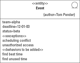
Figure 5-49: User-defined compartment with properties sorted by stereotype.
UML 2.0
UML 2.0 has not changed the specification regarding user-defined compartments.
Modeling Advanced Class Features
So far this chapter has described the most common use of classes. UML provides some additional capabilities. A template class, for example, supports the creation of a variety of classes using parameters to describe the specific type of class. An interface supports the definition of a common way to interact with classes that might not be related.
Modeling a class template
A template is not actually a class in the sense that we have used class throughout this chapter. Instead, it provides a means of customizing a type of class using parameters, hence the alternative name parameterized class. A template defines a type of class such as an array that may be used to store a specified type of object.
Templates are commonly used in C++. Java plans to add them in JDK 1.5.
In order to actually create a usable class from a template, you must supply values for the parameters. For example, a simple array template might require a data type for the type of object that you want to store, and the maximum number of objects you want to store. Figure 5-50 shows a template class, TemplateArray, with two parameters, type and qty defined in the top right corner within the dashed box. Each parameter follows the now familiar format name : datatype. Actually I threw you a curve. The parameter type is actually a shorthand form. Whenever the name of the parameter appears without a corresponding data type, the name of the parameter is assumed to be the data type.

Figure 5-50: Template notation with parameters.
So if I want to store references to a group of people interested in getting a group discount to a show at my theater, I supply the values Customer and 20. To create a useable class, I bind the parameters to the template. The result is a class defined by the combination of the two parameters. In the example in Figure 5-50 I get an array class called Group that can hold up to 20 Customer objects.
UML 2.0
UML 2.0 has not changed the specification regarding template classes.
Modeling an interface
When I defined an operation earlier in this chapter, I pointed out that UML draws a distinction between the means to invoke a behavior and the implementation of a behavior. The means to invoke a behavior is called the operation or operation signature. An operation signature includes the name, parameters, and return-result. The unique combination of these elements defines an interface. The implementation of a behavior, the method, is not modeled in a Class diagram.
Since the interface and implementation are separate, it is possible to define an interface and map it to any number of implementations. In general terms this one-to-many type of mapping between interface and implementations is called polymorphism. Polymorphism can be a powerful tool for building flexibility into an application's design.
The formal definition of polymorphism differs slightly between languages. For example, in C++ if you don't define your method as virtual, you can have multiple implementations in subclasses, but not have them be called polymorphically. In Java, polymorphism is offered by default. To be precise, polymorphism is the ability to dynamically choose which implementation should be called at runtime according to the type of the invoked object.
An interface is a declaration rather than an actual class. As a declaration, an interface has some constraints that classes do not, namely, the operations defined by an interface cannot have any implementation, and interfaces cannot have attributes. The implementation is provided by the class that realizes or implements the interface.
For example, the classes shirt and perfume don't really have anything in common. In a system supporting a retail store, however, the users want to treat both of these different types of objects as products. That is, they want to buy them, inventory them, price them, and sell them. One solution is to add all of these operations to each class. But as the number of different items increases, so does the likelihood that the operations might be defined differently. The code becomes more and more complex as I try to support many different items with many different product-related operations. What I really want is the ability to define once the set of operations that I want to use on all the items that I view as products.
One solution is to isolate the operation signatures in a class by themselves, without any methods, that is, without specifying how the operations must be implemented. This class that only contains the operation signatures is called an interface. Each class that implements this interface is obligated to override all the interface operations to provide their own methods, their own way to satisfy the operation.
Those of you who have programmed in an OO language are probably thinking that an interface sounds a lot like an abstract class. Abstract classes are explained fully in Chapter 6. But it is important to explain here the distinction between an interface and an abstract class.
An abstract class is a class that cannot be instantiated. What prevents it from being instantiated is one of two things. The class is labeled as abstract to explicitly prevent anyone from instantiating it, or at least one operation in the class has no corresponding method. In the second case, if an object was created using this class, the object would not know how to behave when that operation is invoked.
The second case alludes to the most significant difference between an interface and an abstract class. An interface cannot have any methods. An abstract class can have methods for all operations (when explicitly defined as abstract), or for some but not all operations.
Another distinction between abstract classes and interfaces is the fact that abstract classes can define attributes while interfaces cannot. In short, interfaces only define common services that must be supported by implementing classes. Abstract classes can contain any information that is true for all classes that specialize the abstract classes, including attributes, operations, and methods.
Interface notation
One way to accomplish this is to create a quasi class that contains only the operation signatures, like the interface shown in Figure 5-50. I can then apply this interface to each of the classes. Now every class that implements the interface has the same set of operations. Then the implementing classes, shirt and perfume, have to be updated to override the operations and provide their own methods.
UML 1.4 provides two presentation options for interfaces. The first appears in the top right portion of Figure 5-51. It looks like a class with the stereotype «interface». The Shirt class realizes (implements) the interface. This relationship is modeled with the realization symbol, a dashed line with a hollow triangle at the interface end. The diagram is read as “The Shirt class realizes the Product interface.”
The second option is modeled in the bottom of Figure 5-52. The interface is the circle attached to the realizing/implementing Perfume class by a solid line. The size of the circle varies among tools and documents. The important element is the circle and a solid line. Label the circle with the name of the interface.
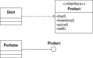
Figure 5-51: Interface notation alternatives.
UML 2.0
Interfaces are defined in the Superstructure::Classes::Interfaces package. Figure 5-52 shows that an interface is a specialization of classifier, so it is a Namespace. It may be generalized and may itself be a specialization of another interface. It can contain other elements, namely attributes and operations. An interface may also nest other interface declarations.
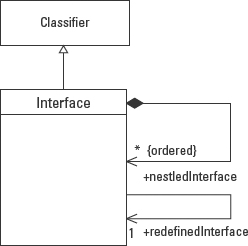
Figure 5-52: Structure::Classes::Interfaces interface definition–Part 1 of 2.
©OMG 2.0
Figure 5-53 shows that an interface may contain any number of attributes and operations. UML 2.0 states that the attributes must be abstract; that is, they cannot be implemented except by the class that realizes the interface. When an interface defines attributes, it is stating a requirement that the instantiating class should maintain that type of information. How it does so is entirely up to the implementing class. At a minimum, the implementing class must define an operation that provides access to the information described by the attribute, even if the attribute itself does not exist. This is very much like the implementation of a derived attribute that the designer chooses not to store.

Figure 5-53: Structure::Classes:: Interfaces interface definition–Part 2 of 2.
©OMG 2.0
Check the syntax of the implementation language to find out whether the language supports the use of attributes in an interface. Java, for example, does not allow instance-level attributes in an interface class.
UML 2.0 enhances the definition of interface class to say that the operations of an interface class can define two types of interfaces: provided and required. A provided interface is a service that the object makes available to other objects. The MarketingPlan, in Figure 5-54, provides the price() operation which can assign a price to a product. Provided interfaces may be modeled as a circle attached to the implementing class by a solid line as in Figure 5-54. (This is sometimes called the lollipop notation.) An interface class can still be modeled as a class with the «interface» stereotype just as was done in UML 1.4.
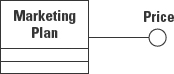
Figure 5-54: Provided interface–the MarketingPlan provides an interface to price products.
When an object requires access to a service, the object is said to have a required interface. In other words, the object needs to find another object that provides the required interface. A required interface can be modeled as a crescent or half circle, as shown in the example in Figure 5-55. The Shirt class requires the Price interface.
Figure 5-55: Required interface–the shirt needs to be priced.
When you put the two together, you get a kind of ball and socket configuration, as illustrated in Figure 5-56. The shirt is a product that needs to be priced and the MarketingPlan provides the ability to price a product.

Figure 5-56: Interconnected provided and required interfaces.
Summary
Chapters 5 and 6 cover the notation for the Class diagram. The focus of Chapter 5 is on the class itself. Chapter 6 explains relationships between classes.
- Class: A class is modeled as a rectangle with three standard compartments for name, attributes, and operations, in that order, and optional user-defined compartments. The name of the class must be unique within a package. When referring to classes with the same name but different owning packages, use the fully qualified name in the format package-name::class-name.
- Attribute: Attributes define the type of information that can be owned and managed by the type of object defined by the class that owns the attributes. Attributes are declared using the syntax:
[visibility] [/] name [: type] [multiplicity] [=default] [{property-string}] - Operation (and method): An operation defines how a behavior can be invoked on an object. The operation is distinct from the method that provides the implementation for the operation. In fact, more than one method may be defined for the same operation in different classes:
[visibility] name ([parameter-list]) ‘:’ [return-result] [{properties}] parameter-list:= name [‘:’ data-type ] [‘[’ multiplicity ‘]’] - Template class: A template class provides a means to define the structure of a class without specifying the type. This technique is useful for container classes such as arrays and Vectors that may contain any type of object. To instantiate a template class you must provide the type.
- Interface: An interface class defines a set of behaviors that an implementing class must support. The operations of an interface class cannot have any methods. The attributes of an interface class must be abstract. That is, the attributes do not have to be declared by the implementing class as long as the implementing class can provide access to the same information through an operation.
- Visibility: Visibility defines the level of access allowed to a model element such as a class, an attribute, or an operation. The allowed visibility values are defined in the enumeration VisibilityKind as private, public, protected, and package.
- Multiplicity: Multiplicity defines the number of values that may be assigned to a model element such as an attribute or a parameter. The number may be expressed as a range, and enumeration, a fixed number, or an undefined limit (*). The syntax for declaring multiplicity is:
multiplicity_range ::= [ lower ‘..’ ] upper
lower ::= integer | value_specification
upper ::= integer | ‘*’ | value_specification
- Multiplicity ordering and uniqueness: Along with the multiplicity values, multiplicity can designate the ordering and the uniqueness of the values in the set bounded by the multiplicity values. The syntax for ordering and uniqueness is as follows:
[ ‘{’ <order_designator> [, <uniqueness_designator>]‘}’ ]
<order_designator> ::= ordered | unordered
<uniqueness_designator> ::= unique | nonunique
![]()