
CHAPTER 17
Representing an Architecture in UML 2.0
![]()
In This Chapter
- Defining the Deployment diagram in UML 2.0
- Defining and modeling nodes and associations
- Defining and modeling components and realizations
- Defining and modeling artifacts and manifestations
- Defining and modeling deployments, deployment targets, deployment specifications, and deployed artifacts
![]()
In UML 2.0, there is a significant change in the vocabulary for modeling runtime environments. UML 1.4 says that components may be used to specify both the requirements for a physical software element and the physical implementation of that element.
UML 2.0 instead opts for a parallel structure, using components and artifacts as represented in Figure 17-1. In this structure, the component is used solely to define the requirements for each physical software element, while an artifact defines the implementation properties for the component.
Each side of the parallel structure for components and artifacts follows the same pattern. A component is defined using a set of one or more classifiers. The same classifier may be used to build any number of components. The specialized dependency Realization maps the refinement of the logical specifications modeled by classifiers that are used to build the component's specification for a physical piece of software.
An artifact is defined using a set of one or more model elements (that is, any PackageableElement). As with classifiers and components, the same model element may be used to construct any number of artifacts. Manifestation, a specialized version of the metaclass Abstraction, maps the evolution of a model element into an artifact.
Figure 17-2 provides an example showing the relationship between these elements on a component diagram.
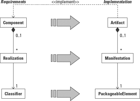
Figure 17-1: UML 2.0 metamodel defines a parallel structure for components and artifacts.

Figure 17-2: An example of the relationship between components and artifacts on a component diagram.
Consequently, in UML 2.0, components only appear in the Component diagram, and artifacts appear on the Deployment diagram. (Technically, artifacts also appear on the Component diagram in order to show the relationship between components and artifacts.) This is very similar to the relationship between objects and classes. Classes form the specification. Objects describe the implementation, or instantiation, of the specification. Likewise, components define the requirements, and artifacts define the implementation.
Table 17-1 summarizes the differences between the two UML releases.
Table 17-1 Deployment Diagram in UML 1.4 and UML 2.0
| UML 1.4 | UML 2.0 |
| Components may be used to define both the requirements for a physical software element, and physical software instances. | Components define only the requirements for physical software elements. |
| Components appear both on the Component diagram and nested in nodes on a Deployment diagram. | Components appear only on the Component diagram. |
| Components are built from a set of one or more realizations. Each realization relationship identifies a classifier that provides the detailed requirements for a component. | |
| Artifacts appear only on Component diagrams to explain the implementation of a component. | Artifacts are nested in nodes on a Deployment diagram as the implementation of a component. |
| Artifacts describe the implementation of a component. | Artifacts describe the implementation of a component. |
| Artifacts are built from a set of one or more manifestations used to implement the requirements for a component. | |
| Realizations describe the classifiers that contain the logical specifications that make up the component requirements. | Manifestations map the relationship between model elements (PackageableElement) and the artifacts that they implement. |
In order to explain how a component is implemented, the model must include a description of the relationship between the components and where they are installed. This relationship is illustrated by combining the Component and Deployment diagrams.
The Component diagram models the software, or procedural elements. The Deployment diagram models the hardware, or processing environment. The artifacts used to implement the component specifications are allocated to processing units called nodes. The nodes are connected to one another to allow communication between the artifacts that reside on them. For example, an HTML Web page, an artifact, might reside on a web server, a node on the Deployment diagram. When a client machine, a second node on the Deployment diagram, wants access to the Web page, it accesses the Web server and loads the page from the server to the client machine across the Internet, the connection between the two nodes.
The combined Component and Deployment diagrams provides a single picture of how artifacts are allocated to nodes, as well as the logical dependencies between the artifacts and the connections between the nodes that support the dependencies. Different combined views can be created to illustrate the installation setup and runtime interactions like loading of software and runtime communication between software artifacts.
The first half of this chapter explains the Deployment diagram. The second half adds artifacts to the Deployment diagram.
Modeling Nodes and Communication Paths
UML 2.0 significantly expands and clarifies the definition of a node. Figure 17-3 is the UML 2.0 metamodel illustrating the changes:
- Node is now a subclass of Class, not Classifier.
- A node may contain other nodes.
- Node is subclassed into devices and execution environments.

Figure 17-3: Node metamodel.
©OMG 2.0
The fact that a node is now a subclass of Class, not Classifier, brings a number of features to a node. Figure 17-4 consolidates the inheritance tree for a node to show the metaclasses from which it gathers all its features. The following description of the node features makes reference to the classes found in this inheritance tree.

Figure 17-4: Node inheritance tree.
From this long and illustrious family tree, the node inherits an extensive list of new features not dealt with (at least not explicitly) in UML 1.4. This makes sense when you recognize that in the early life of the UML the greatest attention was given to the diagrams used to model business applications, that is, Class, Use Case, and Sequence/Collaboration diagrams. Since the release of UML 1.4, the UML 2.0 submitters have had more time to consider the features and usage of the Component and Deployment diagrams.
From Kernel :: Class, node inherits the ability to
- Contain attributes and operations. Attributes may be used to describe the features of a node, such as processor speed, memory capacity, and type of memory. Operations, though rarely used, can describe the services provided by the node via the software contained within it.
- Be specialized. A node, like any other entity, may be described in terms of its features. Servers, for example, come in a variety of configurations and are designed for a variety of purposes. The features of servers may be organized using generalization and specialization to define an inheritance hierarchy of server types thus simplifying the work of defining new server designs.
From InternalStructures :: StructuredClassifier node inherits the ability to
- Be connected to other nodes through associations. Using associations, nodes can be configured into networks.
From BasicBehaviors :: BehavioredClassifier node inherits the ability to
- Own and trigger behaviors. These behaviors are accessed by events received by the node, placed into a queue, and processed if and when a trigger matches the event. Triggers are part of the behavioral specification of the node.
- Own a specification for its own behavior. This description of the operation of the node is in addition to the behaviors housed in the contained components.
From Ports :: Encapsulated Classifier node inherits the ability to
- Own ports. Ports are new to UML 2.0. Ports provide the capability to encapsulate the interfaces to a node. Ports receive requests for the node and delegate those requests to internal parts, software components within the node that supports the requested interface. Ports may also receive requests from within the node and forward them to external interfaces.
 Ports are covered fully in Chapter 5 and Chapter 15.
From Communications :: Class node inherits the ability to
- Be designated active or inactive. When modeling runtime instances of a node, it is possible to designate which nodes are currently active in a scenario and which nodes remain dormant. This view potentially provides insight regarding load balancing.
- Define how it receives signals. In addition to receiving events, a node may receive signals, asynchronous notifications from other nodes. The receipt of a signal does not obligate the node to respond. That decision belongs to the behavior specification for the node. See BasicBehaviors :: BehavioredClassifier earlier.
From StructuredClassifiers :: Class as node inherits the ability to
- Own an internal structure. That is, a node may contain parts.
- Own ports. This extended definition of Class simply combines the features of Ports :: EncapsulatedClassifier and Communications :: Class.
Because a node is a type of class, it may also be stereotyped. Stereotypes can help categorize the expected structure and behavior of a node. Some typical examples of node stereotypes are
- «application server». A “backend» computer that executes applications remotely.
- «client workstation». A computer that executes the user interface portion of applications.
- «mobile device». A computing device that does not need to be connected to other computers, and is designed to be portable.
- «embedded device». A computer that is part of a physical environment, like a piece of automated equipment.
Finally, a node, as defined within the Nodes package, may
- Contain other nodes, but only other nodes. That is, the capability to contain other elements is inherited from Classifiers :: Class, but is then limited to elements typed as nodes. In UML 1.4, a node could contain components. In UML 2.0 a node may only contain nodes, but may be associated with deployed artifacts. This relationship is explored further in the “Deploying Artifacts on Nodes” section later in this chapter.
- Be subclassed into devices and execution environments.
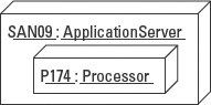
A device is a physical computational resource—a piece of hardware such as a desktop computer, a processor, or a server, for example, or a human work unit such as a department or team. A device is commonly composed of other devices. Composition may be modeled by placing the contained device within the node icon representing the containing device. For example, in Figure 17-5, the application server contains a processor.
An execution environment is a type of node that defines a set of services that support software. For example, an execution environment within the processor on a server in Figure 17-5 might provide the operating system-level services needed to support a database application installed in that environment. Some typical stereotypes for execution environment include «OS», «workflow engine», «database system», and «J2EE container». Figure 17-6 extends Figure 17-5 to add an instance of the J2EEServer execution node, and an instance of the PerformanceEJB component, running in the P174:Processor execution environment.
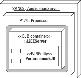
Figure 17-6: An execution environment node that contains a component and runs within a device node. (The gray shading simply highlights the contained execution environment and component.)
Modeling node instantiation
Nodes, like classes, may be described at the specification level (corresponding to a class) or at the instantiation level (corresponding to an object). A node specification uses the same naming convention as a class, a noun that describes the type of node, such as ApplicationServer or DatabaseServer. A node instance follows the naming convention for objects, that is, instance name : node name. Figure 17-7 represents nodes on the left and node instances on the right.

Figure 17-7: Modeling nodes (left) versus node instances (right).
Modeling node communication paths
As Figure 17-8 illustrates, CommunicationPath is a subclass of Association. It specifies the relationship between nodes by defining the number of nodes that may be connected (multiplicity), and the nature of the connection, via the name of the path or a stereotype. This addition in UML 2.0 is simply a refinement of the UML 1.4 use of associations to connect nodes.
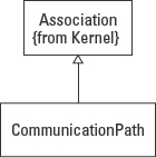
Figure 17-8: CommunicationPath is a subclass/specialization of association.
CommunicationPaths support the modeling of a network of nodes to represent the topology of a physical network. For example, Figure 17-9 represents a simple network with client workstations and printers, an application server, a print server, and two database servers (two instances of the same type). The multiplicities of the CommunicationPaths tell us that any number of client workstations may be connected to the application server (in practice there would be an upper limit). There is one print server attached to the application server. There are between one and five printers attached to the print server. The two database servers support the application server, one as the primary and one as a backup.

Figure 17-9: Network topology using nodes in a Deployment diagram.
UML suggests the use of the three-dimensional node icon, but there is nothing in the standard that requires its use. You are free to associate any icon with a node that you want. The only limitation is in what the tool you use will support. For example, Figure 17-10 draws the same model as Figure 17-9 but with some more familiar icons.

Figure 17-10: Alternative node icons.
Modeling node generalization
Because a node is a type of class, nodes may possess attributes, operations, and associations. In addition, as a subclass of Class, a node may be generalized. That is, properties of nodes that share the same purpose may be organized into sets of shared and unique properties, using superclasses and subclasses, respectively, in an inheritance hierarchy.
For example, Figure 17-11 models a generalization hierarchy of application servers in which application servers may be configured to three standardized specifications depending on the types of applications they support.
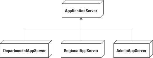
Figure 17-11: Generalizing nodes.
Defining Artifacts
In the transition from design to implementation, every logical construct of the design must be mapped to an implementation element called an artifact. Each artifact represents an actual piece of software (versus a logical specification for software such as a class) that may be addressed in a storage device or within processor memory. Each artifact is a manifestation of one or more model elements. For example, the ContractUserInterface class in a design model may become an HTML page defined to display contract-related content.
 Artifacts may also be found in manual systems as paperwork. But since this book is focused primarily on software system development I chose to keep all the examples related to software systems.
Figure 17-12 is the metamodel of the Artifacts package. Referring to the model, an artifact is a type of classifier. As such, it may own properties (attributes) and operations. This makes sense because an artifact is the physical manifestation of the logical requirements defined by a class. In addition, an artifact may be named to uniquely identify it within a file structure.

Figure 17-12: Artifact package metamodel.
©OMG 2.0
An artifact may be composed of other artifacts (see nestedArtifact in Figure 17-12). For example, the user interface artifact for a contract could be implemented using a Java Servlet that includes the specification for an HTML page, compressed into a jar file. (Later, you will see how the rules for deploying an artifact may be embedded within the artifact as well.)
Now, in order to describe how an artifact is created, the model draws a relationship called a manifestation, between the artifact and the elements used in its construction. Figure 17-13 adds the manifestation portion of the Artifacts package to model the rules for this relationship. A manifestation is a type of dependency; specifically it is a type of abstraction dependency. It is drawn as a dashed arrow between the artifact and each element utilized by the artifact (see Figure 17-14).

Figure 17-13: Manifestations used to create an artifact.
©OMG 2.0
The utilized elements may be any type of packageable element, that is, pretty much anything in the model that can be named. In Chapter 15, a component was defined as the specification for a physical artifact. A component is defined in terms of classifiers that together describe all the features of the component. Because an artifact implements the component requirements, the artifact might use the same classifiers or corresponding packageable elements that represent physical implementation of the classifiers. For example, Figure 17-14 represents the relationship between the ContractHTML file and the ContractUI class, that is, the ContractHTML file manifests the specification of the ContractUI class in a specific technology.

Figure 17-14: The manifestation dependency between an artifact and a model element.
Notice the notation for the artifact: a rectangle with a file icon in the top right corner. An artifact may also simply use a rectangle with the stereotype «artifact», as shown in Figure 17-15.
![]()
Figure 17-15: Alternative notation for artifacts.
The example in Figure 17-14 highlights an important benefit of modeling the relationship between artifacts and the elements used to manifest, or produce, the artifact. The basic principles of object-oriented design constantly strive to separate programming concerns—operation and method, interface and implementation (in terms of behavior and data), and control—from structure using stereotyped classes. An artifact may be manifested in any number of technological alternatives. Using the previous example, the same artifact might be generated using a Java Server Page instead of a Servlet.
Stereotypes can simplify the work of defining artifacts. At a high level of abstraction, artifacts might be distinguished as «source» versus «executable» artifacts. Furthermore, given that developers typically spend considerable time in one particular set of technologies, it is also useful to stereotype artifacts to represent the standard set of elements used in a technology platform. For example, Java developers might utilize JSPs, EJBs, Servlets, and HTML. To facilitate the definition of artifacts, the team may choose to establish a profile that includes these element types as standard artifact stereotypes, that is, «JSP», «EJB», «Servlet», and «HTML».
Deploying Artifacts on Nodes
An artifact must be deployed in order to be used. That is, it must be placed in a location where it may be stored and used. The target of the deployment may be a node, that is, an execution environment or a device, a property, or an instance specification. The relationship between the location and the artifact is defined by the Deployment dependency relationship.
Figure 17-16 is the metamodel for deployments found in the Nodes package. Deployment target is an abstract class used to identify the common features of elements that may be used as the location to deploy an artifact. By defining the deployment target and artifacts separately, the model supports a mix-and-match approach to the assembly of software and hardware elements to craft any number of implementation solutions for a design.
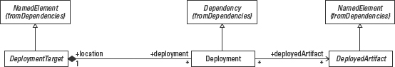
Figure 17-16: Deployment metamodel.
©OMG 2.0
DeploymentTarget and DeploymentArtifact are abstract metaclasses. Figure 17-17 shows how deployment targets may be nodes, properties, or instance specifications, and deployed artifacts may either be artifacts, as previously defined, or instance specifications.
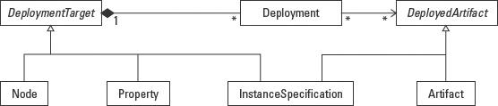
Figure 17-17: Types of deployment targets and deployed artifacts.
©OMG 2.0
A deployment is modeled as a stereotyped dependency. This dependency may be modeled in any of three ways, as illustrated in Figure 17-18. The ContractUI.jar artifact is deployed on the ClientWorkstation. In the first example the deployment dependency is modeled as a dashed arrow from the node to the artifact with the optional stereotype «deploy». In the second example, the artifact icon is physically located within the node icon. In the third example, the artifacts are listed textually within the node icon.
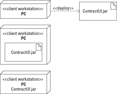
Figure 17-18: Alternative notations for deploying an artifact on a node.
The definition of an artifact is further specialized in a DeploymentSpecification. A deployment specification adds properties that describe the execution parameters for an artifact. The parameters are synchronized with the type of execution environment on which the artifact is deployed. In other words, a deployment specification defines the relationship between a specific execution environment and the execution of a specific artifact.
Figure 17-19 reveals two properties of a deployment specification. The deploymentLocation identifies where the artifact is loaded onto the node in terms of a directory or memory location. For example, the ContractUI.jar might be stored in the application's directory on the client. The executionLocation identifies the execution environment in which the artifact runs. The ContractUI executes in the java virtual machine (JVM) on the client workstation.
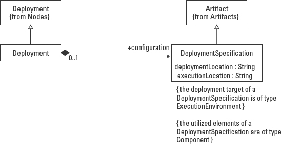
Figure 17-19: Deployment specification metamodel.
©OMG 2.0
The parameters for execution defined by a deployment specification may include concurrency, execution, and transaction-specific options expressed as tagged values:
- concurrencyMode—including thread, process, and none (sequential)
- executionMode—including local, remote, and none
- transactionMode—including transaction, nestedTransaction, and none
Of course, you may also add your own tagged values.
The element that contains the specification values is itself an artifact, such as an XML document or a text file. Modeling a deployment specification implies the need to represent the definition of the specification as well as the instances actually applied to artifacts. UML 2.0 uses approximately the same notation as for classes and objects as shown in Figure 17-20.
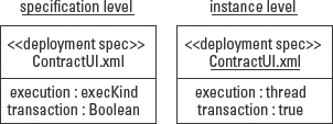
Figure 17-20: Deployment specification notation.
Applying the deployment specification to an artifact requires a way to model the relationship. UML 2.0 offers two alternatives, shown in Figure 17-21. The first example models the deployment specification as a separate model element with a dependency arrow from the specification to the artifact to which it applies. The second example models the deployment specification as a set of properties within the artifact icon.
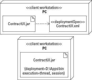
Figure 17-21: Modeling an artifact specification.
Summary
UML 2.0 supports a combined view of the Component and Deployment diagrams that illustrates how software is implemented in the computing environment. Components are represented by artifacts that implement the requirements specified by the components in a Component diagram. Nodes and connections on a Deployment diagram provide the deployment and execution locations for the artifacts.
- Component: A component defines the requirements for an implementation of the features specified in a Class diagram. A component realizes the features of classes (classifiers).
- Artifact: An artifact defines the implementation of a component in a specific technology. An artifact manifests the features of one or more packageable elements used to describe a physical implementation.
- Node: A node is either a device or an execution environment within a device. (For manual processes a node may be an organizational unit.)
- Communication path: A communication path is the physical connection between nodes.
- Deployment specification: A deployment specification defines how an artifact is allocated to a node, including the concurrency mode, execution mode, and the transaction mode.
Dependencies model the types of relationships between model elements that represent different levels of specification within a model. Dependencies on a combined Component and Deployment diagram are modeled as a dashed arrow with one of the following stereotypes:
- Realization: A component realizes, or describes the requirements for implementing, the features of one or more classifiers.
- Manifest: An artifact manifests, or defines a specific implementation for, the features of one or more physical software elements.
- Implement: An artifact implements, or defines one implementation for the requirements defined by a component.
- Deploy: A node deploys, provides a place to store and/or execute, an artifact.