The concepts described in Chapter 3 correspond to the key notations in class diagrams. Those concepts are the first ones to understand and become familiar with, as they will comprise 90 percent of your effort in building class diagrams.
The class diagram technique, however, has bred dozens of notations for additional concepts. I find that I don’t use these all the time, but they are handy when they are appropriate. I’ll discuss them one at a time and point out some of the issues in using them.
You’ll probably find this chapter somewhat heavy going. The good news is that during your first pass through the book, you can safely skip this chapter and come back to it later.
One of the challenges of a graphical language is that you have to remember what the symbols mean. With too many, users find it very difficult to remember what all the symbols mean. So the UML often tries to reduce the number of symbols and use keywords instead. If you find that you need a modeling construct that isn’t in the UML but is similar to something that is, use the symbol of the existing UML construct but mark it with a keyword to show that you have something different
An example of this is the interface. A UML interface (page 69) is a class that has only public operations, with no method bodies. This corresponds to interfaces in Java, COM (Component Object Module), and CORBA. Because it’s a special kind of class, it is shown using the class icon with the keyword «interface». Keywords are usually shown as text between guillemets. As an alternative to keywords, you can use special icons, but then you run into the issue of everyone having to remember what they mean.
Some keywords, such as {abstract}, show up in curly brackets. It’s never really clear what should technically be in guillemets and what should be in curlies. Fortunately, if you get it wrong, only serious UML weenies will notice—or care.
Some keywords are so common that they often get abbreviated: «interface» often gets abbreviated to «I» and {abstract} to {A}. Such abbreviations are very useful, particularly on whiteboards, but nonstandard, so if you use them, make sure you find a spot to spell out what they mean.
In UML 1, the guillemets were used mainly for stereotypes. In UML 2, stereotypes are defined very tightly, and describing what is and isn’t a stereotype is beyond the scope of this book. However, because of UML 1, many people use the term stereotype to mean the same as keyword, although that is no longer correct.
Stereotypes are used as part of profiles. A profile takes a part of the UML and extends it with a coherent group of stereotypes for a particular purpose, such as business modeling. The full semantics of profiles are beyond this book. Unless you are into serious meta-model design, you’re unlikely to need to create one yourself. You’re more likely to use one created for a specific modeling purpose, but fortunately, use of a profile doesn’t require you to know the gory details of how they are tied into the meta-model.
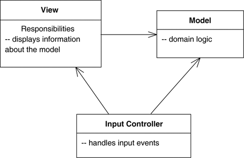
Often, it’s handy to show responsibilities (page 63) on a class in a class diagram. The best way to show them is as comment strings in their own compartment in the class (Figure 5.1). You can name the compartment, if you wish, but I usually don’t, as there’s rarely any potential for confusion.
The UML refers to an operation or an attribute that applies to a class rather than to an instance as static. This is equivalent to static members in C-based languages. Static features are underlined on a class diagram (see Figure 5.2).
One of the most frequent sources of confusion in the UML is aggregation and composition. It’s easy to explain glibly: Aggregation is the part-of relationship. It’s like saying that a car has an engine and wheels as its parts. This sounds good, but the difficult thing is considering what the difference is between aggregation and association.
In the pre-UML days, people were usually rather vague on what was aggregation and what was association. Whether vague or not, they were always inconsistent with everyone else. As a result, many modelers think that aggregation is important, although for different reasons. So the UML included aggregation (Figure 5.3) but with hardly any semantics. As Jim Rumbaugh says, “Think of it as a modeling placebo” [Rumbaugh, UML Reference].
As well as aggregation, the UML has the more defined property of composition. In Figure 5.4, an instance of Point may be part of a polygon or may be the center of a circle, but it cannot be both. The general rule is that, although a class may be a component of many other classes, any instance must be a component of only one owner. The class diagram may show multiple classes of potential owners, but any instance has only a single object as its owner.
You’ll note that I don’t show the reverse multiplicities in Figure 5.4. In most cases, as here, it’s 0..1. Its only other possible value is 1, for cases in which the component class is designed so that it can have only one other class as its owner.
The “no sharing” rule is the key to composition. Another assumption is that if you delete the polygon, it should automatically ensure that any owned Points also are deleted.
Composition is a good way of showing properties that own by value, properties to value objects (page 73), or properties that have a strong and somewhat exclusive ownership of particular other components. Aggregation is strictly meaningless; as a result, I recommend that you ignore it in your own diagrams. If you see it in other people’s diagrams, you’ll need to dig deeper to find out what they mean by it. Different authors and teams use it for very different purposes.
Derived properties can be calculated based on other values. When we think about a date range (Figure 5.5), we can think of three properties: the start date, the end date, and the number of days in the period. These values are linked, so we can think of the length as being derived from the other two values.
Derivation in software perspectives can be interpreted in a couple of different ways. You can use derivation to indicate the difference between a calculated value and a stored value. In this case, we would interpret Figure 5.5 as indicating that the start and end are stored but that the length is computed. Although this is a common use, I’m not so keen, because it reveals too much of the internals of DateRange.
My preferred thinking is that it indicates a constraint between values. In this case, we are saying that the constraint among the three values holds, but it isn’t important which of the three values is computed. In this case, the choice of which attribute to mark as derived is arbitrary and strictly unnecessary, but it’s useful to help remind people of the constraint. This usage also makes sense with conceptual diagrams.
Derivation can also be applied to properties using association notation. In this case, you simply mark the name with a /.
An abstract class is a class that cannot be directly instantiated. Instead, you instantiate an instance of a subclass. Typically, an abstract class has one or more operations that are abstract. An abstract operation has no implementation; it is pure declaration so that clients can bind to the abstract class.
The most common way to indicate an abstract class or operation in the UML is to italicize the name. You can also make properties abstract, indicating an abstract property or accessor methods. Italics are tricky to do on a whiteboards, so you can use the label: {abstract}.
An interface is a class that has no implementation; that is, all its features are abstract. Interfaces correspond directly to interfaces in C# and Java and are a common idiom in other typed languages. You mark an interface with the keyword «interface».
Classes have two kinds of relationships with interfaces: providing and requiring. A class provides an interface if it is substitutable for the interface. In Java and .NET, a class can do that by implementing the interface or implementing a subtype of the interface. In C++, you subclass the class that is the interface.
A class requires an interface if it needs an instance of that interface in order to work. Essentially, this is having a dependency on the interface.
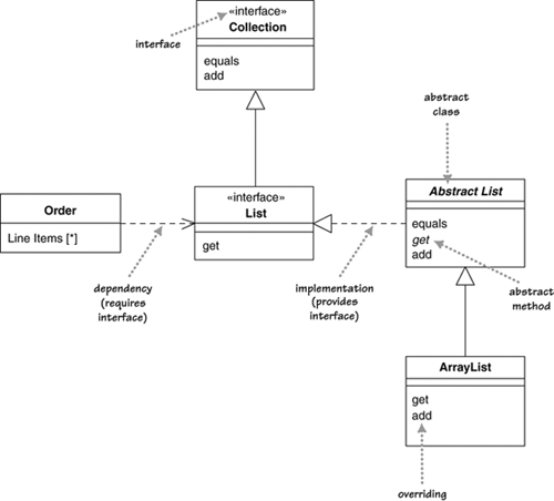
Figure 5.6 shows these relationships in action, based on a few collection classes from Java. I might write an Order class that has a list of line items. Because I’m using a list, the Order class is dependent on the List interface. Let’s assume that it uses the methods equals, add, and get. When the objects connect, the Order will actually use an instance of ArrayList but need not know that in order to use those three methods, as they are all part of the List interface.
The ArrayList itself is a subclass of the AbstractList class. AbstractList provides some, but not all, the implementation of the List behavior. In particular, the get method is abstract. As a result, ArrayList implements get but also overrides some of the other operations on AbstractList. In this case, it overrides add but is happy to inherit the implementation of equals.
Why don’t I simply avoid this and have Order use ArrayList directly? By using the interface, I allow myself the advantage of making it easier to change implementations later on if I need to. Another implementation may provide performance improvements, some database interaction features, or other benefits. By programming to the interface rather than to the implementation, I avoid having to change all the code should I need a different implementation of List. You should always try to program to an interface like this; always use the most general type you can.
I should also point out a pragmatic wrinkle in this. When programmers use a collection like this, they usually initialize the collection with a declaration, like this:
private List lineItems = new ArrayList();
Note that this strictly introduces a dependency from Order to the concrete ArrayList. In theory, this is a problem, but people don’t worry about it in practice. Because the type of lineItems is declared as List, no other part of the Order class is dependent on ArrayList. Should we change the implementation, there’s only this one line of initialization code that we need to worry about. It’s quite common to refer to a concrete class once during creation but to use only the interface afterward.
The full notation of Figure 5.6 is one way to notate interfaces. Figure 5.7 shows a more compact notation. The fact that ArrayList implements List and Collection is shown by having ball icons, often referred to as lollipops, out of it. The fact that Order requires a List interface is shown by the socket icon. The connection is nicely obvious.
The UML has used the lollipop notation for a while, but the socket notation is new to UML 2. (I think it’s my favorite notational addition.) You’ll probably see older diagrams use the style of Figure 5.8, where a dependency stands in for the socket notation.
Any class is a mix of an interface and an implementation. Therefore, we may often see an object used through the interface of one of its superclasses. Strictly, it wouldn’t be legal to use the lollipop notation for a superclass, as the superclass is a class, not a pure interface. But I bend these rules for clarity.
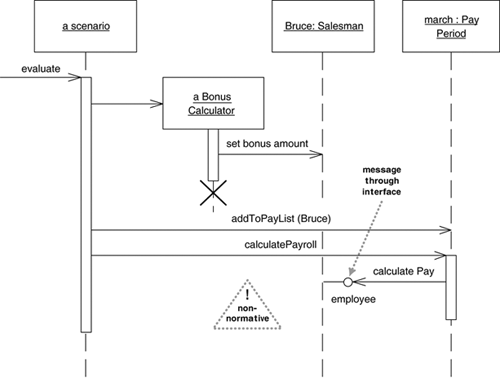
As well as on class diagrams, people have found lollipops useful elsewhere. One of the perennial problems with interaction diagrams is that they don’t provide a very good visualization for polymorphic behavior. Although it’s not normative usage, you can indicate this along the lines of Figure 5.9. Here, we can see that, although we have an instance of Salesman, which is used as such by the Bonus Calculator, the Pay Period object uses the Salesman only through its Employee interface. (You can do the same trick with communication diagrams.)
On page 37, I described the {readOnly} keyword. You use this keyword to mark a property that can only be read by clients and that cannot be updated. Similar yet different is the {frozen} keyword from UML 1. A property is frozen if it cannot change during the lifetime of an object; such properties are often called immutable. Although it was dropped from UML 2, {frozen} is a very useful concept, so I would continue to use it. As well as marking individual properties as frozen, you can apply the keyword to a class to indicate that all properties of all instances are frozen. (I have heard that frozen may well be reinstated shortly.)
One of the common things said about objects is that they have identity. This is true, but it is not quite as simple as that. In practice, you find that identity is important for reference objects but not so important for value objects.
Reference objects are such things as Customer. Here, identity is very important because you usually want only one software object to designate a customer in the real world. Any object that references a Customer object will do so through a reference, or pointer; all objects that reference this Customer will reference the same software object. That way, changes to a Customer are available to all users of the Customer.
If you have two references to a Customer and wish to see whether they are the same, you usually compare their identities. Copies may be disallowed; if they are allowed, they tend to be made rarely, perhaps for archive purposes or for replication across a network. If copies are made, you need to sort out how to synchronize changes.
Value objects are such things as Date. You often have multiple value objects representing the same object in the real world. For example, it is normal to have hundreds of objects that designate 1-Jan-04. These are all interchangeable copies. New dates are created and destroyed frequently.
If you have two dates and wish to see whether they are the same, you don’t look at their identities but rather at the values they represent. This usually means that you have to write an equality test operator, which for dates would make a test on year, month, and day—or whatever the internal representation is. Each object that references 1-Jan-04 usually has its own dedicated object, but you can also share dates.
Value objects should be immutable; in other words, you should not be able to take a date object of 1-Jan-04 and change the same date object to be 2-Jan-04. Instead, you should create a new 2-Jan-04 object and use that instead. The reason is that if the date were shared, you would update another object’s date in an unpredictable way, a problem referred to as aliasing.
In days gone by, the difference between reference objects and value objects was clearer. Value objects were the built-in values of the type system. Now you can extend the type system with your own classes, so this issue requires more thought.
The UML uses the concept of data type, which is shown as a keyword on the class symbol. Strictly, data type isn’t the same as value object, as data types can’t have identity. Value objects may have an identity, but don’t use it for equality. Primitives in Java would be data types, but dates would not, although they would be value objects.
If it’s important to highlight them, I use composition when associating with a value object. You can also use a keyword on a value type; common conventional ones I see are «value» or «struct».
A qualified association is the UML equivalent of a programming concept variously known as associative arrays, maps, hashes, and dictionaries. Figure 5.10 shows a way that uses a qualifier to represent the association between the Order and Order Line classes. The qualifier says that in connection with an Order, there may be one Order Line for each instance of Product.
From a software perspective, this qualified association would imply an interface along the lines of
class Order ...
  public OrderLine getLineItem(Product aProduct);
  public void addLineItem(Number amount, Product forProduct);
Thus, all access to a given Order Line requires a Product as an argument, suggesting an implementation using a key and value data structure.
It’s common for people to get confused about the multiplicities of a qualified association. In Figure 5.10, an Order may have many Line Items, but the multiplicity of the qualified association is the multiplicity in the context of the qualifier. So the diagram says that an Order has 0..1 Line Items per Product. A multiplicity of 1 would indicate that Order would have to have a Line Item for every instance of Product. A * would indicate that you would have multiple Line Items per Product but that access to the Line Items is indexed by Product.
In conceptual modeling, I use the qualifier construct only to show constraints along the lines of “single Order Line per Product on Order.”
I often hear people talk about subtyping as the is a relationship. I urge you to beware of that way of thinking. The problem is that the phrase is a can mean different things.
Consider the following phrases.
Shep is a Border Collie.
A Border Collie is a Dog.
Dogs are Animals.
A Border Collie is a Breed.
Dog is a Species.
Now try combining the phrases. If I combine phrases 1 and 2, I get “Shep is a Dog”; 2 and 3 taken together yield “Border Collies are Animals.” And 1 plus 2 plus 3 gives me “Shep is an Animal.” So far, so good. Now try 1 and 4: “Shep is a Breed.” The combination of 2 and 5 is “A Border Collie is a Species.” These are not so good.
Why can I combine some of these phrases and not others? The reason is that some are classification—the object Shep is an instance of the type Border Collie—and some are generalization—the type Border Collie is a subtype of the type Dog. Generalization is transitive; classification is not. I can combine a classification followed by a generalization but not vice versa.
I make this point to get you to be wary of is a. Using it can lead to inappropriate use of subclassing and confused responsibilities. Better tests for subtyping in this case would be the phrases “Dogs are kinds of Animals” and “Every instance of a Border Collie is an instance of a Dog.”
The UML uses the generalization symbol to show generalization. If you need to show classification, use a dependency with the «instantiate» keyword.
Classification refers to the relationship between an object and its type. Mainstream programming languages assume that an object belongs to a single class. But there are more options to classification than that.
In single classification, an object belongs to a single type, which may inherit from supertypes. In multiple classification, an object may be described by several types that are not necessarily connected by inheritance.
Multiple classification is different from multiple inheritance. Multiple inheritance says that a type may have many supertypes but that a single type must be defined for each object. Multiple classification allows multiple types for an object without defining a specific type for the purpose.
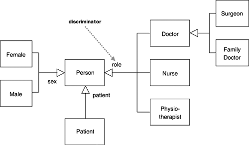
For example, consider a person subtyped as either man or woman, doctor or nurse, patient or not (see Figure 5.11). Multiple classification allows an object to have any of these types assigned to it in any allowable combination, without the need for types to be defined for all the legal combinations.
If you use multiple classification, you need to be sure that you make it clear which combinations are legal. UML 2 does this by placing each generalization relationship into a generalization set. On the class diagram, you label the generalization arrowhead with the name of the generalization set, which in UML 1 was called the discriminator. Single classification corresponds to a single generalization set with no name.
Generalization sets are by default disjoint: Any instance of the supertype may be an instance of only one of the subtypes within that set. If you roll up generalizations into a single arrow, they must all be part of the same generalization set, as shown in Figure 5.11. Alternatively, you can have several arrows with the same text label.
To illustrate, note the following legal combinations of subtypes in the diagram: (Female, Patient, Nurse); (Male, Physiotherapist); (Female, Patient); and (Female, Doctor, Surgeon). The combination (Patient, Doctor, Nurse) is illegal because it contains two types from the role generalization set.
Another question is whether an object may change its class. For example, when a bank account is overdrawn, it substantially changes its behavior. Specifically, several operations, including “withdraw” and “close,” get overridden.
Dynamic classification allows objects to change class within the subtyping structure; static classification does not. With static classification, a separation is made between types and states; dynamic classification combines these notions.
Should you use multiple, dynamic classification? I believe that it is useful for conceptual modeling. For software perspectives, however, the distance between it and the implementations is too much of a leap. In the vast majority of UML diagrams, you’ll see only single static classification, so that should be your default.
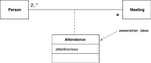
Association classes allow you to add attributes, operations, and other features to associations, as shown in Figure 5.12. We can see from the diagram that a person may attend many meetings. We need to keep information about how awake that person was; we can do this by adding the attribute attentiveness to the association.
Figure 5.13 shows another way to represent this information: Make Attendance a full class in its own right. Note how the multiplicities have moved.
What benefit do you gain with the association class to offset the extra notation you have to remember? The association class adds an extra constraint, in that there can be only one instance of the association class between any two participating objects. I feel the need for another example.
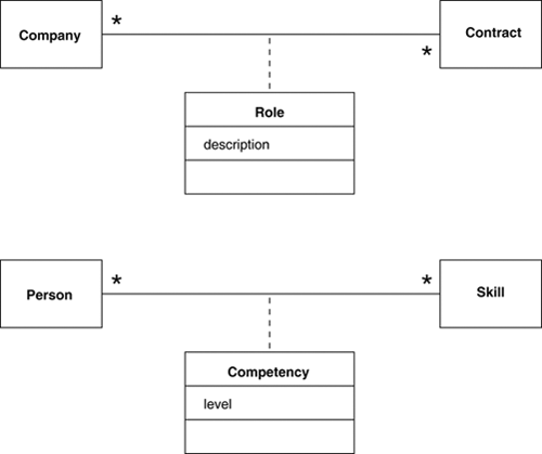
Take a look at the two diagrams in Figure 5.14. These diagrams have much the same form. However, we can imagine one Company playing different roles in the same Contract, but it’s harder to imagine a Person having multiple competencies in the same skill; indeed, you would probably consider that an error.
In the UML, only the latter case is legal. You can have only one competency for each combination of Person and Skill. The top diagram in Figure 5.14 would not allow a Company to have more than one Role on a single contract. If you need to allow this, you need to make Role a full class, in the style of Figure 5.13.
Implementing association classes isn’t terribly obvious. My advice is to implement an association class as if it where a full class but to provide methods that get information to the classes linked by the association class. So for Figure 5.12, I would see the following methods on Person:
class Person
  List getAttendances()
  List getMeetings()
This way, a client of Person can get hold of the people at the meeting; if they want details, they can get the Attendances themselves. If you do this, remember to enforce the constraint that there can be only one Attendance object for any pair of Person and Meeting. You should place a check in whichever method creates the Attendance.
You often find this kind of construct with historical information, such as in Figure 5.15. However, I find that creating extra classes or association classes can make the model tricky to understand, as well as tilt the implementation in a particular direction that’s often unsuitable.
If I have this kind of temporal information, I use a «temporal» keyword on the association (see Figure 5.16). The model indicates that a Person may work for only a single Company at one time. Over time, however, a Person may work for several Companies. This suggests an interface along the lines of:
class Person ...
  Company getEmployer();//get current employer
  Company getEmployer(Date);//get employer at a given date
  void changeEmployer(Company newEmployer,Date changeDate);
  void leaveEmployer (Date changeDate);
The «temporal» keyword is not part of the UML, but I mention it here for two reasons. First, it is a notion I have found useful on several occasions in my modeling career. Second, it shows how you can use keywords to extend the UML. You can read a lot more about this at http://martinfowler.com/ap2/timeNarrative.html.
Several languages, most noticeably C++, have the notion of a parameterized class, or template. (Templates are on the list to be included in Java and C# in the near future.)
This concept is most obviously useful for working with collections in a strongly typed language. This way, you can define behavior for sets in general by defining a template class Set.
class Set <T> {
  void insert (T newElement);
  void remove (T anElement);
When you have done this, you can use the general definition to make Set classes for more specific elements:
Set <Employee> employeeSet;
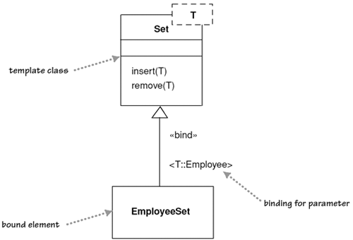
You declare a template class in the UML by using the notation shown in Figure 5.17. The T in the diagram is a placeholder for the type parameter. (You may have more than one.)
A use of a parameterized class, such as Set<Employee>, is called a derivation. You can show a derivation in two ways. The first way mirrors the C++ syntax (see Figure 5.18). You describe the derivation expression within angle brackets in the form <parameter-name::parameter-value>. If there’s only one parameter, conventional use often omits the parameter name. The alternative notation (see Figure 5.19) reinforces the link to the template and allows you to rename the bound element.
The «bind» keyword is a stereotype on the refinement relationship. This relationship indicates that EmployeeSet will conform to the interface of Set. You can think of the EmployeeSet as a subtype of Set. This fits the other way of implementing type-specific collections, which is to declare all appropriate subtypes.
Using a derivation is not the same as subtyping, however. You are not allowed to add features to the bound element, which is completely specified by its template; you are adding only restricting type information. If you want to add features, you must create a subtype.
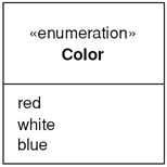
Enumerations (Figure 5.20) are used to show a fixed set of values that don’t have any properties other than their symbolic value. They are shown as the class with the «enumeration» keyword.
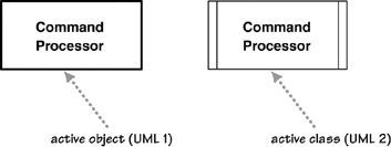
An active class has instances, each of which executes and controls its own thread of control. Method invocations may execute in a client’s thread or in the active object’s thread. A good example of this is a command processor that accepts command objects from the outside and then executes the commands within its own thread of control.
The notation for active classes has changed from UML 1 to UML 2, as shown in Figure 5.21. In UML 2, an active class has extra vertical lines on the side; in UML 1, it had a thick border and was called an active object.
Visibility is a subject that is simple in principle but has complex subtleties. The simple idea is that any class has public and private elements. Public elements can be used by any other class; private elements can be used only by the owning class. However, each language makes its own rules. Although many languages use such terms as public, private, and protected, they mean different things in different languages. These differences are small, but they lead to confusion, especially for those of us who use more than one language.
The UML tries to address this without getting into a horrible tangle. Essentially, within the UML, you can tag any attribute or operation with a visibility indicator. You can use any marker you like, and its meaning is language dependent. However, the UML provides four abbreviations for visibility: + (public), – (private), ~ (package), and # (protected). These four levels are used within the UML meta-model and are defined within it, but their definitions vary subtly from those in other languages.
When you are using visibility, use the rules of the language in which you are working. When you are looking at a UML model from elsewhere, be wary of the meanings of the visibility markers, and be aware of how those meanings can change from language to language.
Most of the time, I don’t draw visibility markers in diagrams; I use them only if I need to highlight the differences in visibility of certain features. Even then, I can mostly get away with + and –, which at least are easy to remember.
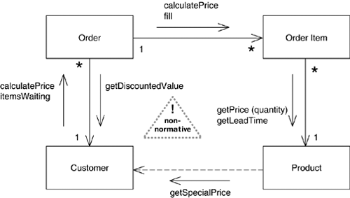
Standard UML does not show any information about message calls on class diagrams. However, I’ve sometimes seen conventional diagrams like Figure 5.22.
These add arrows to the sides of associations. The arrows are labeled with the messages that one object sends to another. Because you don’t need an association to a class to send a message to it, you may also need to add a dependency arrow to show messages between classes that aren’t associated.
This message information spans multiple use cases, so they aren’t numbered to show sequences, unlike communication diagrams.
