
In this final chapter, we’ll create a small minigame without writing a single line of code. The game will be a simple ball rolling–style game, where the objective will be to roll a ball down a garden path, collecting strewn objects until the time runs out. It won’t be a full-blown ball-rolling puzzle game, but you could easily achieve one by further coding simple mechanics if you want to. You could have the ball grow in size as the player picks up objects, or you could have the player start out by picking up medium-sized objects until the Ball has grown to a specific size, at which point the player will graduate to picking up larger objects and then complete the level.
In this chapter, you’ll learn to develop the core mechanic of having a ball roll around and pick up objects. You’ll also set up a timer that counts down the seconds you have left to complete the level, and when it reaches zero, it won’t allow you to roll the ball any further. We’ll use the Slide movement mode of locomotion to move through the scene. This will be implemented using our Left Controller’s Thumbstick, as we set up in Chapter 10, “Seamless Locomotion.” Our Right Controller’s Thumbstick will be used to control the Ball, allowing it to move forward, backward, left, and right. The Countdown Timer will be set up as a spatial UI Tooltip that will display the seconds you have remaining to collect all objects win the level. Along the way, you’ll learn how to set up a Moment Processor and an event that will be called once a specific time interval has elapsed.
We’ll also use the VRTK’s Input Combined Actions Axes to Vector 3 Action prefab to roll the Ball around by adding force to the Ball’s rigid body. Attempting to achieve this realistic ball movement without using the VRTK-provided Input Combined Actions Axes to Vector 3 Action prefab would require you to write math-intensive code involving vectors and trigonometry. But thanks to this VRTK prefab , you don’t need to code this pretty complicated stuff yourself.
Importing the Base Unity Package
We’ll use the same VR Playground project here, as it already comprises all the required Tilia Packages and the entire VRTK SETUP created with this book. In this case, we’ll utilize only those prefabs required to build our minigame.

The garden path populated with 37 game objects

The Fruit Pear game object’s Basic Animator component with its Sphere Collider’s Is Trigger property checked off
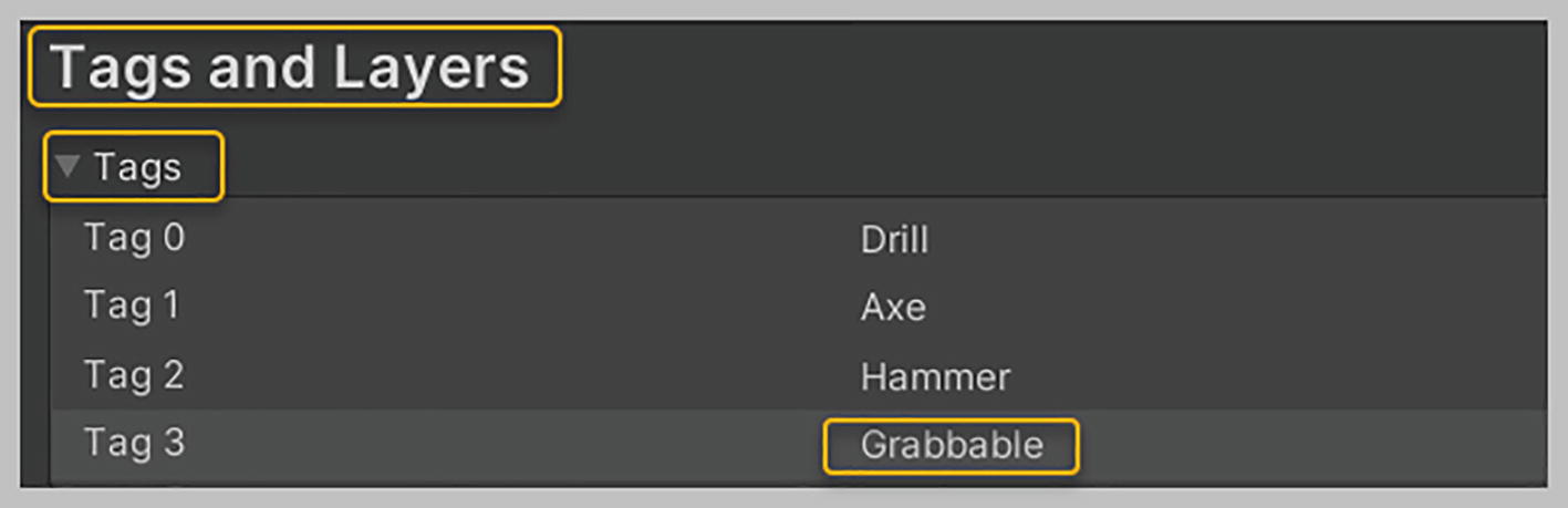
Creating the Grabbable tag in Tags and Layers
We next need to set up the VRTK-provided Collision Tracker component on each of the 37 obstacle game objects in your garden path. Let’s first set up this component on the Fruit Apple obstacle. To do so, expand the Environment game object in the hierarchy, then select the Fruit Apple game object, and in the Inspector, click the Add Component button and add a new Collision Tracker component. Set its Emitted Types property to Trigger. Set its States to Process property to Enter, which indicates that you’re looking for an On Trigger Enter Collision to occur against your Fruit Apple Obstacle. Once this On Trigger Enter state has been reached, the Collision Started Event listed in the “Collision Event” section will be triggered. Here you need to set the Fruit Apple obstacle game object’s Tag value to Grabbable. Let’s set this up.
Click the plus symbol located in the bottom right corner of the Collision Started Event to add an event listener. Then, drag and drop the Fruit Apple obstacle game object into this event listener box. For this function, select Collision Tracker, String, Tag. In the text box below, type in “Grabbable.” Ensure that you spell it exactly as shown in Figure 22-3.

Setting up the Fruit Apple obstacle game object with a Collision Tracker component

Setting up the Collision Tracker for 22 of the 36 obstacle game objects

Setting up the Collision Tracker on the remaining 14 obstacle game objects

Exploring the setup of the Ball game object
Setting Up the VRTK Prefabs
In this section, we’ll create prefabs of certain game objects in the Demo scene that are required by the Garden scene to set up its VR functionality. Let’s start by launching the Demo scene and creating a new folder in the “Assets” folder and naming it “Prefabs.” Then, with the Demo scene open, expand the VRTK SETUP game object, and drag and drop its child game object, VRTK CAMERA RIGS SETUP, from within it to the newly created “Prefabs” folder. You now have a VRTK CAMERA RIGS SETUP prefab that can be used in any other scene of your project.

The VRTK PSEUDOBODY prefab with several broken property links
Within the Demo scene, select and expand the Button Input Actions game object in the hierarchy. Drag and drop the Thumbstick Horizontal Axis Input game object into the “Prefabs” folder. When asked whether you want to create an original prefab or a variant of this prefab, select Original Prefab. Then, drag and drop the Thumbstick Vertical Axis Input game object into the “Prefabs” folder. When asked whether you want to create a new original prefab or a variant of this prefab, select Original Prefab.
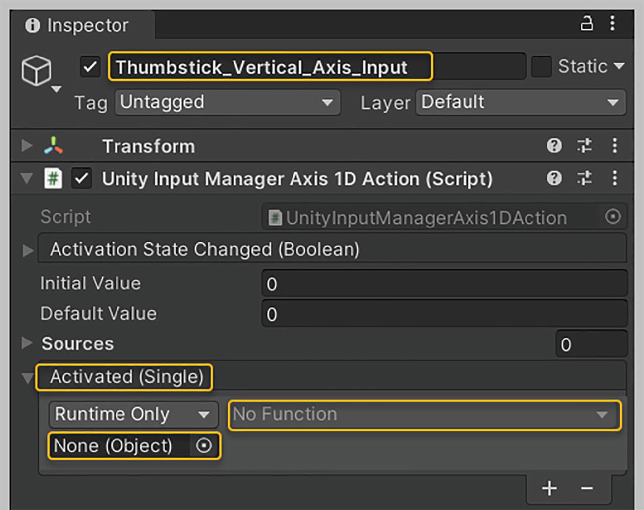
The Thumbstick Vertical Axis Input prefab with its Activated event broken
Finally, as we’ll be using just one of the Slide movements for locomotion, we’ll set up this locomotion method from scratch directly in the Garden scene. Let’s start setting up the various VRTK prefabs in the Garden scene.
Launch the Garden scene. With the Garden game object selected in the hierarchy, navigate to the Assets ➤ “Prefabs” folder, and drag and drop in the VRTK CAMERA RIGS SETUP prefab. With the VRTK CAMERA RIGS SETUP game object selected, set its Transform Position property values as follows: X = 5; Y = 0; and Z = -38. This ensures that you start out positioned behind the Ball.
Now, expand the VRTK CAMERA RIGS SETUP game object in the hierarchy and deactivate the Camera Rigs, Oculus Integration and Camera Rigs, Spatial Simulator game objects. Activate the Camera Rigs, Unity XR game object. By setting this up, you can test your game using either your Oculus or HTC Vive headset .
After that, ensure that you have the Garden game object selected in the hierarchy, and then drag and drop in the VRTK INPUT CONTROLLERS prefab. You’ll need to unpack the VRTK INPUT CONTROLLERS game object before deleting some of its child game objects. Expand this game object and delete the child game objects Mouse Input, Keyboard Input, and Input Unity Input Manager Xbox Controller, as you’ll be targeting only the Oculus and HTC Vive controllers.
Next, drag the VRTK PSEDUDOBODY prefab into the hierarchy, making it a child of the Garden game object. Expand the VRTK PSEDUDOBODY game object in the hierarchy, and select its Trackers Pseudo body child game object. You need to set up all its missing property values in the Inspector. For its Source property, drag and drop in the Headset Alias game object. For its Offset property, drag and drop in the Play Area Alias game object. For the Ignored Game Objects, Element 0 property, drag and drop in the Interactions Interactor Left game object. For the Ignored Game Objects, Element 1 property, drag and drop in the Interactions Interactor Right game object. For the Ignored Game Objects, Element 2 property, drag and drop in the Custom Hand Left game object. For the Ignored Game Objects, Element 3 property, drag and drop in the Hand Proto Left game object. For the Ignored Game Objects, Element 4 property, drag and drop in the Custom Hand Right game object. Finally, for the Ignored Game Objects, Element 5 property, drag and drop in the Hand Proto Right game object, see Figure 22-10.

Setting up the missing properties for the Trackers Pseudo Body game object
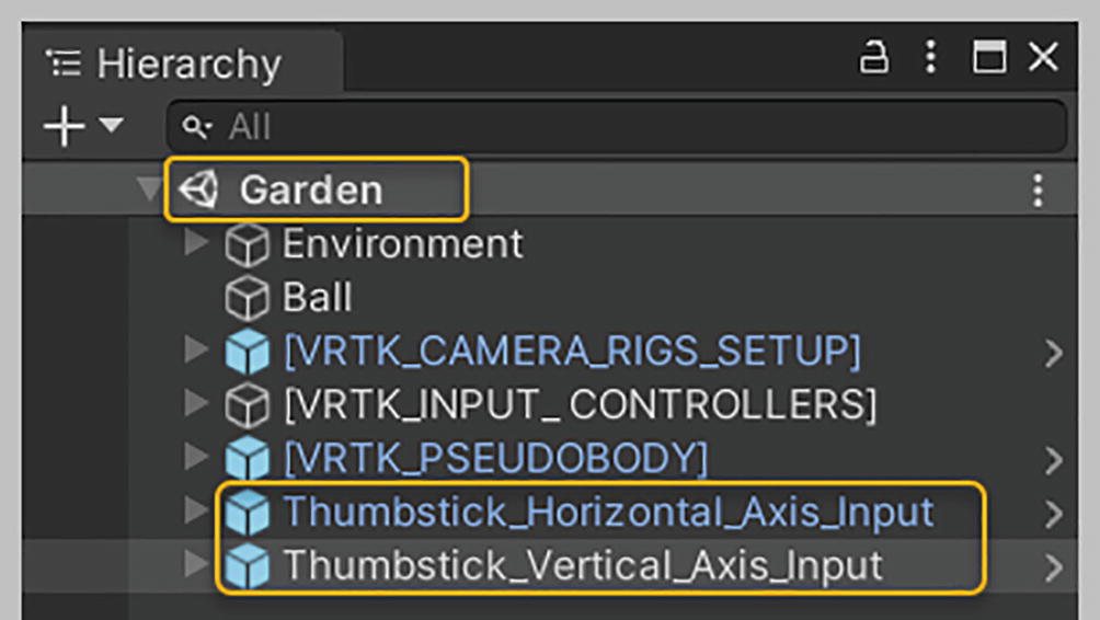
The Garden game object with its nested child game objects

Setting up the Activated event for the Thumbstick Horizontal Axis Input and Thumbstick Vertical Axis Input game objects
Next, in the “Packages” folder of the Project tab, locate the Tilia Locomotors Axis Move Unity package and expand its “Runtime/Prefabs” folder. Drag and drop the Locomotors Axis Move Vertical Slide Horizontal Snap Rotate prefab into the hierarchy, making it a child of the Garden game object.
Now, select the Locomotors Axis Move Vertical Slide Horizontal Snap Rotate game object in the hierarchy, and let’s set up its properties in the Inspector. Drag and drop the Thumbstick Horizontal Axis Input game object into the Horizontal Axis property of its Axis Move Facade component ; drag and drop the Thumbstick Vertical Axis Input game object into the Vertical Axis property of this component; drag and drop the Play Area Alias game object into its Target property ; drag and drop the Headset Alias game object into its Forward Offset property ; drag and drop in the Headset Origin game object into its Rotation Pivot property; and finally, Drag and drop the Scene Cameras game object into its Scene Cameras property .

Setting up the Locomotors Axis Move Vertical Slide Horizontal Snap Rotate game object
We now need to capture button input actions for the horizontal and vertical movements of our Right Controller’s Thumbstick. This will enable us to move the Ball in different directions during game play. We’ll capture these inputs for the Oculus and HTC Vive controllers.
To do this, with the Garden game object selected, let’s create a new empty game object in the hierarchy and rename this game object “Thumbstick Horizontal Axis Right.” Then, let’s add a Float Action component to this game object, and set its Sources size property to 2, which will provide you with two Element slots. Now, select the Thumbstick Horizontal Axis Right game object in the hierarchy, and duplicate it and rename the copied game object “Thumbstick Vertical Axis Right.”
Now, expand the VRTK INPUT CONTROLLERS game object in the hierarchy, and then expand the Input Unity Input Manager Oculus Touch Right Controller game object until you reach its Right Thumbstick game object, which you need to expand, too. You’ll be capturing input for the horizontal and vertical axis movement of the Right Thumbstick.
Next, expand the Input Unity Input Manager Open VR Right Controller game object until you reach its Right Trackpad game object, which you also need to expand. You’ll be capturing input for the horizontal and vertical axis movement of the Right Trackpad.
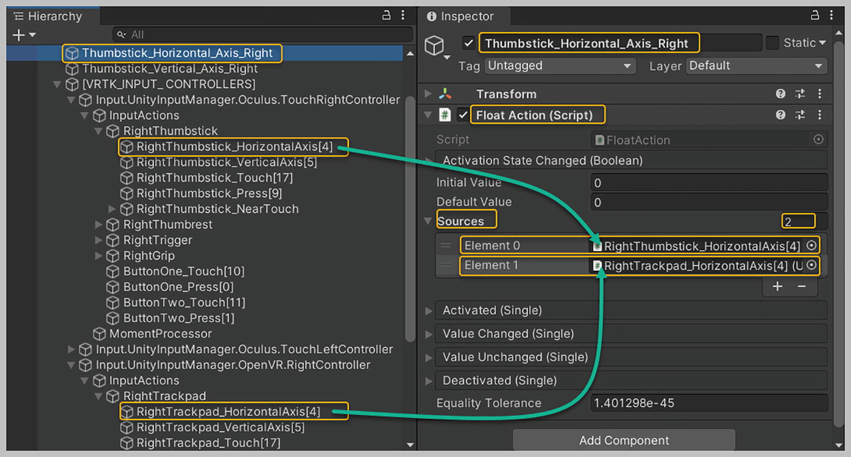
Setting up the Thumbstick Horizontal Axis Right intermediary game object
Now, in the hierarchy, select the Thumbstick Vertical Axis Right game object. Drag and drop the Right Thumbstick Vertical Axis [5] game object from the hierarchy into the Element 0 slot. Then, drag and drop the Right Trackpad Vertical Axis [5] game object into the Element 1 slot, see Figure 22-15.

Setting up the Thumbstick Vertical Axis Right intermediary game object
Enabling Obstacle Objects to Attach to the Ball
Upon rolling the Ball onto any obstacle game object in the Scene, you must ensure that the object attaches itself to the Ball. To achieve this behavior, we’ll set up a Mutators Object Follower. You’ll recall that we learned to use the Mutators Object Follower prefab when we had our Holsters follow our Play Area Alias. We also used the Offset Object property to offset the Holsters a bit in front of the Play Area. We’ll apply the same strategy here, with the Ball becoming the Source game object and each of the 37 obstacle game objects becoming a Target of the Mutators Object Follower prefab. Each of these 37 game objects contains a child Offset game object that has been assigned a random Transform Position value. Each child Offset game object with an assigned Transform Position value allows each obstacle game object to attach itself to the Ball in a slightly different position.
Let’s set this up now. Expand the “Packages” folder in the Project tab, locate the Tilia Mutators Object Follower Unity package, and expand it until you reach its “Prefabs” folder. Drag and drop the Mutators Object Follower prefab into the hierarchy, making it a child of the Garden game object, and rename the Mutators Object Follower game object, “Mutators Object Follower Obstacles.”

Setting up the Source game object (Ball) for Mutators Object Follower Obstacles
With the Mutators Object Follower Obstacles game object still selected in the hierarchy, set the Targets Elements property size to 37. This will provide you with 37 Element slots. Also, set the Target Offsets Elements property size to 37. This will provide you with 37 Element slots. Note that you now have 37 target obstacle game objects in the Scene. Each has its own Offset child game object.
You now need to populate all 37 Element slots with the obstacle game objects in the hierarchy. Note that you should only use the obstacle game objects that are activated, as those that are deactivated haven’t been configured with the necessary components. Twenty-three of these obstacle game objects are available as children of the Environment game object, and you can find the remaining 14 by navigating to Environment ➤ World ➤ Map Objects, see Figures 22-5 and 22-6 earlier in this chapter.

The Targets Elements List populated with the obstacle game objects

The Target Offsets Elements List populated with each obstacle game objects, nested Offset child game object
We now need to set up a Rule that defines which target obstacles will be considered ready to be attached to the Ball. You have assigned a Collision Tracker component to each obstacle game object in the Scene. Whenever the Ball collides with an obstacle, the Collision Started event in the Collision Tracker component for that specific obstacle gets triggered, setting the obstacle’s Tag to Grabbable.
The Rule that you’ll create as part of the Target Validity property of the Mutators Object Follower Obstacles game object will only allow an obstacle game object whose Tag is set to Grabbable to be attached to the Ball when the Ball collides with the obstacle. According to this Rule, when the Ball collides with an obstacle whose Tag is set to Grabbable, it will be attached to the Ball. It will then begin to follow the Ball using the Offset that was created.
Let’s set up this Rule now. In the hierarchy, with the Garden game object selected, create a new empty child game object and rename it “Attach Rule.” Select the Attach Rule game object, and in the Inspector, add two new components to it: the Any Tag Rule component and the String Observable List component . We’ve already used both of these components in Chapter 16, when we set up the Snap Zone Valid Tags rule game object in the Demo scene.

Setting up the Attach Rule game object

Setting up the Target Validity property to reference the Attach Rule that allows only game objects tagged as Grabbable to be attached to the Ball
The Attach Rule will now only allow any of the 37 listed target obstacle game objects to attach themselves to the Ball. The concerned obstacle Tag is set to Grabbable when the Ball collides with it, and it is then that the obstacle attaches itself to the Ball.
Getting the Ball to Roll About Freely
In this section, we’ll set up the Right Controller Thumbstick to control the Ball’s movement, wherein the player will be allowed to roll the Ball forward, backward, left, and right. The Left Controller Thumbstick is responsible for controlling the player’s movement and rotation.
To achieve realistic Ball movement, we’ll use a physics force against the Ball Rigidbody with the Input Combined Actions Axes to Vector 3 Action prefab . Attempting to achieve such realistic Ball movement without using this VRTK-provided prefab would require us to write math code involving Vectors and Trigonometry. But thanks to this VRTK prefab, we’re not required to write any such math code. Let’s begin setting this up now.
From within the Project tab, expand the “Packages” folder, locate the Tilia Input Combined Actions Unity package, and expand its “Prefabs” folder. Drag and drop the Input Combined Actions Axes to Vector 3 Action prefab into the hierarchy, making it a child of the Garden game object. With the Input Combined Actions Axes to Vector 3 Action game object selected in the hierarchy, ensure that its Axes to Vector 3 Action component has been expanded in the Inspector. Scroll down to the “Axis Settings” section, where you’ll need to set up some properties.
Locate the Lateral Axis property , and drag and drop the Thumbstick Horizontal Axis Right game object into this property parameter. The Lateral Axis (x axis) is responsible for capturing the left and right movement of the Thumbstick. You’ll recall that the Thumbstick Horizontal Axis Right returns a float value between -1 and 1 when you push your Thumbstick either left or right, see Figure 22-21.
Then, do the same for the Longitudinal Axis property , dragging and dropping the Thumbstick Vertical Axis Right game object into its property parameter. The Longitudinal Axis (z axis) captures the forward and backward movement of your Thumbstick. The Thumbstick Vertical Axis Right returns a float value between -1 and 1 when you push your Thumbstick either forward or backward, see Figure 22-21.
As these lateral and longitudinal axes values are too small to have any real impact on the movement and rotation of the Ball, we’ll use the Multiplier property in conjunction with the Time Multiplier property to obtain a vector value that will be applied as the force to the Balls Rigidbody. Set the X and Z values of the Multiplier property to 100. Leave its Y value at 1, as you haven’t specified anything for the Vertical Axis property since you don’t want your Ball moving up and down.
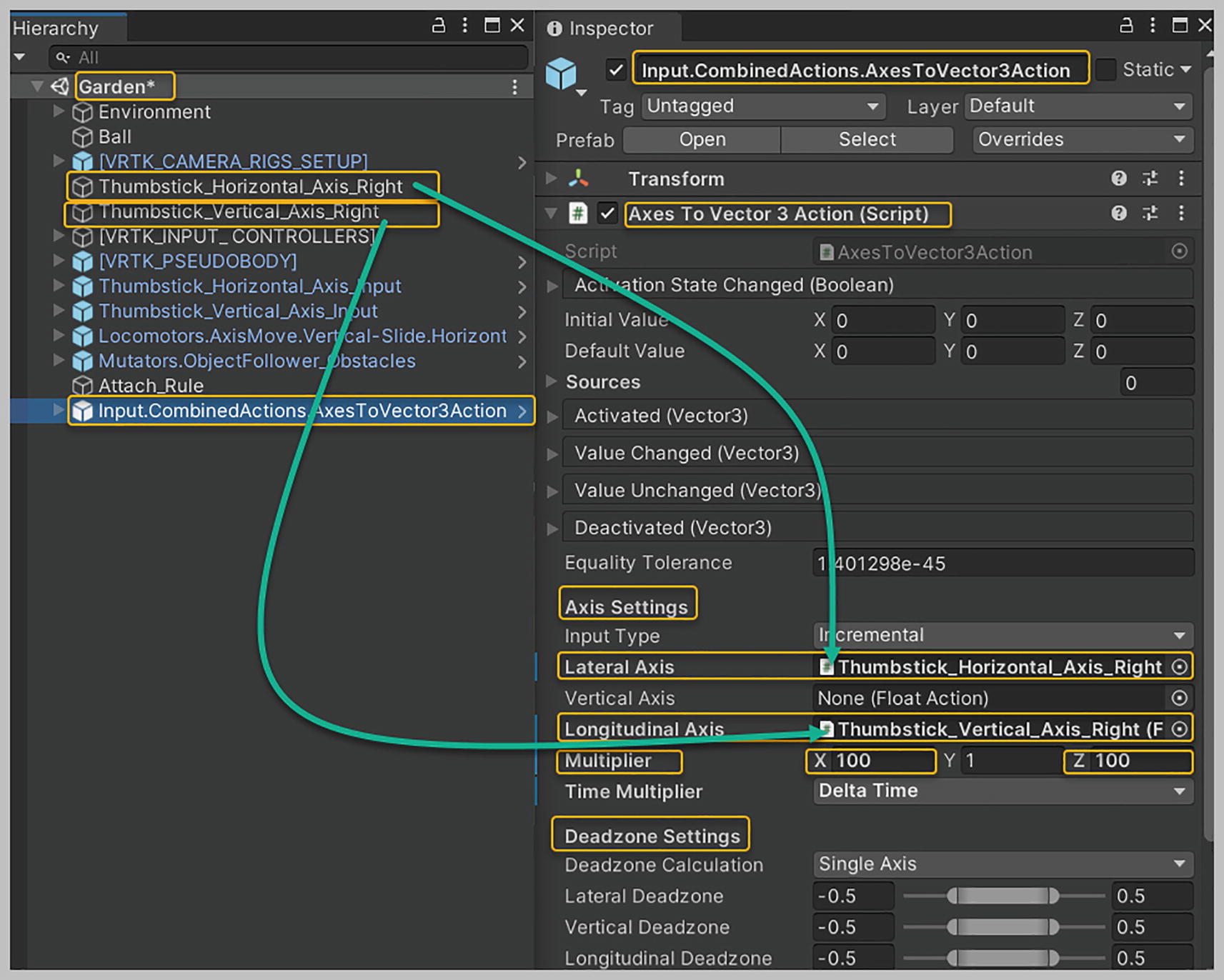
Setting up the Input Combined Actions Axes to Vector 3 Action
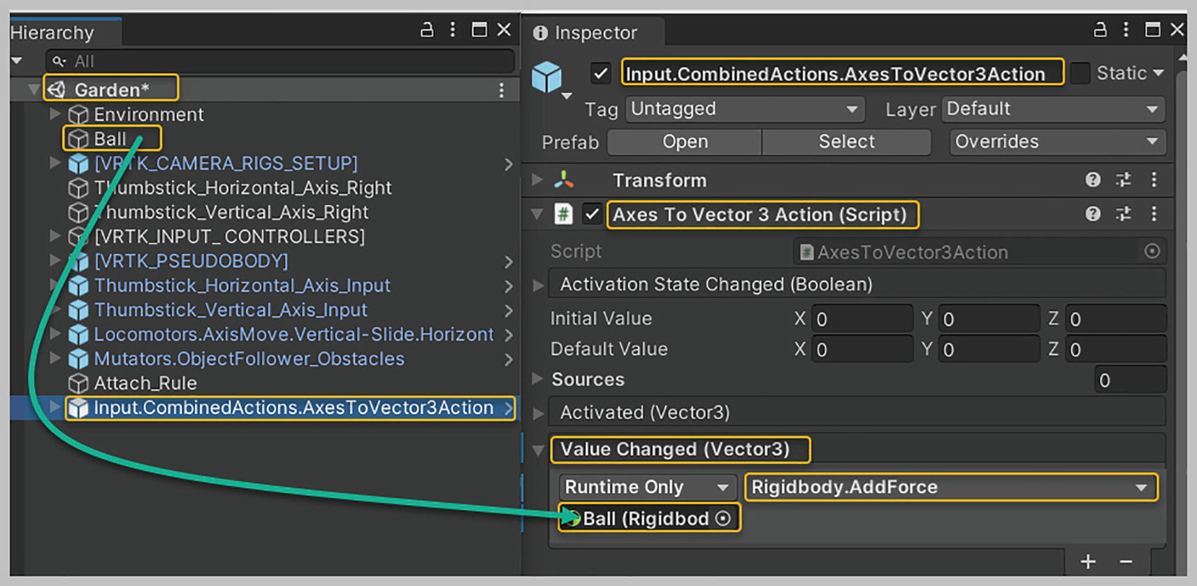
Setting up the Value Changed event
Using the Input Combined Actions Axes to Vector 3 Action, we’ve taken axis input data from our Thumbstick and converted it into movement and rotational information that the Ball can use. All the math involved in obtaining this information has been encapsulated into the VRTK’s Axes to Vector 3 Action component.
Now, playtest the scene using your VR headset and roll the Ball around. Note the fluidity of the Ball movement, as physics has been applied to it. Approach one of the obstacles, and roll the Ball onto it. You’ll see that it attaches itself to the Ball. We’re now able to collect obstacles in our game.
Spatial Tooltip to Display Countdown Timer
In this section, we’ll learn to set up a Countdown Timer for our minigame. This timer counts down the seconds you have left to complete the level, and upon the timer reaching zero, you’re no longer able to roll the Ball any further. This Countdown Timer will be displayed in the world using the Visuals Tooltip prefab provided by the VRTK. You could quickly write a Countdown Timer script yourself. The reason for setting up a Countdown Timer here is mainly to learn how to use the Moment Processor available with VRTK. Once you wrap your brain around this setup, you’ll find yourself using the Countdown Timer in several situations. Let’s begin.
First, let’s set up the Visuals Tooltip that will be used to display the Countdown Timer. You already learned how to set this up when you created the Slider and Snap Zone inventory slots.
From within the Projects tab, expand the “Packages” folder and locate the Tilia Visual’s Tooltip Unity package. Expand its “Prefabs” folder, and drag and drop the Visuals Tooltip prefab into the hierarchy, making it a child of the Garden game object. Rename this Visuals Tooltip game object “Visuals Tooltip Timer.”

Setting up the Visuals Tooltip Timer game object

Setting up the Transform Position and Rotation values for the Offset Tooltip game object
Now that our Visuals Tooltip Timer game object has been set up, we need to set up a Mutators Object Follower so that the Visuals Tooltip Timer game object can follow the Play Area Alias around at the given Offset distance. Let’s do this now.
Select the “Packages” folder in the Project tab, and locate the Tilia Mutators Object Follower Unity package and expand it until you reach its “Prefabs” folder. Drag and drop the Mutators Object Follower prefab into the hierarchy, making it a child of the Garden game object. Rename this Mutators Object Follower game object “Mutators Object Follower Tooltip.” With this game object selected in the hierarchy, ensure that its Object Follower component has been expanded in the Inspector. Set its Sources Elements property size to 1. This provides you with an Element 0 slot. Drag and drop the Play Area Alias game object from the hierarchy into this slot. The Play Area Alias is the Source Object that the Visuals Tooltip Timer game object will follow. Now, set the Targets Elements property size to 1. This provides you with an Element 0 slot. Drag and drop the Visuals Tooltip Timer game object into this slot. Next, set the Target Offsets Elements property size to 1. This provides you with an Element 0 slot. Drag and drop the Offset Tooltip game object into this 0 slot.

Setting up the Mutators Object Follower Tooltip game object to have the Visuals Tooltip Timer game object follow the Play Area Alias around at a predefined Offset distance
Setting Up the Countdown Timer and Moment Processor
The VRTK provides you with a Countdown Timer component that can be used to create a seconds countdown. Once this Countdown Timer reaches zero, you can perform an action. That action is to deactivate the Ball so that the player can no longer roll it farther. First, we’ll set up the Countdown Timer game object and then we’ll set up the two supporting objects needed to get a Moment Processor working. Let’s begin.
In the hierarchy, with the Garden game object selected, create a new empty game object and rename it “Timer.” Within the Inspector, add two new components to this Timer game object: Countdown Timer and Any Action .
With the Countdown Timer component expanded, set the Start Time property to 300 seconds. This allows the player five minutes to collect all obstacles in the level. You can adjust this Start Time property value to your liking, but note that its value should be in seconds.
Then, expand the Completed event, and click the plus symbol located in the bottom right corner to add a new event listener. Drag and drop the Ball game object into this event listener box. For this function, select Game Object, Set Active, and ensure that the check box below is left unchecked. This ensures that once your Countdown Timer has completed (i.e., reached 0), the Ball will be immediately deactivated and you’ll no longer be able to move the Ball any farther, as the time allotted to complete the level will have elapsed.
Next, expand the Remaining Time Emitted event, and click the plus symbol in the bottom right corner to add a new event listener. Drag and drop the Visuals Tooltip Timer game object into this event listener box. For thus function, select Tooltip Text, Show Tooltip from the “Dynamic Float” section, see Figure 22-26.
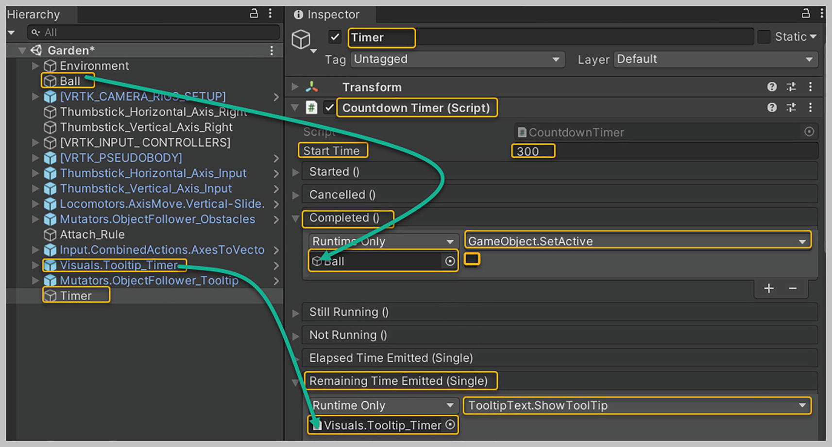
Setting up properties and events on the Countdown Timer component of the Timer game object
To get the Countdown Timer mechanism working, you first need to tell the Timer to begin counting down. You’ll start the Countdown Timer by calling its Begin method via the Any Action component’s Activated event. This component can be used to execute any possible action. Here, you’ll utilize it to execute the Countdown Timer’s Begin action.
For the Timer game object, ensure that the Any Action component has been expanded in the Inspector. To get the Countdown Timer to start counting down, expand the Activated event in the Any Action component and click the plus symbol in the bottom right corner to add a new event listener. Drag and drop the Timer game object from the hierarchy into this event listener box. For this function, select Countdown Timer, Begin from the “Static Parameters” section, see Figure 22-27.

Setting up the properties and events in the Any Action component of the Timer game object
Now that we’ve made the Countdown Timer functional, it needs to be polled repeatedly at a fixed interval—say, every half a second—so that at this given interval, the time remaining can be displayed via the Visuals Tooltip Timer game object. If you were writing your script, you could easily achieve this using Unity’s Update method. However, the VRTK provides you with a Moment Processor that functions like Unity’s Update method and can be used to call another Process repeatedly whenever a specific time interval has elapsed. We’ll use the Moment Processor to call the Countdown Timer Process after every half a second has elapsed. Let’s set up the Moment Processor game object first.

Dragging and dropping the Moment Process Observable List component into the None (Moment Process Observable List) text box as you set up the properties for the Moment Processor game object

Element 0 slot requiring a Moment process to be dropped in that will be processed on every Update
Let’s now set up a Moment Process that can be processed on every Update. In the hierarchy, with the Garden game object selected, create a new empty game object and rename it “Process Every Half Second.” With this game object selected in the hierarchy in the Inspector, add two new components: the Moment Process and the Event Process.
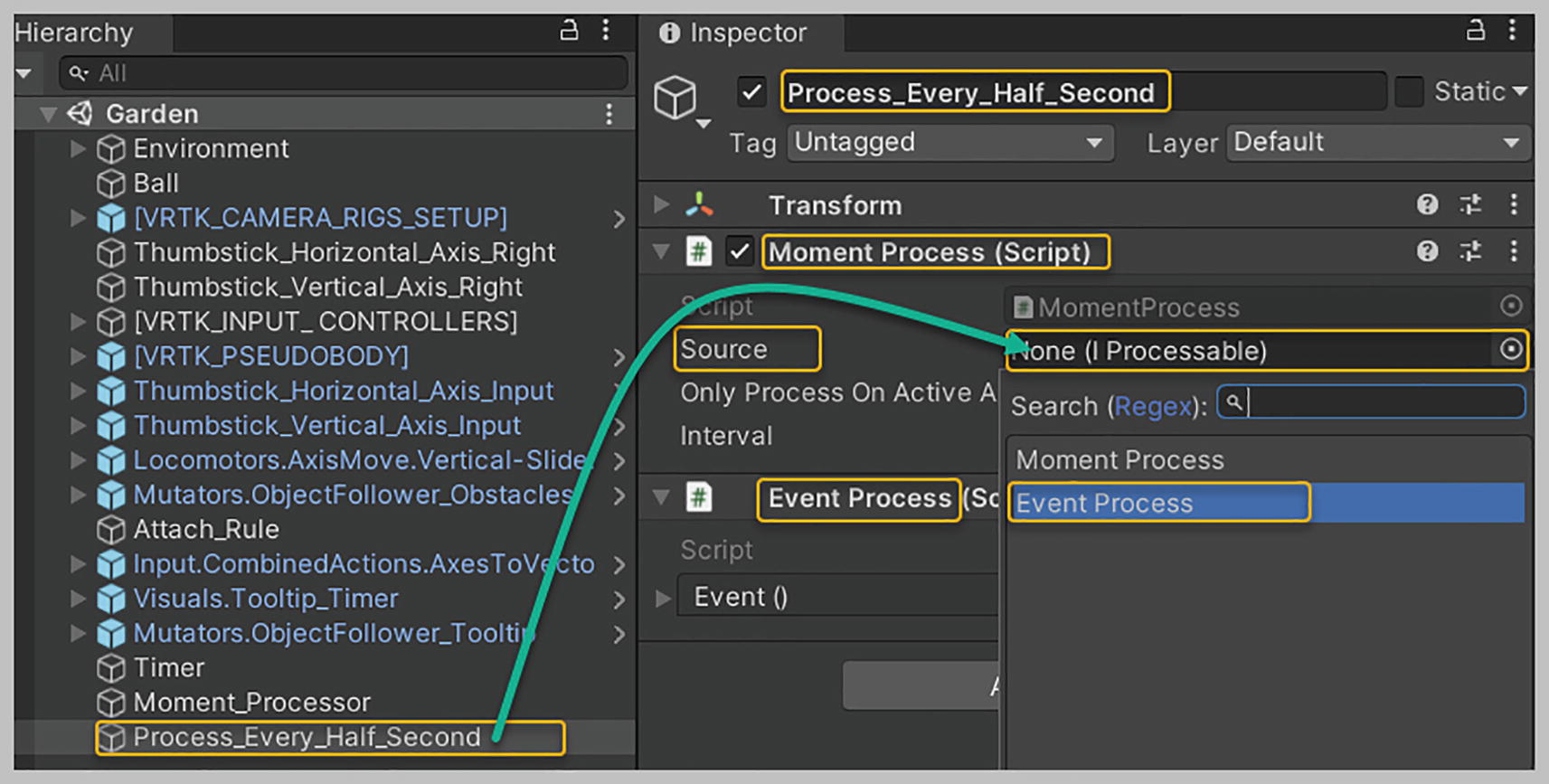
Dragging and dropping the Process Every Half Second Game object into the Source property of the Moment Process component presents a dialog box where you will select Event Process

Setting up Event () in the Event Process component
Last, select the Moment Processor game object in the hierarchy. In its Moment Processor component, locate Moment Process Observable List, Elements, Element 0 slot. Drag and drop the Process Every Half Second game object from the hierarchy into this slot.

Adding the Process Every Half Second Moment Process game object to the Moment Processor Moment Process Observable List, Elements, Element 0 slot
If you found setting up all these connections to be a mind bender, let me summarize how all the connections you hooked up and synced together got the Countdown Timer to work. Let’s start with the Moment Processor that runs processes assigned to it, every Update. Every Update, the Moment Processor will run the only Moment Process you have assigned—Process Every Half Second, see Figure 22-32.
The Process Every Half Second (Moment Process), shown in Figure 22-32, suggests that when it’s invoked, a half a second must have elapsed before it triggers the Event Process component’s Event () event . At that point, it will execute the Countdown Timer, Emit Remaining Time metho
The moment the Countdown Timer, Emit Remaining Time method is invoked, the Timer game objects, Remaining Time Emitted event will be triggered. The triggering of this event results in the Visuals Tooltip Timer game object displaying the floating-point value —or the time in seconds remaining as per the Countdown Timer—getting passed to it. Look back at Figure 22-26.

The Countdown Timer’s process workflow
Enhancing the Minigame
Increase the Ball scale factor by 0.1 every time the player attaches an obstacle to it.
Set up a Game Manager to keep count of the number of obstacles collected. Once a certain number of obstacles have accumulated, or the Ball has attained a specific size, the player can progress to the next level.
Use another Tooltip that displays an incremental count of the number of obstacles being attached to the Ball.
Assign categories to the obstacles, such as small, medium, and large, and then ensure that a certain number of small obstacles have been attached before allowing the player to capture the medium- and larger-sized obstacles.
Add some sound effects, preferably different types, for the different unique obstacle game objects attached to the Ball.
Add an overall musical theme to the game.
Summary
In the final chapter of this book, we have created a minigame without writing a single line of code, using several mechanics we learned about throughout the book. We learned how to create a Countdown Timer and set up a Moment Processor. We also learned to use a critical VRTK prefab, Input Combined Actions Axes to Vector 3 Action, to roll the Ball around by adding force to its Rigidbody, thereby avoiding the need to write math code involving Vectors and Trigonometry. We used the Collision Tracker component to set up Source, Targets, and Target Offset game objects that allowed obstacle game objects to attach themselves to the Ball. We set up a Spatial Tooltip to display the game’s Countdown Timer. We utilized the VRTK-provided Countdown Timer to count down time in seconds, ensuring that once the timer reaches zero, the game ends and the player isn’t allowed to move the Ball any farther. You learned to set up the Input Combined Actions Axes to Vector 3 Action prefab to allow the player to move the Ball realistically around the garden path. You also learned about the Countdown Timer’s Completed and Remaining Time Emitted events. In the last section of the chapter, we set up a Moment Processor and used its Update process moment to call another Process repeatedly whenever a specific time interval has elapsed. Along the way, we became familiar with how to use the Moment Process and Event Process components. We wrapped up the chapter by testing our minigame using our VR headset and, finally, were provided some tips on enhancing this minigame by adding some simple mechanics.