
In this chapter, we’ll get to know the Angular Drive prefab provided in the VRTK. We’ll also implement three common examples of its use. In the process, you’ll create a Steering Wheel, a Door, and a Lever. Angular Transform Drives and Angular Joint Drives can be thought of as controllable mechanisms that provide you with both physics- and nonphysics-based angular Interactable controls that can be used with a wide variety of game objects. Ideally, you’ll want to use the nonphysics-based linear/angular Transform Drive prefabs wherever possible, as the physics-based linear/angular Joint Drives rely heavily on Unity’s joints. If you intend to build multiplayer games, it’s best to keep joints to their bare minimum.
Setting Up a Steering Wheel
We’ll start our exploration of Angular Joint Drives by setting up a Steering Wheel in VR that you can rotate around using your hands. A Steering Wheel can be created using an Angular Transform Drive prefab. The Steering Wheel will rotate around a central hinge point. Whenever the item’s Angular Transform Drive value changes, an event can be triggered notifying the car’s axle of the change in value. The car’s wheels could then be aligned accordingly.
Let’s begin setting up this Steering Wheel game object. As one of the features available to download with this book, you’ve been provided with a Unity package file named “Steering Wheel.” This package file contains a prefab that comprises a Mesh for your Steering Wheel and a Box Collider that’s already been set up.
To begin the setup, download the “Steering Wheel” Unity package file and import it into your project. Once imported, you’ll have access to the Steering Wheel prefab in the “Assets” folder. If you open this prefab, you’ll see that it comprises a Steering Wheel mesh, a couple of materials, and a Box Collider. Select and expand the Environment game object in the hierarchy, and create a new empty child object and rename it “Steering Wheel.” Your Steering Wheel will be placed on top of your worktable. Select the Steering Wheel game object in the hierarchy and set its Transform Position values as follows: X = -11.94; Y = 0.775; and Z = -4.33. Note that you won’t see the Steering Wheel yet, as it still isn’t hooked up.
Next, select the “Packages” folder in the Project tab and expand it until you reach the Tilia Interactions Controllables Unity package. Then, expand it further until your reach its Prefabs, Transform folder. Then, drag and drop the Interactions Angular Transform Drive onto the Steering Wheel game object in the hierarchy. A large white cube will now be sitting on your worktable, and you’ll soon replace this cube mesh with a Steering Wheel mesh.
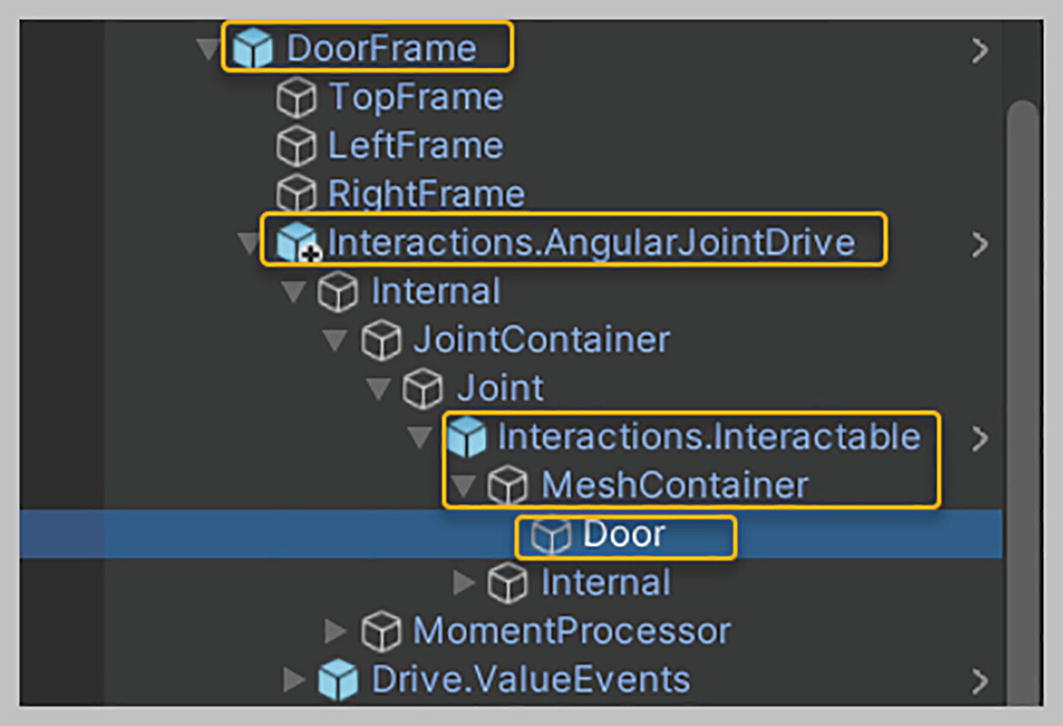
Now, expand the Interactions Angular Transform Drive in the hierarchy until you reach its Interactions Interactable game object and then expand that, too. You can reach this Interactions Interactable game object by navigating as follows: Internal ➤ Interactable Container ➤ Interactions Interactable, see Figure 19-1.
You’ll see that Interactions Interactable game object contains a Mesh Container game object, which in turn holds your white cube that needs to be replaced with the Steering Wheel. Note that by nesting the Interactions Interactable game object in the Interactions Angular Transform Drive, you’ve been automatically provided the ability to interact with its Mesh without having to explicitly add an Interactable game object yourself.
Select the Interactions Interactable child game object in the hierarchy and look at its Interactable Facade component in the Inspector. Locate its Follow Tracking property and note that it has been set to Follow Transform Position Difference Rotate. This property setting is what allows you to rotate your Steering Wheel around smoothly, see Figure 19-1.
Now, select the Cube child game object in the Mesh Container game object, as shown in Figure 19-1, and deactivate it. Next, drag and drop the Steering Wheel prefab from your “Assets” folder onto the Mesh Container game object, making it a child. If you look at your worktable now, there will be a Steering Wheel sitting on it.

Accessing the Interactions Interactable game object, noting the setting for its Follow Tracking property

Setting the Drive Axis property of the Steering Wheel sitting on top of the table to the Y Axis

Upward-pointing green y axis around which the Steering Wheel will rotate. The dual-facing dashed arrow indicates the directions in which the Steering Wheel can rotate
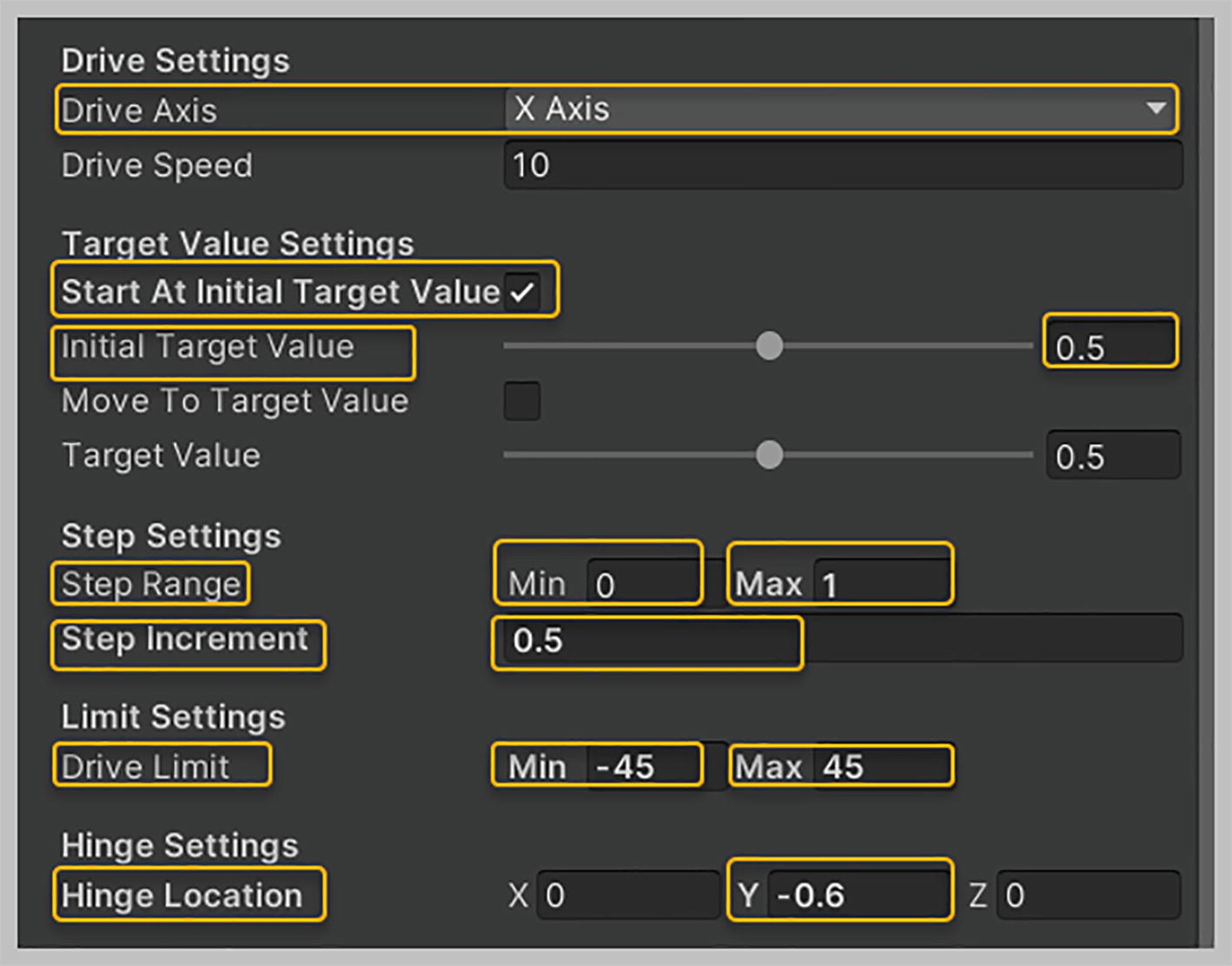
All the other properties in the Angular Drive Facade component of the Interactions Angular Transform Drive game object can be left at their default values. One important property to note is the Drive Limit, whose minimum and maximum values have been set to -180 and 180 by default. Having the Drive Limit property set to these values ensures that you can’t turn your Steering Wheel a full 360 degrees, but only 180 degrees (i.e., in a semicircle). That’s all the setup required to use your Steering Wheel.
Now, playtest the Demo scene using your VR headset. Note that you can grab your Steering Wheel and smoothly spin it around. Also note that it won’t spin beyond 180 degrees when being turned either left or right. You can efficiently perform a Snap Grab action with either hand against your Steering Wheel, thanks to the Secondary Action property setup on the Interactions Interactable, which has been set to Interactable Grab Action Swap.
Before setting up a Door in the next section, let’s set the Layer for the Steering Wheel game object to Interactable. Select the Steering Wheel game object in the hierarchy, and in the Layer drop-down of the Inspector, select the value Interactable. When asked whether to also set the Layer to Interactable for all child objects, select the button Yes, Change Children. Last, disable your Holsters game object.
Setting Up a Door
In this section, we’ll create a Door that will rotate around a given hinge point on its frame. Doing this allows us to simulate a Door that can be opened and closed. To set up this mechanism, you’ll use an Angular Joint Drive prefab that uses Unity joints. Along the way, you’ll also learn about a new VRTK prefab, the Collision Ignorer.
As part of downloads available with this book, you were provided a Unity package file named “Door and Frame.” It contains one prefab: a Door Frame and a single Door model (an .FBX file). Download this “Door and Frame” package file and import it into your project. Once imported, you’ll have access to the Door Frame and the single Door prefab as an .FBX file in the “Assets” folder. This prefab has been created using three unity cube objects, resizing them appropriately, and setting up their position. These settings ensure that the Door aligns within the Door Frame well. A simple dark-brown wood material has been applied to this Door Frame.
Let’s begin by setting up the Door Frame. Select and expand the Environment game object in the hierarchy. Then, drag and drop the Door Frame prefab from the “Assets” folder onto the Environment game object in the hierarchy, making it a child. Note that your Door Frame has been positioned beside your Tool Holders. Expand this Door Frame game object in the hierarchy, and you’ll see that it contains three cubes representing the top, left, and right frames that make up your Door Frame.
Next, expand the “Packages” folder in your Project tab, locate the Tilia Interactions Controllables Unity package, and expand it until you reach its “Prefabs” folder. This time around, select and expand the “Physics Joint” folder. Now, drag and drop the Interactions Angular Joint Drive prefab onto the Door Frame game object in the hierarchy, making it a child. You’ll notice that a giant white cube has filled your Door Frame.
Locating the Cube game object in the Interactions Angular Joint Drive and renaming it “Door”

Populating the Mesh Filter and Mesh Renderer properties to have the Door displayed instead of the white cube
In the Inspector, with the Door game object still selected in the hierarchy, set its Transform Position property values as follows: X = 0.453; Y = 0.17; and Z = -0.028. Then, set its Transform Rotation property values to X = -90; Y = 0; and Z = 0. Last, ensure that the Transform Scale property values for X, Y, and Z are set to 1. You’ll notice that the Door now fits in its Door Frame perfectly, see Figure 19-6.
With the Door game object still selected, expand its Box Collider component and click the Edit Collider button in it. You’ll see that the Box Collider for the Door game object isn’t even close to encompassing the entire Door; you need to ensure that it encompasses the Door completely. You could go about adjusting this yourself, but it would be quite tedious, so I’ll provide you with the values that would make for a suitable fit.

Setting up the property values for the Transform and Box Collider components of the Door game object

Setting up property values in the Angular Drive Facade component of the Interactions Angular Joint Drive game object
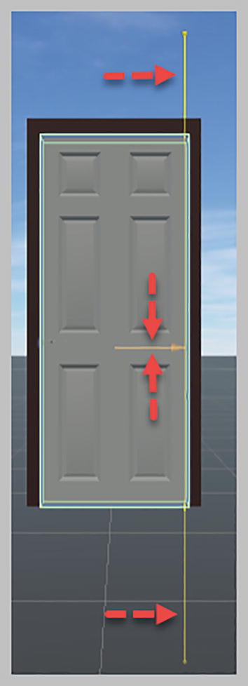
The Gizmo Line Distance property showing a thin vertical line passing through the right Door Frame, representing the y axis that the Door will rotate around
If your Door has its Handle located next to the right Door Frame, you’ll need to hinge your Door against the left Door Frame. In this case, your Hinge Location X value would need to be set to -0.45, as the Transform Position X value of the Door’s Left Frame game object is equal to -0.5. It’s essential to keep this concept in mind when working with Doors that have a Handle.
Playtesting your Demo scene at this point will result in the Door being hurled away into the stratosphere. This is on account of the Box Collider on the Door colliding with the Box Colliders on the Door Frame. You could use the Layer Collision Matrix to avoid these colliders from colliding with each other. However, the VRTK provides you with a Collision Ignorer prefab, which you can use to have all the colliders on the Door Frame ignore the collider on the Door. Let’s set this up now.
Expand the “Packages” folder in the Projects tab and locate the Tilia Mutators Collision Ignorer Unity package. Expand it until you reach its “Prefabs” folder. Drag and drop the Mutators Collision Ignorer prefab onto the Door Frame game object in the hierarchy, making a child of it. Select this Mutators Collision Ignorer game object in the hierarchy, and ensure that its Collision Ignorer component has been expanded in the Inspector. Set its Sources Elements size property value to 3. This will provide you with three element slots. Drag and drop the Top Frame game object from within the Door Frame game object in the hierarchy into the Element 0 slot. Then, drag and drop the Left Frame game object into the Element 1 slot. After that, drag and drop the Right Frame game object into the Element 2 slot, see Figure 19-9.
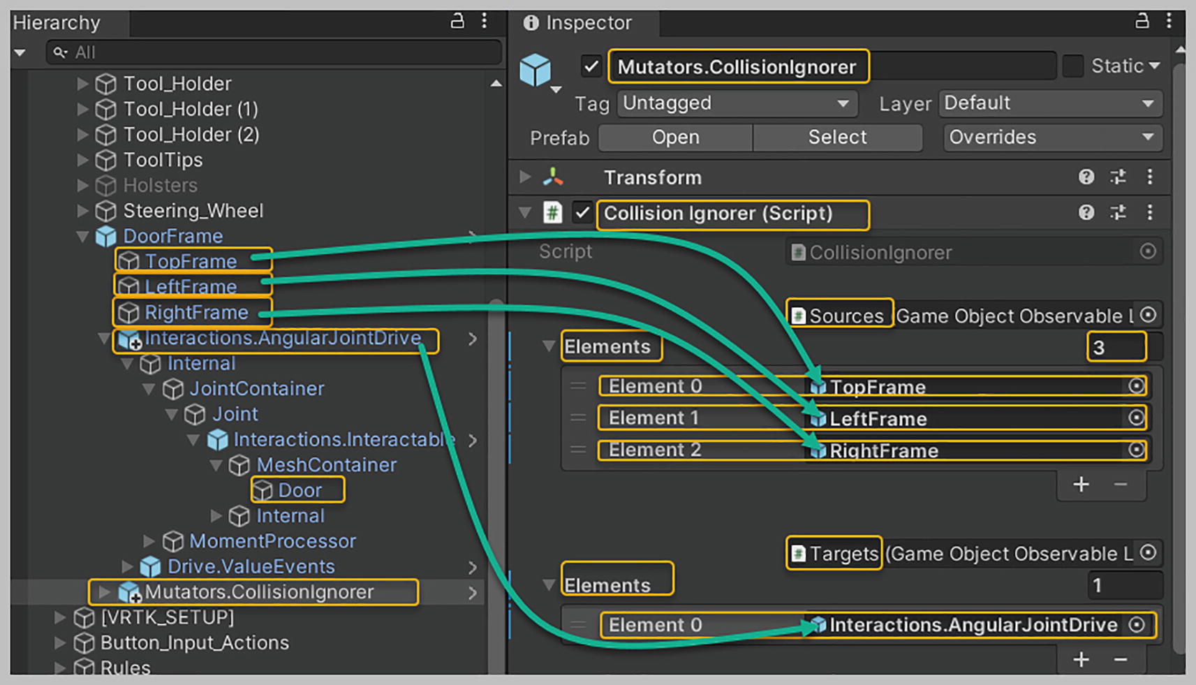
Setting up property values for the Mutators Collision Ignorer game object
Now, playtest the Demo scene using your VR headset. Walk up to the Door and either pull or push it to open it. You’ll notice that doing either of these things won’t force the Door past the Min and Max rotation values that you set as part of its Drive Limit property.
Under normal conditions, you would want a Door that when pushed or pulled would move only until it gets to its closed position and then remain shut. Most real doors don’t revolve past their closed position and can only be opened and shut from one side. We’ll now configure the Door further so that reproduces these conditions, so that will be more realistic to how a door actually works.

Choosing properties in Target Value Settings that ensure that the Door is shut at scene startup

Setting up properties within the Step Settings section
Next, we need to set up the Started Moving event, which is fired whenever your Door starts moving as a result of pulling or pushing it. Within the Angular Drive Facade component of the Interactions Angular Joint Drive game object, locate and expand the Started Moving event. Click the plus symbol located in the bottom right corner of this event to create an event listener. Drag and drop the Interactions Angular Joint Drive game object from the hierarchy into the event listener box of this event.
For the function, select Angular Drive Facade, and in the context menu that appears, select Set Drive Limit Maximum from the “Static Parameters” section. Set the value for this function’s parameter to 0. This ensures that whenever the Door starts moving after you pull or push it, its Drive Limit Max value will immediately be set to 0, according to which the Door will now revolve only between its Drive Limit Min value of -120 degrees and its newly set Drive Limit Max value of 0 degrees. It will stop at this zero-degree Drive Limit Max value, which represents the Door being in the shut position, see Figure 19-12.

Setting up the Started Moving event to ensure that when the Door is pulled or pushed, it doesn’t move beyond its shut position
Playtest your Demo scene using your VR headset. Approach the Door, which is currently in a closed position, and pull its Handle to open it. With your Door open, push it to slam it shut. Note that your Door no longer goes past its closed state. Now, approach the Door from the opposite side, and grab its Handle and attempt to pull it open. You’ll find that it can’t be pulled open from the other side. Simply push the Door and you’ll see that it swings open.
You now have a Door that can be opened and closed realistically.
Setting Up a Lever
In this section, we’ll create a Lever that will rotate around an x axis hinge point. We’ll use an Angular Joint Drive prefab to set this up. One everyday use of a Lever would be for a gearbox within a car. As part of the downloads for this book, you were provided a Unity package file named “Lever” containing a VR Lever prefab. Download the “Lever” file and import it into your project. After you’re done, you’ll have access to the VR Lever prefab in the “Assets” folder.
Select and expand the “Environment” folder in the hierarchy. Then, from within the “Assets” folder, drag and drop the VR Lever prefab onto the Environment game object in the hierarchy, making it a child. Note that a Lever has been positioned on your worktable. Select this VR Lever game object in the hierarchy, right-click it, and then select Prefab, Unpack Completely from the context menu that pops up. Expand this VR Lever game object in the hierarchy, and you’ll see that it contains two child game objects, a Handle and a Container. The Handle represents a lever that can be grabbed and moved forward and backward, while the Container represents the gearbox within which the Handle sits.
Expand the “Packages” folder in the Project tab, locate the Tilia Interactions Controllables Unity package, expand it until you reach its “Prefabs” folder, and then select the “Physics Joint” folder. Now, drag and drop the Interactions Angular Joint Drive prefab onto the VR Lever game object in the hierarchy, making it a child. You’ll notice that a large white cube has encompassed your VR Lever.
With your VR Lever game object expanded, select the Interactions Angular Joint Drive and expand it until you reach its Mesh Container. Expand this Mesh Container game object until you can see its child Cube game object and deactivate it. Drag and drop the Handle game object onto the Mesh Container, making it a child. Select this game object, and ensure that its Transform Position property values for X, Y, and Z are set to 0. Make sure that its Transform Rotation property values for X, Y, and Z are also set to 0. Leave the Transform Scale property values at their default. Last, set the Layer for this Handle game object to Interactable and apply this Interactable Layer to its child objects as well when prompted.

Setting up the Transform Position Y value for the Lever Handle
Within the Angular Drive Facade component, ensure that the Drive Axis property is set to X Axis, as your Lever needs to rotate around its x axis. Then, check the Start At Initial Target Value box and set the Initial Target Value property to 0.5. This will ensure that your Lever is centered within its gearbox container at the start. Set the Step Range Min value to 0 and the Step Range Max value to 1. Set the Step Increment property to 0.5.
It’s not required that you set up these values. However, doing do will be helpful if you plan to use some of the available events to pass these values across to other components. In the “Limit Settings” section, set the Drive Limit Min property value to -45 and the Drive Limit Max property value to 45.
Last, you need to set the Hinge Location property value to -0.6. This ensures that the hinge is placed at the bottom of the Lever rod, see Figure 19-14.
Setting up property values in the Angular Drive Facade component of the Interactions Angular Transform Drive game object
Last, let’s add a Collision Ignorer component to the VR Lever so that collisions between the VR Lever Container game object and the VR Lever Handle, which resides in the Interactions Angular Transform Drive, are ignored. Expand the “Packages” folder in the Projects tab, locate the Tilia Mutators Collision Ignorer Unity package, and expand it until you reach its “Prefabs” folder. Then, drag and drop the Mutators Collision Ignorer prefab onto the VR Lever game object in the hierarchy, making a child of it. Select this Mutators Collision Ignorer game object in the hierarchy and ensure that its Collision Ignorer component has been expanded in the Inspector. Set its Sources Elements size property value to 5, which will provide you with five element slots. In the hierarchy, expand the Container game object, a child of the VR Lever. Drag and drop each Base game object into each of these element slots, see Figure 19-15.
Within this Collision Ignorer component, under Targets, set the Elements size property value to 1, and you’ll be provided with an Element 0 slot. Drag and drop the Interactions Angular Joint Drive game object from the hierarchy into this 0 slot, as shown in Figure 19-15. The Collision Ignorer setup now ensures that your Targets, Handle collider will no longer collide with the Source, VR Lever Container colliders.

Setting up property values for the Mutators Collision Ignorer game object
Playtest the Demo scene using your VR headset. Approach the Lever and note that its is centered in your gearbox at the start. Grab the Lever knob and push it forward to see it rotate forward smoothly. Now pull on the Lever knob, drawing it back. Note that it stays within the Drive Limits setup.
While playtesting the Demo scene, you might have noticed that the Lever at times continues to move upon being released. This behavior is ideally not something you would want to have happen. It’s an uncalled-for action that happens because of the Rigidbody, Angular Drag value being set too low. Let’s fix this now.
From within the VR Lever game object, select the Interactions Angular Joint Drive, and from within that, select Interactions Interactable. Now, in the Interactable Facade component of the Inspector, locate the Last Ungrabbed event and expand it. Note that within its event listener box for the function Rigidbody, Angular Drag, the parameter value has been set to 0.01 by default. This Angular Drag value is minimal, which causes not enough angular Drag to be applied to the Lever to stop it from moving. Change this value to 5000 or any other large value.

Increasing the Angular Drag Value to 5000 in the Last Ungrabbed event

The Gizmo Line Distance property showing a thin horizontal line that represents the X axis that the Lever will pitch around
Angular Joint Drive and Logic Objects
In this section, we’ll take a deep dive into the Interactions Angular Joint Drive and examine some of its Internal events that might be helpful when building your game or application. We’ll look at the Minimum Reached, Midpoint Reached, and Maximum Reached event objects. These events are triggered when the Target Value property in the Angular Drive Facade component of the Interactions Angular Joint Drive reaches either its Minimum, Midpoint, or Maximum value. To see these events in action, we’ll create some Lever logic, wherein your Lever will initially be allowed to rotate from its central position in a forward direction only, allowing you to push it forward and pull it back. However, when pulled back, it will rotate back to its central position only. We’ll then set up the Lever so that it rotates between its central position in a reverse direction only, so that you may pull the Lever back. However, upon attempting to push it forward, it will rotate only to its central position. Finally, we’ll set up the Lever to work like it does in automatic transmission for a car and allow the Lever to be moved between three positions: forward (drive), central (neutral), and backward (in reverse). To verify that the appropriate events are being called, we’ll examine the Min and Max values for the Dive Limit . Let’s begin setting this up.
First, select the VR Lever game object in the hierarchy, and set its Transform Rotation Y value to 0. This ensures that moving the Lever forward 45 degrees represents the Lever in its forward/drive, fully rotated state; moving it 0 degrees represents the Lever in its central/neutral position; and moving it back 45 degrees represents the Lever in its backward/reverse, fully rotated state.
Then, with the VR Lever game object selected in the hierarchy, expand the Interactions Angular Joint Drive and Drive Value events. In these events, expand both Event Outputs and Internal In Event Outputs, and you’ll find the Minimum Reached, Midpoint Reached, and Maximum Reached event objects, using which you’ll hook up your Lever logic. The Maximum Reached event is triggered when the Target Value property reaches a value of 1, representing the Lever in its forward/drive state. The Midpoint Reached event is triggered when the Target Value property reaches a value of 0.5, representing the Lever in its central/neutral position. The Minimum Reached event is triggered when the Target Value property reaches a value of 0, representing the Lever in its backward/reverse state. The Lever will start in the central/neutral position, with its Drive Limit values set to Min = -45 and Max = 45.
The first piece of Lever logic we’ll set up will only allow the Lever to rotate from its central position forward and vice versa. To achieve this, you need to ensure that during runtime, when the Maximum Reached event is triggered, the Drive Limit Min value to is set to 0 and Drive Limit Max value is set to 45. This will ensure that the Drive can rotate 45 degrees forward from its central position. By setting the Drive Limit Min value to 0, you have ensured that it will only rotate to its central position when you pull back on the Lever Handle.
Let’s implement this logic now. Select the VR Lever game object in the hierarchy, and create a new empty child game object and rename it “Lever Logic.” Then, select this Lever Logic game object, and create a new empty child game object and rename it “Lever Max Reached.” Select this Lever Max Reached game object in the hierarchy, and in the Inspector, add a new component, Empty Event Proxy Emitter. Expand this Emitted event and click the plus symbol in its bottom right corner twice to add two event listeners. Now, drag and drop the Interactions Angular Joint Drive game object into both of these event listener boxes.
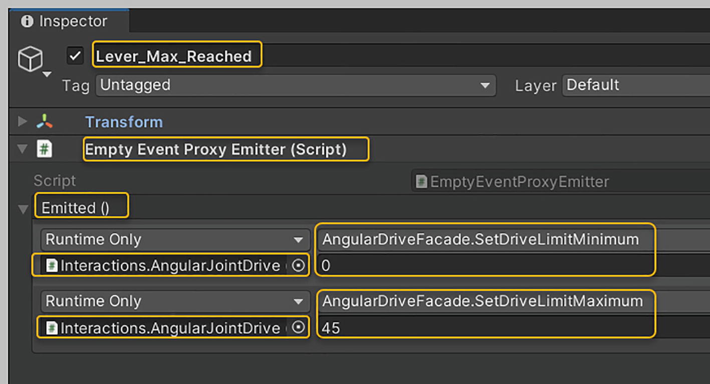
Setting up the Empty Event Proxy Emitter component on the Lever Max Reached game object
When your Lever Max Reached, Empty Event Proxy Emitter is invoked via the Maximum Reached event, the logic you’ve set up will ensure that your Lever will only be able to rotate between its central and forward positions. Note that the VRTK has allowed you to place your logic in a game object, which does away with the necessity of writing code.
Now you need to hook up the Lever Max Reached game object to the Maximum Reached event. Select the Maximum Reached event in the hierarchy. In the Inspector, locate and expand its Activated (Boolean) event. Click the plus symbol located in the bottom right corner of this event to add an event listener. Now, drag and drop the Lever Max Reached game object into this event listener box. For the function, select Empty Event Proxy Emitter Receive from within the “Static Parameters” section, see Figure 19-19.
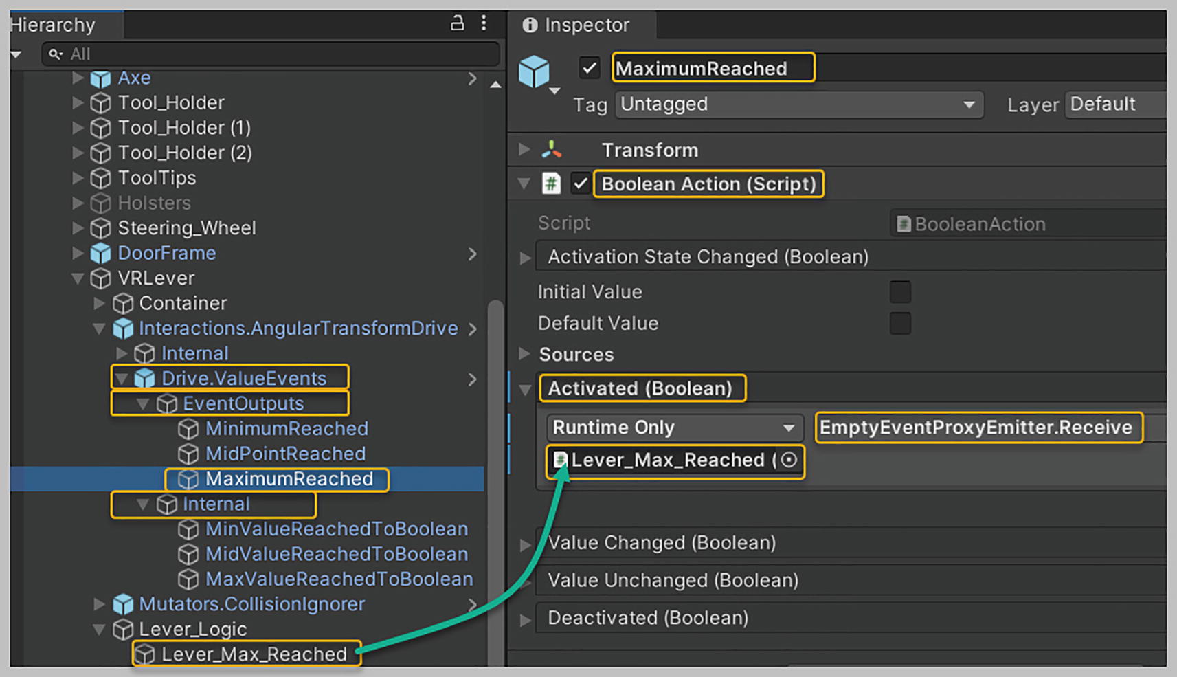
Setting up the Maximum Reached event to invoke the Lever Max Reached logic object
Now let’s work on setting up the second phase of Lever logic, where we’ll allow our Lever to rotate from its central position in a reverse direction. When pushed forward from its reversed position, it will rotate forward to its central position only. To achieve this, you need to ensure that when the Minimum Reached event is triggered, the Min and Max Values for the Drive Limit are set to -45 and 0. This will guarantee that the Drive can rotate in reverse from its central position to -45 degrees. Also, by setting the Drive Limit Max value to 0, you have ensured that when you push the Lever forward from its reversed position, it will rotate only up to its Max value 0, which is its central position.
The overall steps we’ll follow to implement this second phase of Lever logic are like those we performed when setting up the Lever Max Reached logic. However, the logic that will be built into a new Lever logic game object will be different, and the event we’ll now use to invoke this logic is the Minimum Reached event. Let’s implement this logic now.
Select the Lever Logic game object in the hierarchy, and create a new empty child game object in it and rename it “Lever Min Reached.” Select this child game object in the hierarchy, and in the Inspector, add a new component to it called Empty Event Proxy Emitter. Expand its Emitted event, and click the plus symbol located in its bottom right corner twice to add two event listeners. Now, drag and drop the Interactions Angular Joint Drive game object into both of these event listener boxes.
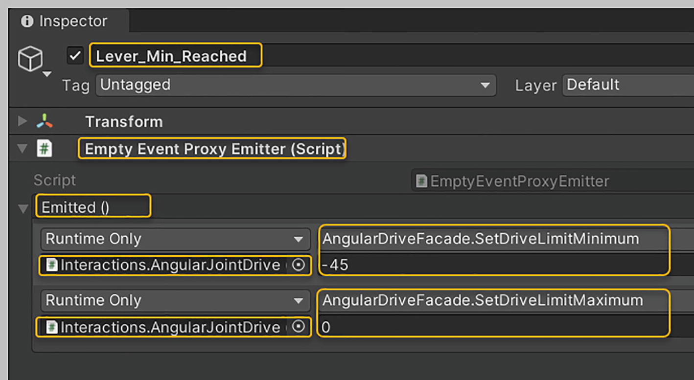
Setting up the Empty Event Proxy Emitter component on the Lever Min Reached game object
When your Lever Min Reached, Empty Event Proxy Emitter is invoked via the Minimum Reached event, the logic you have set up will ensure that your Lever will only be able to rotate between its central and rearmost positions. Note how the VRTK allows you to place your logic in a game object, doing away with the necessity of writing code.
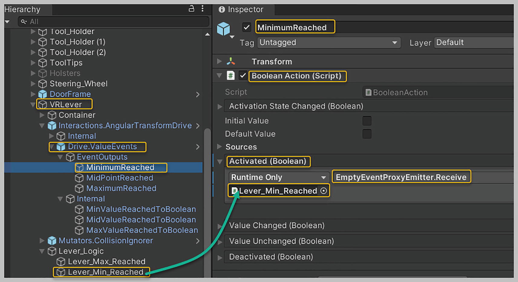
Setting up the Minimum Reached event to invoke the Lever Min Reached logic object
You’ve now ensured that after you pull your Lever back, as soon as its Target Value property reaches 0, the Minimum Reached event will be triggered. This, in turn, will invoke the logic you’ve built in the Lever Min Reached game object. The Min and Max values for your Drive Limit are set appropriately when this Lever Min Reached logic is executed, allowing the Lever to rotate only between its central and rearmost positions.
Before testing the Demo scene, we may need to tweak some essential values for triggering the Minimum, Maximum, and Midpoint reached events. I have noted that the positive bounds limits set up by default, which are essential to triggering events previously discussed, may need some tweaking with my testing. With their default values, they do not trigger events appropriately. I have gone through a trial-and-error phase of tweaking these numbers to get these events to work well with my Oculus Quest. If you find the default values aren’t working out well with your own testing, I’d suggest updating these values.

Tweaking the Min and Max values of the Positive Bounds property for the Min Value Reached to Boolean game object
Now when the Target Value is anywhere between 0 and 0.1, it will be considered that the minimum value has been reached. I personally found the default value settings too close in number, due to which the minimum value was rarely reached. As a result, the Min Reached event would be triggered only occasionally.

Tweaking the Min and Max values of the Positive Bounds property for the Mid Value Reached to Boolean game object
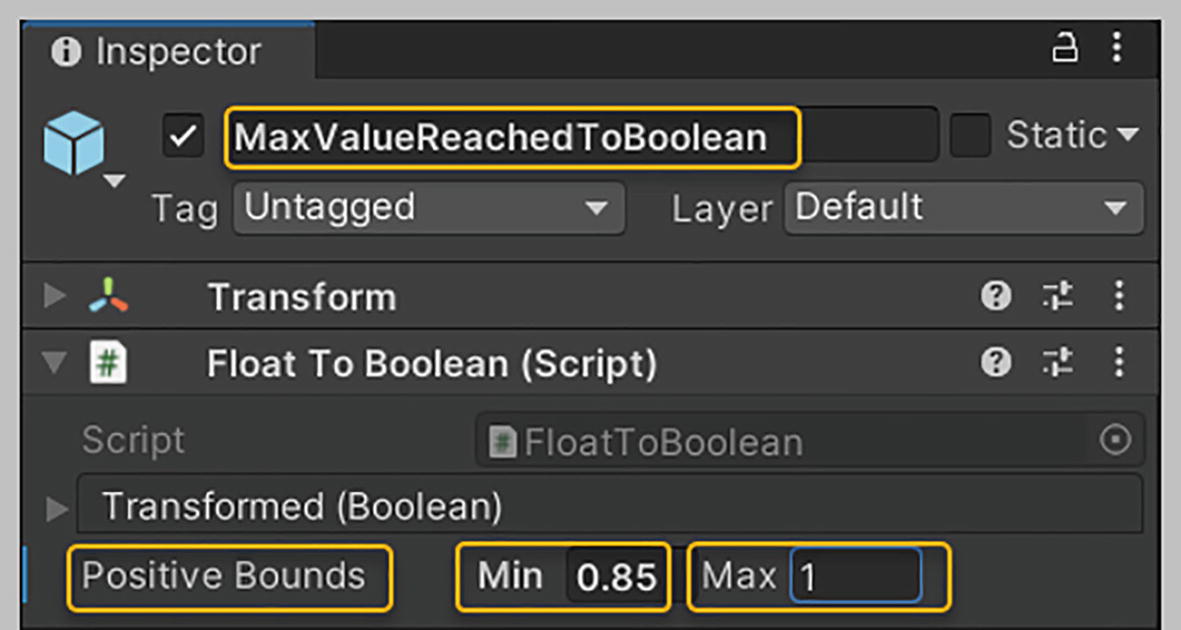
Tweaking the Min and Max values for the Positive Bounds property for the Max Value Reached To Boolean game object
Now, playtest the Demo scene using your VR headset, and watch as the Drive Limit values change in the Inspector. In the hierarchy, select the Interactions Angular Joint Drive, and in the Inspector, scroll down until you can see its Drive Limit property. Then, press the Play button in the Unity editor to playtest your scene. When your scene starts playing, you’ll see that your Drive Limit values start at Min = -45 and Max = 45. This indicates that you can now move your Lever either forward or backward.
Approach the Lever and grab it, then push it forward. Ensure that you push it all the way forward so that you see the change in the Drive Limit values in the Inspector. When you look at these values, you’ll see that they are now at Min = 0 and Max = 45. Now, grab the Lever again and attempt to pull it back. You’ll find that you can’t pull it back past its central position because your Drive Limit Min value is set to 0.
Now, exit playtest mode, so that you can validate that you’re able to pull the Lever back to its rearmost position. Press the Play button in the Unity editor to playtest the Demo scene again. When your scene loads, you’ll see that your Drive Limit values start as Min = -45 and Max = 45, which indicates that you can now move your Lever backward.
Approach the Lever and grab it, then pull it back far enough to see a change in the Drive Limit values in the Inspector. When you look at these values, you’ll see that they are now set at Min = -45 and Max = 0. Now, grab the Lever again and attempt to push it all the way forward. You’ll find that you can’t push it past its central position because your Drive Limit Max value is set to 0.
Now, let’s use the Midpoint Reached event. In it, when you reach the Midpoint, the Drive Limit’s Min value is set to -45 and its Max value to 45. This allows the Lever to rotate from its forward/drive position to its central/neutral position, from which it can rotate either to a backward/reverse position or to a forward/drive position. This is ideally how you would want the automatic transmission of your car to function—having the Lever move from neutral either forward or backward, and having it pause for a moment when it reaches neutral, rather than simply moving past its central/neutral position.
The only slight modification we will add here is to ensure that when our Lever is in its central/neutral position, it will halt there for a moment before its Drive Limit values are changed to Min = -45 and Max = 45. This results in providing you with a clean gear shift, from drive to neutral, followed by a short pause, and then allowing you to shift either forward or backward. Let’s implement this logic now.
Select the Lever Logic game object in the hierarchy, and create a new empty game object and rename it “Lever Mid Reached.” Select this empty game object in the hierarchy, and in the Inspector, add a new component called Empty Event Proxy Emitter. Expand its Emitted event, and click the plus symbol in its bottom right corner twice to add two event listeners. Now, drag and drop the Interactions Angular Joint Drive game object into both these event listener boxes.
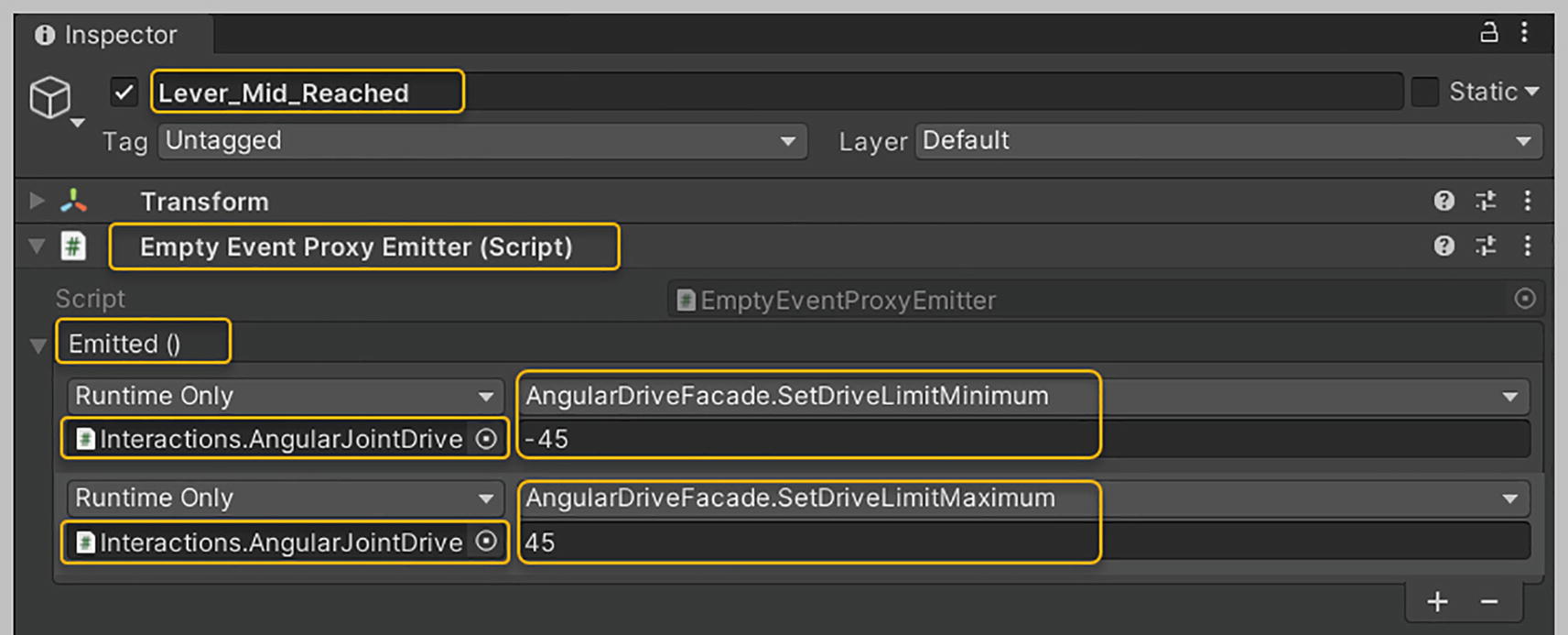
Setting up the Empty Event Proxy Emitter component on the Lever Mid Reached game object
Now, select the Lever logic game object in the hierarchy, and create another new empty game object and rename the empty game object “Neutral State.” With this game object selected, click the Add Component button in the Inspector and add the Wait For Seconds Realtime Yield Emitter component . Set its Seconds To Wait property value to 5. This may be a large value, but it’s suitable for testing purposes. You can always reduce the value once you test to ensure everything works well.

Setting up the Wait for Seconds Realtime Yield Emitter component on the Neutral State game object
Last, select the Midpoint Reached event game object in the hierarchy, and in the Inspector, expand the Activated (Boolean) event. Click the plus symbol located in the bottom right corner to add an event listener. Drag and drop the Neutral State game object into this event listener box. For the function, select Wait For Seconds, Realtime Yield Emitter, Begin() from the “Static Parameters” section, see Figure 19-27.
With this setup, whenever your Lever reaches its Midpoint, the Midpoint Reached event will be triggered. This, in turn, will invoke the logic you’ve built in the Neutral State. The Yielded event, within the Neutral State, is triggered after five seconds has elapsed since invoking the Neutral State. The Lever Mid Reached logic is then executed, setting the Drive Limit’s Min value to -45 and its Max value to 45.

Setting up the Midpoint Reached event to invoke the Neutral State logic object
Now, playtest the Demo scene, and you’ll see that you can move the Lever more realistically across the drive, neutral, and reverse modes. When in the central/neutral state, look at the Drive Limit values in the Inspector. You should find that your Drive Limit property has its Min set to -45 and its Max set to 45 if the Lever is centered and perfectly perpendicular. These values are set the moment the Midpoint Reached event is triggered. As stated earlier, you may need to further tweak the Min and Max values of the Positive Bounds property for the Min Value Reached To Boolean, Mid Value Reached To Boolean, and Max Value Reached To Boolean game objects to reach a sweet spot that works well for you. Getting these settings accurate is vital to ensuring that your events are triggered successfully.
In this section, we’ve delved deeper into dealing with some of the internal events provided by the VRTK. We also learned to build and link up simple game logic objects without writing any code.
Summary
This chapter has been all about using the Angular Drives provided by the VRTK. We learned to implement both an Angular Transform Drive and an Angular Joint Drive. We first set up a Steering Wheel that uses the VRTK’s Angular Transform Drive. You learned to set up various properties against this Angular Transform Drive and were introduced to the Drive Limit and Drive Axis properties. We went over how to set up a realistic Door that can be opened and closed. We used the Angular Joint Drive that uses Unity’s joints. You were introduced to the Hinge Location and Gizmo Line Distance properties. We reviewed setting up a Mutators Collision Ignorer prefab instead of using Unity’s Layer Collision Matrix. We became familiar with how to use the Start at Initial Target Value and Initial Target Value settings to have our Door start out in a shut state. We then went over the Step Range and Step Increment properties and saw how to sync them up with the Drive Limits’ permissible angle range. You learned to use the Started Moving event, which gets triggered when your Door begins to move. Finally, we playtested the Demo scene to ensure that the Door functions as desired. We then created a Lever that uses an Angular Joint Drive. We set up a Mutators Collision Ignorer here, too, and worked with the properties we used when creating our Door. You learned to use the Last Ungrabbed event to increase the Angular Drag against our Lever. We then explored the Angular Joint Drive value events and learned how to create logic game objects that did away with the necessity to write code. We learned to use the Minimum Reached, Midpoint Reached, and Maximum Reached event objects provided by the VRTK. We created four logic game objects that help track whether the Lever is in a drive, neutral, or reverse state. Along the way, we reviewed how to use two new VRTK-provided components: the Empty Event Proxy Emitter and the Wait for Seconds Realtime Yield Emitter. Finally, you learned to tweak the Positive Bounds’ Min and Max values for the Min Value Reached to Boolean, Mid Value Reached to Boolean, and Max Value Reached to Boolean objects to reach a sweet spot that works for our Lever.