
Chapter 6
The ATA/IDE Interface
The interface used to connect hard disk and optical drives to a modern PC is typically called IDE (Integrated Drive Electronics); however, the true name of this interface is ATA (AT Attachment). The ATA designation refers to the fact that this interface was originally designed to connect a combined drive and controller directly to the 16-bit bus found in the 1984 vintage IBM AT (Advanced Technology) and compatible computers. The AT bus is otherwise known as the ISA (Industry Standard Architecture) bus. Although ATA is the official name of the interface, IDE is a marketing term originated by some of the drive manufacturers to describe the drive/controller combination used in drives with the ATA interface. IDE refers to the fact that the interface electronics or controller is built in to the drive and is not a separate board, as with earlier drive interfaces. Although the correct name for the particular IDE interface we most commonly use is technically ATA, many persist in using the IDE designation today. If you are being picky, you could say that IDE refers generically to any drive interface in which the controller is built in to the drive, whereas ATA refers to the specific implementation of IDE that is used in most PCs.
ATA is used to connect not only hard disks, but also optical (CD-ROM and DVD-ROM) drives, high-capacity SuperDisk or Zip drives, and tape drives. Even so, ATA is still thought of primarily as a hard disk interface, and it evolved directly from the separate controller and hard drive interfaces that were used prior to ATA. This chapter covers the standard parallel version of ATA as well as the newer Serial ATA (SATA) interfaces; it also briefly mentions the original interfaces from which ATA evolved.
Although virtually every server contains one or more ATA interfaces, the parallel ATA (PATA) interface is used primarily for CD-ROM and DVD-ROM optical drives on midrange and high-end servers. These servers typically use the SCSI interface for hard disks. However, the newer SATA interface is being used by all levels of servers for hard disk interfacing.
Origins of IDE
Any drive with an integrated controller could be called an IDE drive, although normally when we say IDE, we really mean the specific version of IDE called ATA. No matter what you call it, combining the drive and controller greatly simplifies installation because there are no separate power or signal cables that run from the controller to the drive. Also, when the controller and drive are assembled as a unit, the number of total components is reduced, signal paths are shorter, and the electrical connections are more noise resistant. This results in a more reliable and less expensive design than is possible when a separate controller, connected to the drive by cables, is used, as was the case with the early ST412, ST506, and ESDI interfaces used by PCs and early servers in the 1980s.
Placing the controller, including the digital-to-analog encoder/decoder (endec), on the drive offers an inherent reliability advantage over interfaces with separate controllers, such as the ST506 and ESDI. Reliability is increased because the digital-to-analog data encoding is performed directly on the drive in a tight, noise-free environment. The timing-sensitive analog information does not have to travel along crude ribbon cables that are likely to pick up noise and insert propagation delays into the signals. The integrated configuration enables increases in the clock rate of the encoder and the storage density of the drive.
Integrating the controller and drive also frees the controller and drive engineers from having to adhere to the strict guidelines imposed by the earlier interface standards. Engineers can design what essentially are custom drive and controller implementations because no other controller will ever have to be connected to the drive. The resulting drive and controller combinations can offer higher performance than earlier standalone controller and drive setups. IDE drives are sometimes called drives with embedded controllers.
The earliest IDE drives were called hardcards and were nothing more than hard disks and controllers bolted directly together and plugged in to a slot as a single unit. Companies such as the Plus Development Division of Quantum attached a small 3.5-inch drive (either ST-506/412 or ESDI) directly to a standard controller. The drive/controller assembly was then plugged in to an ISA bus slot as though it were a normal disk controller card. To improve reliability and free up the expansion slot blocked by the relatively thick card-and-drive combination, several companies got the idea to redesign the controller, to replace the logic board assembly on a standard hard disk and then mount it in a standard drive bay just like any other drive. Because the built-in controller in these drives still needed to plug directly in to the expansion bus, just like any other controller, a cable was run between the drive and one of the slots. This is the origin of IDE.
IDE Variations
There have been four main types of IDE interfaces, based on three bus standards:
- SATA
- PATA (based on the 16-bit AT-bus, also called ISA)
- XT IDE (based on 8-bit ISA, obsolete)
- MCA IDE (based on 16-bit Micro Channel, obsolete)
Of these, only the PATA and SATA versions are used today. PATA and SATA have evolved with newer, faster, and more powerful versions. The newer versions of PATA are referred to as ATA-2 and higher. They are also sometimes called EIDE (Enhanced IDE), Fast ATA, Ultra ATA, or Ultra DMA (UDMA). Even though PATA has hit the end of the evolutionary road with ATA-7, SATA picks up where PATA leaves off and offers greater performance, higher reliability, easier installation, lower cost, and an established roadmap for future upgrades.
Note
It is important to note that only the ATA IDE interface has been standardized by the industry. The XT and MCA IDE interfaces were never adopted as industrywide standards and never became very popular. These interfaces were only used from 1987 to 1993 and only in IBM PS/2 (and some early ThinkPad) systems.
In most modern server systems, you find one or more PATA connectors on the motherboard, and systems that offer ATA RAID have two additional PATA connectors, which can be used for an ATA RAID array or for additional ATA drives running as independent devices. If your motherboard does not have one of these connectors and you want to attach an ATA drive to your system, you can purchase an adapter card that adds an ATA interface (or two) to a system via the PCI or PCI-X bus slots. Some of the cards offer additional features, such as an onboard ROM BIOS or cache memory.
Because only the PATA and SATA versions of IDE are in use today, this chapter focuses on them.
Note
Many people who use systems with ATA connectors on the motherboard believe that a hard disk controller is built in to their motherboard, but in a technical sense, the controller is actually in the drive. Although the integrated ATA ports on a motherboard are often referred to as controllers, they are more accurately called host adapters (although you rarely hear this term). A host adapter can be thought of as a device that connects a controller to a bus.
PATA is a 16-bit parallel interface, meaning that 16 bits are transmitted simultaneously down the interface cable. A serial interface called SATA was officially introduced in late 2000 and began appearing in systems starting in 2003. SATA sends 1 bit down the cable at a time, enabling thinner and smaller cables to be used and providing higher performance due to the higher cycling speeds allowed. SATA is a completely new and updated physical interface design, while remaining compatible on the software level with PATA. (Throughout this book, ATA refers to both the parallel and serial versions, whereas PATA and SATA refer to the specific versions, as indicated.) Figure 6.1 shows how the power and data cables used by SATA compare in size to those used by PATA.
Figure 6.1 SATA data cables (lower right) are much smaller than those used by PATA (upper right), whereas the power cables (left) are similar in size.

The primary advantage of ATA drives over the older, separate controller-based interfaces and newer host bus interface alternatives, such as USB, SCSI, and IEEE 1394 (i.LINK or FireWire), is cost. Because the separate controller or host adapter is eliminated and the cable connections are simplified, ATA drives cost much less than a standard controller-and-drive combination.
![]() See "ANSI SCSI Standards," p. 449.
See "ANSI SCSI Standards," p. 449.
In terms of performance, ATA drives are often some of the highest-performance drives available, but they can also be among the lowest-performance drives. This apparent contradiction is a result of the fact that all ATA drives are different. You can't make a blanket statement about the performance of ATA drives because each drive is unique. The high-end models, however, offer performance equal to or superior to that of any other type of drive on the market for a single-user, single-tasking operating system. However, because of the simplicity of the ATA design, PATA in particular is not suitable for midrange or high-end server designs. PATA is adequate for entry server designs, though.
Note
Many people are confused about 16- versus 32-bit bus connections and 16- versus 32-bit hard drive connections. A PCI bus connection allows for a 32-bit (and possibly 64-bit, in some versions) connection between the bus and the ATA host interface, which is typically in the motherboard chipset South Bridge or I/O Controller Hub (ICH) chip. However, the actual PATA interface between the host connector on the motherboard and the drive (or drives) itself is only a 16-bit interface. Thus, in a PATA drive configuration, you are still getting only 16-bit transfers between the drive and the motherboard-based host interface. Even so, the clock speeds of the ATA interface are high enough that one or two hard drives normally can't supply the controller enough data to saturate even a 16-bit channel. The same is true with SATA, which—although it transmits only 1 bit at a time—does so at extremely high speeds.
ATA Standards
Today, the ATA interface is controlled by an independent group of representatives from major PC, drive, and component manufacturers. This group, called Technical Committee T13 (www.t13.org), is responsible for all standards related to the PATA and SATA storage interfaces. Technical Committee T13 is a part of the InterNational Committee on Information Technology Standards (INCITS; www.incits.org), which operates under rules approved by the American National Standards Institute (ANSI; www.ansi.org), a governing body that sets rules that control nonproprietary standards in the computer industry as well as many other industries. A second group, called the Serial ATA Working Group (now the Serial ATA International Organization [SATA-IO; www.serialata.org]) was formed to initially create the SATA standards, which are then passed on to Technical Committee T13 for refinement and official publication under ANSI. The current ATA-7 standard incorporates both PATA and SATA standards and represents the end of the road for PATA because ATA-8 and beyond will contain only SATA standards.
The rules under which these committees operate are designed to ensure that voluntary industry standards are developed through the consensus of people and organizations in the affected industries. INCITS specifically develops information processing system standards; ANSI approves the process under which they are developed and then publishes them. Because Technical Committee T13 is essentially a public organization, all the working drafts, discussions, and meetings of Technical Committee T13 are open for all to see.
Copies of any of the published standards can be purchased from ANSI or Global Engineering Documents (see the vendor list in Appendix C, "Vendor List"). Draft versions of the standards can be downloaded from Technical Committee T13 and SATA-IO websites.
The ATA interface has evolved into several successive standard versions:
- ATA-1
- ATA-2 (also called Fast ATA, Fast ATA-2, and EIDE)
- ATA-3
- ATA-4 (Ultra ATA/33)
- ATA-5 (Ultra ATA/66)
- ATA-6 (Ultra ATA/100)
- ATA-7 (Ultra ATA/133 or SATA)
- SATA-8 (SATA II)
Since ATA-1, newer versions of the ATA interface and complementary BIOS have supported larger and faster drives, as well as different types of devices other than hard disks. ATA-2 and later have improved the original ATA interface in five main areas:
- Secondary two-device channel
- Increased maximum drive capacity
- Faster data transfer
- ATAPI (AT Attachment Packet Interface)
- SATA (Serial ATA)
Each newer version of ATA is backward compatible with the previous versions. In other words, older ATA-1 or ATA-2 devices work fine on ATA-6 and ATA-7 interfaces. ATA-7 includes both PATA and SATA, but SATA-8 is serial only. Newer versions of ATA are normally built on older versions and with few exceptions can be thought of as extensions of the previous versions. This means that ATA-7, for example, is generally considered equal to ATA-6, with the addition of some features.
Table 6.1 breaks down the various ATA standards. The following sections describe all the ATA versions in more detail.
Table 6.1 ATA Standards1

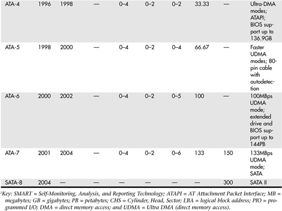
Virtually all recent servers support ATA-6 or newer ATA standards, so the following sections discuss these standards in greater detail.
ATA-6/ATAPI
The ATA-6 standard includes Ultra ATA/100 (also called UDMA/100), which increases the Ultra ATA burst transfer rate by reducing setup times and increasing the clock rate. As with ATA-5, the faster modes require the improved 80-conductor cable (refer to Figure 6.6, later in this chapter, for a comparison of the original 40-conductor and current 80-conductor PATA cables). Using the ATA/100 mode requires both a drive and a motherboard interface that supports that mode.
Work on ATA-6 began in 2000, and the standard was finished and officially published in 2002, as ANSI NCITS 361-2002, "AT Attachment - 6 with Packet Interface."
The major changes or additions in the standard include the following:
- UDMA Mode 5 was added, which allows 100MBps (called UDMA/100, Ultra ATA/100, or just ATA/100) transfers. This requires an 80-conductor cable.
- The sector count per command was increased from 8 bits (256 sectors, or 131KB) to 16 bits (65,536 sectors, or 33.5MB), allowing larger files to be transferred more efficiently.
- LBA addressing was extended from 228 to 248 (281,474,976,710,656) sectors, supporting drives up to 144.12PB (petabytes = quadrillion bytes). Vendors often refer to this feature as 48-bit LBA, or greater than 137GB support; Maxtor refers to this feature as Big Drive.
- CHS addressing was made obsolete; drives must use 28-bit or 48-bit LBA addressing only.
Besides adding the 100MBps UDMA Mode 5 transfer rate, ATA-6 also extended drive capacity greatly—and just in time. ATA-5 and earlier standards supported drives of up to only 137GB in capacity, which became a limitation because larger drives were becoming available. Commercially available 3.5-inch drives exceeding 137GB were introduced during 2001, but they were originally available only in SCSI versions because SCSI doesn't share the same limitations as ATA. With ATA-6, the sector addressing limit was extended from 228 sectors to 248 sectors. This means that LBA addressing previously could use only 28-bit numbers, but with ATA-6, LBA addressing can use larger 48-bit numbers, if necessary. With 512 bytes per sector, this raises the maximum supported drive capacity to 144.12PB, which is equal to more than 144.12 quadrillion bytes. Note that the 48-bit addressing is optional and necessary only for drives larger than 137GB. Drives 137GB or smaller can use either 28-bit or 48-bit addressing.
ATA-7/ATAPI
The primary addition in ATA-7 is another transfer mode for PATA, called UDMA Mode 6, that allows for data transfers up to 133MBps. As with UDMA Mode 5 (100MBps) and UDMA Mode 4 (66MBps), the use of an 80-conductor cable is required. Slower speeds don't require the 80-conductor cable, although they do work with it and an 80-conductor cable is always preferred over the 40-conductor type.
Another major change in the specification is the inclusion of the SATA 1.0 specification into ATA-7. This makes SATA an official part of the ATA standard. Work on ATA-7 began in 2001, and the standard was finished and officially published in 2004.
Note that although the throughput has been increased from the drive controller (on the drive) to the motherboard via the UDMA modes, most ATA drives—even those capable of UDMA Mode 6 (133MBps) from the drive to the motherboard—still have an average maximum sustained transfer rate while reading data of under 60MBps. This means that although newer ATA drives can transfer at speeds up to 133MBps from the circuit board on the drive to the motherboard, data from the drive media (platters) through the heads to the circuit board on the drive moves at less than half that rate. For that reason, running a drive capable of UDMA Mode 6 (133MBps) on a motherboard capable of only UDMA Mode 5 (100MBps) really doesn't slow things down much, if at all. Likewise, upgrading your ATA host adapter from one that does 100MBps to one that can do 133MBps doesn't help much if your drive reads data off the disk platters at only half that speed. When selecting a drive, remember that the media transfer rate is far more important than the interface transfer rate because the media transfer rate is the limiting factor.
ATA-8
In 2004, work began on SATA-8, which is a new ATA standard based on ATA-7. The following are the main features of SATA-8:
- The development of separate SATA and PATA versions of the standard
- The replacement of read-long/write-long functions
- Improved host protected area (HPA) management
The most dramatic change is the development of separate PATA and SATA standards. ATA8 for PATA drives is known as ATA8-APT (ATA/ATAPI Parallel Transport), while ATA8 for SATA drives is known as ATA8-AST (ATA/ATAPI Serial Transport). The main benefit of this change is to allow new features and functions to be made available in ATA8-SPT–compliant SATA drives while providing a PATA-specific standard that can be used as a reference. By creating separate standards for PATA and SATA, the result is a clearer and more concise description of the SATA standard. ATA8-APT is virtually identical to the PATA-specific content of ATA-7. Basically, any PATA drive compliant with ATA-7 is also compliant with ATA8-APT. It is expected that both versions of the ATA8 standard will be finalized and officially published in 2006.
ATA Features and Resource Allocations
Although ATA drives are now following two divergent paths in terms of hardware (PATA and SATA), they have the ATA-7 command set in common. The following sections discuss the different ATA standards and the ATA command set.
PATA
PATA and SATA have unique specifications and requirements regarding the physical interface, cable, and connectors. The following sections detail the unique features of PATA.
PATA I/O Connector
The PATA interface connector is normally a 40-pin header-type connector with pins spaced 0.1 inch (2.54mm) apart, and it is generally keyed, to prevent the possibility of installing it upside down (see Figures 6.2 and 6.3). There are two methods of creating a keyed connector:
- Pin 20 might be removed from the male connector and the matching pin 20 on the female cable connector is blocked, which prevents the user from installing the cable backward.
- Some cables incorporate a protrusion on the top of the female cable connector that fits into a notch in the shroud surrounding the mating male connector on the device.
Figure 6.2 Typical PATA (IDE) hard drive connectors.
Some cables use both keying methods. The use of keyed connectors and cables is highly recommended. Plugging in an ATA cable backward normally doesn't cause any permanent damage; however, it can lock up a system and prevent it from running.
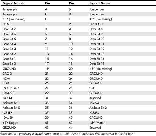
Table 6.2 shows the standard 40-pin PATA (IDE) interface connector pinout. Note that although PATA drives corresponding to the ATA-5 and later standards use an 80-conductor (80-wire) cable, the connector and pinout remain the same as those shown in Figures 6.2 and 6.3.
Table 6.2 40-Pin PATA Connector
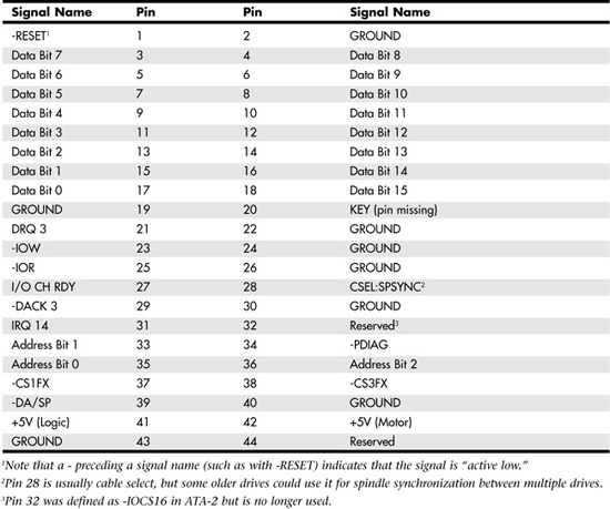
Figure 6.3 PATA (IDE) 40-pin interface connector detail.
The 2.5-inch drives found in notebook/laptop-size computers and in server blades typically use a smaller, unitized 50-pin header connector with pins spaced only 2.0mm apart. The main 40-pin part of the connector is the same as the standard PATA connector (except for the physical pin spacing), but there are added pins for power and jumpering. The cable that plugs in to this connector typically has 44 pins, carrying power as well as the standard ATA signals. The jumper pins usually have a jumper on them (the jumper position controls cable select, master, or slave settings). Figure 6.4 shows the unitized 50-pin connector used on the 2.5-inch PATA drives in laptop and notebook computers and in server blades.
Figure 6.4 50-pin unitized PATA connector detail (used on 2.5-inch notebook/laptop/server blade PATA drives with a 44-pin cable).

Note the jumper pins at positions A–D and that the pins at positions E and F are removed. A jumper is usually placed between positions B and D to set the drive for cable select operation. On this connector, pin 41 provides +5V power to the drive logic (circuit board), pin 42 provides +5V power to the motor (2.5-inch drives use 5V motors, unlike larger drives that typically use 12V motors), and pin 43 provides a power ground. The last pin (44) is reserved and not used.
Table 6.3 shows the 50-pin unitized PATA interface connector pinout, which is used on most 2.5-inch (laptop or notebook computer/server blade) drives.
Table 6.3 50-Pin Unitized PATA 2.5-Inch (Notebook/Laptop/Server Blade Drive) Connector Pinout
PATA I/O Cables
A 40-conductor ribbon cable is specified to carry signals between the bus adapter circuits and the drive (controller). To maximize signal integrity and eliminate potential timing and noise problems, the cable should not be longer than 18-inches, although testing shows that 80-conductor cables up to 27 inches in length can be used reliably.
Note that ATA drives supporting the higher-speed transfer modes, such as programmed I/O (PIO) Mode 4 or any of the UDMA modes, are especially susceptible to cable integrity problems and cables that are too long. If the cable is too long, you can experience data corruption and other maddening errors. This is manifested in problems reading from or writing to the drive. In addition, any drive that uses UDMA Mode 5 (66MBps transfer rate), Mode 6 (100MBps transfer rate), or Mode 7 (133MBps transfer rate) must use a special, higher-quality 80-conductor cable; the extra conductors are grounds to reduce noise. You should also use this type of cable if your drive is running at UDMA Mode 2 (33MBps) or slower because it can't hurt and can only help. It's a good idea to keep a high-quality 80-conductor ATA cable in your toolbox for testing drives where you suspect cable integrity or cable length problems. Figure 6.5 shows the typical ATA cable layout and dimensions.
Figure 6.5 PATA (IDE) cable, with 40-pin connectors and either 40- or 80-conductor cables. (Additional wires are grounded in 80-conductor versions.)
Note
Most 40-conductor cables do not color-code the connectors, whereas virtually all 80-conductor cables do color-code the connectors.
Two primary variations of PATA cables are used today: one with 40 conductors and one with 80 conductors (see Figure 6.6). Both use 40-pin connectors, and the additional wires in the 80-conductor version are simply wired to ground. The additional conductors are designed to reduce noise and interference and are required when setting the interface to run at 66MBps (ATA/66) or faster. The drive and host adapter are designed to disable the higher-speed ATA/66, ATA/100, or ATA/133 modes if an 80-conductor cable is not detected. In such cases, you might see a warning message when you start your computer if an ATA/66 or faster drive is connected to a 40-conductor cable. The 80-conductor cable can also be used at lower speeds; although this is unnecessary, it improves the signal integrity. Therefore, it is the recommended version, no matter which drive you use.
Figure 6.6 40-conductor (left) and 80-conductor (right) PATA cables.
Note
How do you tell an 80-conductor cable from a 40-conductor cable? Each conductor in a ribbon cable can be seen as a rib or ridge in the cable. You need to count the ridges (conductors) in the cable. If you count only 40, it must be a 40-conductor cable, and if you count to 80, well...you get the idea. If you observe the two cables side-by-side, the difference is clear: The 80-conductor cable has an obviously smoother, less ridged appearance than the 40-conductor cable.
Note in Figure 6.6 that the keying on the 80-conductor cable is designed to prevent backward installation. Note also that the poorly constructed 40-conductor cable shown in this example lacks keying. Most good 40-conductor cables include the keying; however, because it is optional, many cheaply constructed versions do not include it. Keying was made mandatory for all 80-conductor cables as part of the standard.
Longer Cables and Rounded Cables
The official PATA standard limits cable length to 18 inches; however, many of these cables that are sold are longer, up to even 36 inches or more in length. Why would people sell cables longer than 18 inches if the standard doesn't allow it? Well, just because something is for sale doesn't mean it conforms to the standards and will work properly.
Improperly designed, poorly manufactured, and nonconforming items are for sale all the time. Still, many people have used the longer cables, and their systems seem to work fine, but there have also been numerous cases in which using longer cables has caused problems.
It turns out that you can use longer 80-conductor cables reliably up to 27 inches in length, but 40-conductor cables should remain limited to 18 inches, just as the standard indicates. In fact, an attempt was made to change the PATA standard to allow 27-inch cables. Read www.t13.org/technical/e00151r0.pdf, and you'll see data from a proposal that shows "negligible differences in Ultra DMA Mode 5 signal integrity between a 27-inch, 80-conductor cable and an 18-inch, 80-conductor cable." This extended cable design was actually proposed in October 2000, but it was never incorporated into the standard. Even though it was never officially approved, the information presented in this proposal is empirical evidence for allowing the use of 80-conductor cables up to 27 inches in length.
Regardless of their length, in general you should not use "rounded" ATA cables. A rounded design is popular with case modders working on high-performance desktop PCs, but it has not been approved in the ATA standard, and there is some evidence that these cables can cause problems with cross-talk and noise. The design of 80-conductor cables is such that a ground wire is interspersed between each data wire in the ribbon, and rounding the cable causes some of the data lines to run parallel or adjacent to each other at random, thereby causing cross-talk and noise and resulting in signal errors. Signal errors are unacceptable in a mission-critical environment such as a server.
There is an interview with Rahul Sood, the chief technology officer of Voodoo PC (www.voodoopc.com), a popular system builder, in the March 2004 issue of CPU (www.computerpoweruser.com). In the CPU interview, Sood said, "I don't agree with rounded cables, I never have. SATA cables are great, of course, but rounded [PATA] cables are a different story because there is potential for noise. Any benchmarks that I've run on any of the rounded cables that we've tested show either errors generating over time or they're slower than good quality flat IDE cables."
Of course, many people are using rounded cables with success, but electrical engineers and the ATA standard don't encourage their use. It is best to stick with 80-conductor ribbon cables of 27 inches or less in length.
Tip
If you are concerned about the airflow problems that can result from flat cables, you can try these two solutions:
- Carefully fold (but do not crease!) ATA cables to reduce excess length after you install them and secure the folded section with a nylon cable tie.
- Replace PATA drives with SATA drives, which use a very small rounded cable natively.
PATA Signals
This section describes in more detail some of the most important PATA signals having to do with drive configuration and installation. Understanding these signals is important in understanding how the drive operates and, in turn, understanding how the cable select feature works, for example.
As mentioned earlier in this chapter, pin 20 is used as a key pin for cable orientation, and it is not connected to the interface. This pin should be missing from any ATA connectors, and the cable should have the pin 20 hole in the connector plugged off to prevent the cable from being plugged in backward.
Pin 39 carries the drive active/slave present (DASP) signal, which is a dual-purpose, time-multiplexed signal. During power-on initialization, this signal indicates whether a slave drive is present on the interface. After that, each drive asserts the signal to indicate that it is active. Early drives could not multiplex these functions and required special jumper settings to work with other drives. Standardizing this function to allow for compatible dual-drive installations is one of the features of the ATA standard. This is why some drives require a slave present (SP) jumper, whereas others do not.
Pin 28 carries the cable select (CSEL) signal. In some older drives, it could also carry a spindle synchronization (SPSYNC) signal, but that is not commonly found on newer drives. The CSEL function is the most widely used and is designed to control the designation of a drive as master (drive 0) or slave (drive 1), without requiring jumper settings on the drives. If a drive sees the CSEL as being grounded, the drive is a master; if CSEL is open, the drive is a slave.
Standard 80-wire cables support CSEL. The connector at the far end of the cable from the host adapter connection has the CSEL line connected through, indicating a master drive; the connector at the middle of the cable has the CSEL line open (showing that the conductor is interrupted or removed), making the drive at that end the slave.
PATA Dual-Drive Configurations
Dual-drive PATA installations can be problematic because each drive has its own controller, and both controllers must function while being connected to the same bus. There has to be a way to ensure that only one of the two controllers will respond to a command at a time.
The ATA standard provides the option of operating on the AT bus with two drives in a daisy-chained configuration. The primary drive (drive 0) is called the master, and the secondary drive (drive 1) is called the slave. You designate a drive as being master or slave by setting a jumper or switch on the drive or by using a special line in the interface called the cable select (CS or CSEL) pin and setting the CS/CSEL jumper on the drive.
When only one drive is installed, the controller responds to all commands from the system. When two drives (and, therefore, two controllers) are installed, both controllers receive all commands from the system. Each controller must then be set up to respond only to commands for itself. In this situation, one controller must be designated as the master and the other as the slave. When the system sends a command for a specific drive, the controller on the other drive must remain silent while the selected controller and drive are functioning. When you set the jumper to master or slave, you can also enable discrimination between the two controllers by setting a special bit (the DRV bit) in the drive/head register of a command block.
Configuring ATA drives can be simple, which is the case with most single-drive installations. Or it can be troublesome, especially when it comes to mixing two (primarily older) drives from different manufacturers on a single cable.
Most ATA drives can be configured with four possible settings:
- Master, single-drive
- Master, dual-drive
- Slave, dual-drive
- Cable select
Many drives simplify this to three settings: master, slave, and cable select. Because each ATA drive has its own controller, you must specifically tell one drive to be the master and the other to be the slave. No functional difference exists between the two, except that the drive that's specified as the slave will assert a DASP signal after a system reset informs the master that a slave drive is present in the system. The master drive then pays attention to the drive select line, which it otherwise ignores. Telling a drive that it's the slave also usually causes it to delay its spin-up for several seconds to allow the master to get going and thus to lessen the load on the system's power supply.
Until the ATA specification, no common implementation for drive configuration was in use. Some drive companies even used different master/slave methods for different models of drives. Because of these incompatibilities, some drives work together only in a specific master/slave or slave/master order. This situation mostly affects older IDE drives introduced before the ATA specification, but it has been known to take place with certain combinations of newer ATA drives.
Most drives that fully follow the ATA specification now need only one jumper (master/slave) for configuration. A few also need a slave present jumper, as well. Table 6.4 shows the jumper settings required by most ATA drives.
Table 6.4 Jumper Settings for Most ATA-Compatible Drives on Standard (Non–Cable Select) Cables

Note
If a CS cable is used, the CS jumper should be set to On, and all others should be set to Off. The cable connector then determines which drive will be master or slave.
Figure 6.7 shows the jumpers on a typical ATA drive.
Figure 6.7 PATA (IDE) drive jumpers for most drives.

The master jumper indicates that the drive is a master or a slave. Some drives also require a slave present jumper, which is used only in a dual-drive setup and is installed only on the master drive—which is somewhat confusing. This jumper tells the master that a slave drive is attached. With many PATA drives, the master jumper is optional and can be left off. Installing this jumper doesn't hurt in these cases and can eliminate confusion; you should install the jumpers listed here. Note that most Western Digital drives have a fourth jumper option: single drive. This is actually a "no-jumper" configuration in which the jumper is removed or parked across two pins horizontally so no circuit is completed. Western Digital drives that specify removing the jumper in a single-drive configuration do not work properly if the master jumper is applied. However, in a dual-drive configuration, the jumpers on Western Digital drives work as listed in Table 6.4.
Note
Some drives have these jumpers on the drive circuit board on the bottom of the drive, and they therefore might not be visible on the rear. Some vendors provide a jumper guide on the top of the drive, while others require you to look up the jumpering in drive documentation.
To eliminate confusion over master/slave settings, most newer systems now use the cable select option. Cable select requires an 80-wire UDMA cable (these cables have all the wires except pin 28 running from the motherboard connector to both drive connectors. Pin 28 is used for cable select and is connected to one of the drive connectors (labeled master) and not to the other (labeled slave). Both drives are then configured in cable select mode via the CS jumper on each drive.
With cable select, the drive that receives signals on pin 28 automatically becomes the master, and the other becomes the slave. Most cables implement this by removing the metal insulation displacement bit from the pin-28 hole, which can be difficult to see at a glance. Other cables have a section of pin 28 visibly cut from the cable somewhere along the ribbon. Because this is such a minor modification to the cable and can be difficult to see, cable select cables typically have the connectors labeled master, slave, and system, indicating that the cable controls these options rather than the drive. All 80-conductor Ultra ATA cables are designed to use cable select.
With cable select, you simply set the CS jumper on all drives and then plug the drive you want to be the master in to the connector labeled master on the cable, and you plug the drive you want to be the slave in to the connector labeled slave.
The only downside to using cable select is that it can restrict how the cable is routed or where you mount the drive that is to be master versus slave because they must be plugged in to specific cable connector positions.
Caution
Although it's possible to connect two PATA or ATAPI drives to the same PATA host adapter, you should not connect a tape backup drive or optical drive to the same host adapter as the hard disk. PATA isn't as intelligent an interface as SCSI, and connecting drives that will be used at the same time to the same host adapter limits read and write throughput. However, it's okay to connect drives that will not be used at the same time, such as a tape backup and an optical drive, to the same PATA host adapter.
PATA PIO Transfer Modes
ATA-2 and ATA-3 defined the first of several higher-performance PIO modes for transferring data over the PATA interface, to and from the drive. These faster modes were the main part of the newer specifications and were the main reason they were initially developed.
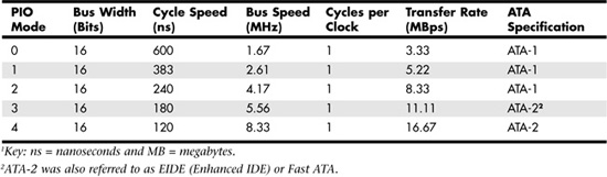
The PIO mode determines how fast data is transferred to and from the drive, using PIO transfers. In the slowest possible mode—PIO Mode 0—the data cycle time can't exceed 600ns (nanoseconds). In a single cycle, 16 bits are transferred into or out of the drive, making the theoretical transfer rate of PIO Mode 0 (600ns cycle time) 3.3MBps, whereas PIO Mode 4 (120ns cycle time) achieves a 16.6MBps transfer rate.
Table 6.5 shows the PIO modes, with their respective transfer rates.
Table 6.5 PIO Modes and Transfer Rates1
Most motherboards with ATA-2 or greater support incorporate dual ATA connectors. Most of the motherboard chipsets include the ATA interface in their South Bridge components, which in most systems is tied to the PCI bus.
When interrogated with an Identify Drive command, a hard disk returns, among other things, information about the PIO and DMA modes it is capable of using. Most enhanced BIOSs automatically set the correct mode to match the capabilities of the drive. If you set a mode faster than the drive can handle, data corruption results.
ATA-2 and newer drives also perform Block Mode PIO, which means they use the Read Multiple and Write Multiple commands, which greatly reduce the number of interrupts sent to the host processor. This lowers the overhead, and the resulting transfers are even faster.
PATA DMA Transfer Modes
ATA drives also support direct memory access (DMA) transfers. Unlike with PIO, DMA transfers, are performed directly between drive and memory, without using the CPU as an intermediary. This has the effect of offloading much of the work of transferring data from the processor, in effect allowing the processor to do other things while the transfer is taking place.
There are two distinct types of DMA: single-word (8-bit) and multiword (16-bit) DMA. Single-word DMA modes were removed from the ATA-3 and later specifications and are obsolete. DMA modes are also sometimes called busmaster ATA modes because they use a host adapter that supports busmastering. Ordinary DMA relies on the legacy DMA controller on the motherboard to perform the complex task of arbitration, grabbing the system bus and transferring the data. In the case of busmastering DMA, all this is done by a higher-speed logic chip in the host adapter interface (which is also on the motherboard).
Systems that use the Intel PIIX (PCI IDE ISA eXcelerator) and later South Bridge chips (or third-party equivalents) have the capability of supporting busmaster ATA. The single-word and double-word busmaster ATA modes and transfer rates are shown in Tables 6.6 and 6.7.
Table 6.6 Single-Word (8-bit) DMA Modes and Transfer Rates

Table 6.7 Multiword (16-bit) DMA Modes and Transfer Rates

Note that double-word DMA modes are also called busmaster DMA modes by some manufacturers. Unfortunately, even the fastest double-word DMA Mode 2 results in the same 16.67MBps transfer speed as PIO Mode 4. However, even though the transfer speed is the same as that of PIO, because DMA offloads much of the work from the processor, overall system performance is higher. Even so, multiword DMA modes were never very popular and have been superseded by the newer UDMA modes supported in devices that are compatible with ATA-4 through ATA-7.
Table 6.8 shows the UDMA modes now supported in the ATA-4 through ATA-7 specifications. Note that in order to use this feature, you need to install the correct drivers for your host adapter and version of Windows.
Table 6.8 UDMA Support in ATA-4 Through ATA-71
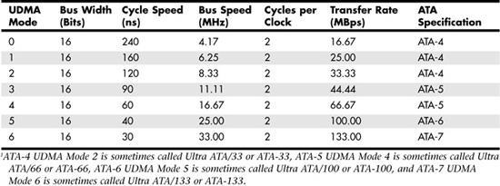
Note that hardly any systems ever supported the 44.44Mbps UDMA Mode 3 transfer rate and that UDMA Mode 4 and higher transfer rates require 80-conductor cables.
Some of the older UMDA Mode 4 and UDMA Mode 5 drives require you to run a special utility to configure the drive to run at UDMA Mode 4 or faster speeds. For details, see the documentation for your hard disk drive.
SATA
Although ATA8-APT is a forthcoming PATA drive standard, it contains no improvements in performance over ATA-7. Sending data at rates faster than 133MBps down a parallel ribbon cable is fraught with all kinds of problems because of signal timing, electromagnetic interference (EMI), and other integrity problems. The solution is SATA, which is an evolutionary replacement for the venerable PATA physical storage interface. SATA is software-compatible with PATA, which means it fully emulates all the commands, registers, and controls so that existing software can run on the new architecture without any changes. In other words, the existing BIOSs, operating systems, and utilities that work on PATA also work on SATA.
Of course, PATA and SATA do differ physically—that is, you can't plug PATA drives in to SATA host adapters and vice versa unless you use a signal converter. The physical changes are all for the better because SATA uses much smaller and thinner cables, with only seven conductors, that are easier to route inside the PC and easier to plug in, with smaller, redesigned cable connectors. The interface chip designs are also improved, with far fewer pins and lower voltages. These improvements are all designed to eliminate the design problems inherent in PATA.
Figure 6.8 shows the official SATA-IO logo used to identify most SATA devices.
Figure 6.8 The SATA-IO official logo, which is used to identify SATA devices.

Although SATA won't immediately replace PATA, most new servers and server motherboards include SATA interfaces alongside PATA interfaces. In many cases, the traditional duo of PATA host adapters is reduced to one, while two or more SATA host adapters are used. Eventually, SATA will replace PATA as the de facto standard internal storage device interface found in servers. As current motherboard designs indicate, the transition from ATA to SATA is a gradual one, and during this transition, PATA capabilities will continue to be available. With more than a 10-year history, PATA devices will likely continue to be available even after most servers have switched to SATA. Because of the higher native performance and greater growth potential of SATA, some servers now feature SATA interfaces in place of SCSI interfaces.
Development for SATA started when the SATA Working Group effort was announced at the Intel Developer Forum in February 2000. The initial members of the SATA Working Group included APT Technologies, Dell, IBM, Intel, Maxtor, Quantum, and Seagate. The first SATA 1.0 draft specification was released in November 2000 and was officially published as a final specification in August 2001. The SATA II extensions to this specification, which make SATA suitable for network storage, were released in October 2002.
The SATA Working Group was incorporated in July 2004 into the SATA-IO. SATA-related standards and draft standards can be downloaded from www.sata-io.com. Note that the specification formerly known as SATA II is now known as Extensions to SATA 1.0a; see the SATA-IO website for the latest revision.
Systems using SATA were first released in late 2002; they used discrete PCI interface boards and chips. SATA was finally integrated directly into the motherboard chipset in April 2003, with the introduction of the Intel ICH5 (I/O controller hub) chipset component. Since then, most new desktop and server motherboard chipsets have included SATA.
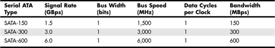
The performance of SATA is impressive, although current hard drive designs can't fully take advantage of its bandwidth. Three variations of the standard have been proposed, and they all use the same cables and connectors; they differ only in transfer rate performance. Currently, only the first two speeds are available, with higher speeds coming in the future. Table 6.9 shows the specifications for the current and future proposed SATA versions; the next-generation 300MBps version was introduced in 2005, and the 600MBps version is expected in 2007.
Table 6.9 SATA Transfer Modes
Note
Extensions to Serial ATA 1.0a (formerly called SATA II) is not the same as SATA 3GB/sec. While 3GB/sec is the standard transfer rate for Extensions to SATA 1.0a, other parts of the extended specifications might or might not be supported by a particular drive. See "ATA8-AST," p. 429, for more about extended SATA specifications.
From Table 6.9, you can see that SATA sends data only a single bit at a time. The cable used has only seven wires (four signal and three ground) and is a very thin design, with keyed connectors only 14mm (0.55-inch) wide on each end. This eliminates problems with airflow compared to the wider PATA ribbon cables. Each cable has connectors only at each end, and each cable connects the device directly to the host adapter (typically on the motherboard). There are no master/slave settings because each cable supports only a single device. The cable ends are interchangeable; the connector on the motherboard is the same as on the device, and both cable ends are identical. Maximum SATA cable length is 1 meter, which is considerably longer than the 18-inch maximum for PATA. Even with this thinner, longer, and less-expensive cable, you initially get transfer rates of 150MBps (nearly 13% greater than those of PATA/133). Extensions to SATA 1.0a supports 300MBps, and even 600MBps is possible.
SATA uses a special encoding scheme called 8B/10B to encode and decode data sent along the cable. The 8B/10B transmission code was originally developed (and patented) by IBM in the early 1980s for use in high-speed data communications. This encoding scheme is now used by many high-speed data transmission standards, including Gigabit Ethernet, Fibre Channel, and FireWire. The main purpose of the 8B/10B encoding scheme is to guarantee that there are never more than four 0s (or 1s) transmitted consecutively. This is a form of run length limited (RLL) encoding called RLL 0,4, in which the 0 represents the minimum and the 4 represents the maximum number of consecutive 0s in each encoded character.
8B/10B encoding also ensures that there are never more than six or fewer than four 0s (or 1s) in a single encoded 10-bit character. Because 1s and 0s are sent as voltage changes on a wire, this ensures that the spacing between the voltage transitions sent by the transmitter is fairly balanced, with a more regular and steady stream of pulses. This presents a steadier load on the circuits, increasing reliability. The conversion from 8-bit data to 10-bit encoded characters for transmission leaves several 10-bit patterns unused. Many of these additional patterns are used to provide flow control, delimit packets of data, perform error checking, or perform other special functions.
SATA Cables and Connectors
The physical transmission scheme for SATA uses differential NRZ (nonreturn to zero). This uses a balanced pair of wires, each carrying ±0.25V. The signals are sent differentially: If one wire in the pair carries +0.25V, the other wire carries -0.25V, where the differential voltage between the two wires is always 0.5V. So, for a given voltage waveform, the opposite voltage waveform is sent along the adjacent wire. Differential transmission minimizes electromagnetic radiation and makes the signals easier to read on the receiving end.
A 15-pin power cable and power connector is optional with SATA, providing 3.3V power in addition to the 5V and 12V provided via the industry-standard 4-pin device power connectors. Although it has 15 pins, this new power connector design is only 24mm in diameter. With 3 pins designated for each of the 3.3V, 5V, and 12V power levels, enough capacity exists for up to 4.5 amps of current at each voltage, which is plenty for even the most power-hungry drives. For compatibility with existing power supplies, SATA drives can be made with the original, standard 4-pin device power connector or the new 15-pin SATA power connector—or both. If the drive doesn't have the type of connector you need, you can get an adapter to convert from one type to the other.
Figure 6.9 shows what SATA signal and power connectors look like.
Figure 6.9 SATA signal and power connectors on a typical SATA hard drive.
Figure 6.10 shows SATA and PATA host adapters on a typical motherboard.
Figure 6.10 A motherboard with SATA and PATA host adapters.
The pinouts for the SATA data and optional power connectors are shown in Tables 6.10 and 6.11, respectively.
Table 6.10 SATA Data Connector Pinout1,2
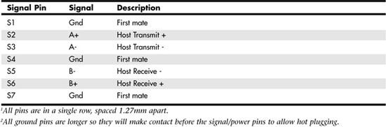
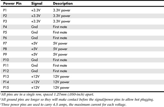
Table 6.11 SATA Optional Power Connector Pinout1-3
SATA Configuration
Configuring SATA devices is also much simpler than configuring PATA devices because the master/slave or cable select jumper settings used with PATA are not necessary.
BIOS Setup for SATA drives is also quite simple. Because SATA is based on ATA, autodetection of drive settings on systems with SATA connectors is performed in the same way as on PATA systems. Depending on the system, SATA interfaces might be enabled by default or might need to be enabled in the BIOS Setup program.
![]() See "The Integrated Device Configuration Submenu," p. 301.
See "The Integrated Device Configuration Submenu," p. 301.
Although add-on SATA host adapters and converters for connecting PATA drives to SATA motherboards are available for desktop PCs, they aren't recommended for servers because these adapters can fail or become disconnected from SATA data cables. This problem can lead to lower reliability, something most server environments cannot afford to leave to chance.
Most recent servers and server motherboards now feature two or more integrated SATA host adapters.
ATA8-AST
As with PATA, SATA was designed to be the primary storage interface used inside a PC and was not initially designed to be used as an external interface. However, with the Extensions to SATA 1.0a (formerly known as SATA II)—and also known as ATA8-AST—now under development, SATA will evolve to include external connections, storage enclosures with multiple drives, and port multipliers that allow up to 15 SATA drives to be connected to a single SATA port. The external connection is designed to support four lanes, with 300MBps per lane, for a total of 1200MBps. This competes with external SCSI for RAID enclosures but most likely won't compete with general-purpose high-speed external device interfaces, such as USB 2.0 and IEEE 1394 (i.LINK/FireWire). Because of the lower cost and smaller size of the internal cables, there is little doubt that SATA will replace PATA in both desktop and laptop systems over the next few years. It could also become common in servers as another way to connect high-performance external drives.
You don't need to wait for ATA8-AST to be formally adopted to enjoy some of its benefits. Some current SATA hardware supports the following ATA8-AST features:
- Native command queuing
- A 300MBps maximum transfer rate
- Hot-swapping
Note that both the host adapter and drive must support a particular ATA8-AST feature in order for it to be used.
Advanced Host Controller Interface
SATA was designed not only as a replacement for PATA but also as an interface that would evolve into something with many more capabilities and features than its predecessor. Initially, compatibility with PATA was one of the most important features of SATA because it enabled a smooth and easy transition from one to the other. This compatibility extends to the driver level, allowing SATA devices to use the same BIOS-level drivers and software as legacy PATA devices.
Although the intent of SATA was to allow an easy transition from PATA, it was also designed to allow future growth and expansion of capabilities. To accomplish this, an enhanced software interface called the Advanced Host Controller Interface (AHCI) was initially developed by the AHCI Contributor Group, a group chaired by Intel and originally consisting of AMD, Dell, Marvell, Maxtor, Microsoft, Red Hat, Seagate, and StorageGear. The AHCI Contributor Group released a preliminary version of AHCI v0.95 in May 2003 and released the final specification in 2004.
AHCI provides a standard, high-performance interface to system driver/operating system software for discovering and implementing such advanced SATA features as command queuing, hot-swapping, and power management. AHCI was integrated into SATA-supporting chipsets in 2004 and is supported by AHCI drivers for Windows. ACHI features are included in ATA8-AST.
SATA Transfer Modes
SATA transfers data in a completely different manner from PATA. As indicated previously, the transfer rates are 150MBps, 300MBps, and 600MBps, with most drives today using the 150MBps rate. However, because SATA is designed to be backward compatible with PATA, some confusion can result because SATA drives can report and emulate PATA mode settings for backward compatibility.
For example, many motherboards detect and report a SATA drive as supporting UDMA Mode 5 (ATA/100), which is a PATA mode that operates at 100MBps. This is obviously incorrect because even the slowest SATA mode (SATA-150) is 150MBps, and UDMA modes simply do not apply to SATA drives.
PATA and SATA are completely different electrical and physical specifications, but SATA does emulate PATA in a way that makes it completely software transparent. In fact, the PATA emulation in SATA specifically conforms to the ATA-5 specification.
This is especially apparent in the IDENTIFY DEVICE command used by the autodetect routines in the BIOS to read the drive parameters. The SATA specification indicates that many of the items returned by IDENTIFY DEVICE are to be set as indicated for ATA-5/ATAPI, including available UDMA modes and settings.
SATA was designed to be fully software compatible with ATA-5/ATAPI, which is why a SATA drive can report in some ways as if it were PATA or running in PATA modes, even though it isn't.
ATA Features
The ATA standards have gone a long way toward eliminating incompatibilities and problems with interfacing IDE drives to ISA/PCI bus systems. The ATA specifications define the signals on the 40-pin connector, the functions and timings of these signals, cable specifications, and so on. The following sections cover ATA commands; the host protected area used for system recovery software; and ATAPI interfacing for optical, removable-media, and tape drives.
ATA Commands
One of the best features of the ATA interface is the enhanced command set. The ATA interface was modeled after the WD1003 controller that IBM used in the original AT system. All ATA drives must support the original Western Digital (WD) command set (eight commands), with no exceptions, which is why ATA drives are so easy to install in systems today. All IBM-compatible systems have built-in ROM BIOS support for the WD1003, so they essentially support ATA as well.
In addition to supporting all the WD1003 commands, the ATA specification added numerous other commands to enhance performance and capabilities. These commands are an optional part of the ATA interface, but several of them are used in most drives available today and are very important to the performance and use of ATA drives in general.
Perhaps the most important is the Identify Drive command. This command causes the drive to transmit a 512-byte block of data that provides all details about the drive. Through this command, any program (including the system BIOS) can find out exactly which type of drive is connected, including the drive manufacturer, the model number, the operating parameters, and even the serial number of the drive. Many modern BIOSes use this information to automatically receive and enter the drive's parameters into CMOS memory, eliminating the need for the user to enter these parameters manually during system configuration. This arrangement helps prevent mistakes that can later lead to data loss when the user no longer remembers what parameters he or she used during setup.
The Identify Drive data can tell you many things about your drive, including the following:
- The number of logical block addresses available, using LBA mode
- The number of physical cylinders, heads, and sectors available in P-CHS mode
- The number of logical cylinders, heads, and sectors in the current translation L-CHS mode
- The transfer modes (and speeds) supported
- The manufacturer and model number
- The internal firmware revision
- The serial number
- The buffer type/size, indicating sector buffering or caching capabilities
Two other important commands are Read Multiple and Write Multiple. These commands permit multiple-sector data transfers and, when combined with block-mode PIO capabilities in the system, can result in incredible data transfer rates that are many times faster than single-sector PIO transfers. Some older systems require you to select the correct number of sectors supported by the drive, but most recent systems automatically determine this information for you. Note that some BIOSs refer to Read Multiple as "block mode."
Many other enhanced commands are available, and there is even room for a given drive manufacturer to implement vendor-unique commands. Certain vendors often create such commands for their own unique features. Often, vendor-unique commands control features such as low-level formatting and defect management. This is why low-level format (LLF) programs can be so specific to a particular manufacturer's ATA drives and why many manufacturers make their own LLF programs available.
The Host Protected Area
Most PCs sold today include some form of automated product recovery or restoration feature that allows a user to easily restore the operating system and other software on the system to the state it was in when the system was new. Originally, this was accomplished via one or more product recovery CDs containing automated scripts that reinstalled all the software that came preinstalled on the system when it was new.
Unfortunately, the CDs could be lost or damaged, they were often problematic to use, and including them by default cost manufacturers a lot of money. This prompted PC manufacturers to move the recovery software to a hidden partition of the boot hard drive. Although this wastes some space on the drive, the recovery software normally fits on from one to four CDs, which occupies 1GB–3GB of drive space. With 60GB or larger drives, this amounts to 5% or less of the total space. Still, storing this information on the hidden partition was less than satisfactory because the partition could easily be damaged or overwritten by partitioning software or other utilities, so there was no way to make it secure.
In 1996, Gateway proposed a change to the ATA-4 standard under development that would allow a space called the host protected area (HPA) to be reserved on a drive. This change was ratified, and the HPA feature set was incorporated into the ATA-4 specification that was published in 1998. A separate BIOS firmware interface specification called Protected Area Run Time Interface Extension Services (PARTIES) was initiated in 1999 that defined services an operating system could use to access the HPA. The PARTIES standard was completed and published in 2001 as NCITS 346-2001, "Protected Area Run Time Interface Extension Services."
The HPA works by using the optional ATA SET MAX ADDRESS command to make the drive appear to the system as a slightly smaller drive. Anything from the new max address (that is, the newly reported end of the drive) to the true end of the drive is considered the HPA and is accessible only using PARTIES commands. This is more secure than having a hidden partition because any data past the end of the drive simply cannot be seen by any normal application, or even a partitioning utility such as PartitionMagic or Partition Commander. Still, if you want to remove the HPA, you can use some options in the BIOS Setup or separate commands to reset the max address, thus exposing the HPA. At that point, you can run a utility such as PartitionMagic or Partition Commander to resize the adjacent partition to include the extra space that was formerly hidden and unavailable.
Most new systems using Phoenix FirstBIOS come with their recovery software and diagnostics in the HPA because this is part of the new Phoenix FirstBIOS core managed environment (CME), which is used by a large number of OEMs (including IBM) on most desktop and laptop systems starting in 2003.
ATAPI
The ATAPI standard is designed to provide the commands necessary for devices such as CD-ROM and DVD drives, removable media drives such as SuperDisk and Zip drives, and tape drives that plug in to an ordinary ATA (IDE) connector. The principal advantage of ATAPI hardware is that it's cheap and works with your current adapter. All modern ATA CD-ROM drives support the ATAPI protocols, and generally the terms ATA and ATAPI are synonymous. In other words, an ATAPI CD-ROM is an ATA CD-ROM and vice versa.
Caution
Starting in 1998, most systems began supporting the Phoenix El Torito specification, which enables booting from ATAPI CD or DVD drives. Systems without El Torito support in the BIOS can't boot from an ATAPI CD or DVD drive. Even with ATAPI support in the BIOS, you must still load a driver to use ATAPI under DOS or Windows; an ATAPI driver is supplied with all recent Windows and Linux versions. Most recent server operating systems, including Windows 2000 Server and Windows Server 2003, include bootable CDs for easy installation.
You should normally keep ATA devices you will be accessing simultaneously on separate channels. Because ATA does not typically support overlapping access, when one drive is being accessed on a given channel, the other drive on the same channel can't be accessed. By keeping the CD-ROM or DVD drive and hard disk on separate channels, you can more effectively overlap accessing between them.
This is easy to do if your server uses SCSI or SATA hard disks for storage and has a single CD or DVD drive. The CD or DVD drive is the only ATA device in the system, so it cannot interfere with hard disk storage. However, this can be trickier on a server that uses ATA drives for both hard disk storage and optical drives. In such cases, you need to be sure to use one ATA host adapter for the hard disk and a separate one for the CD or DVD drive. If you are using PATA drives in a RAID array, they are connected to a special ATA host adapter designated as a RAID adapter. You can use the non-RAID ATA adapter for the CD or DVD drive.
If you must put a PATA hard disk and CD or DVD drive on the same cable, you should set PATA hard drives as masters (Device 0) and parallel ATAPI drives as slaves (Device 1).
ATA Drive Capacity Limitations
ATA interface versions up through ATA-5 suffered from a drive capacity limitation of about 137GB (billion bytes). Depending on the BIOS used, this limitation could be further reduced to 8.4GB, or even as low as 528MB. This is due to limitations in both the BIOS and the ATA interface, which, when combined, create even further limitations. To understand these limits, you have to look at the BIOS (software) and ATA (hardware) interfaces together.
Note
In addition to the BIOS/ATA limitations discussed in this section, various operating system limitations also exist, as described later in this chapter.
When dealing with ATA drives, you face limitations of the ATA interface itself as well as limitations of the BIOS interface used to talk to the drive. A summary of these limitations is shown in Table 6.12.
Table 6.12 ATA/IDE Capacity Limitations for Various Sector Addressing Methods1

The following sections detail the differences between the various sector addressing methods and the limitations related to using them.
Prefixes for Decimal and Binary Multiples
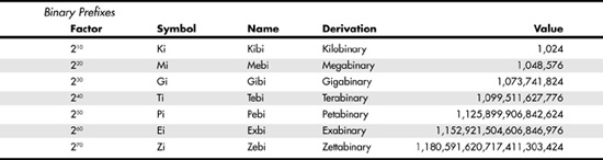
You may be unfamiliar with the MiB (mebibyte), GiB (gibibyte), and so on designations used in this section and throughout the rest of the book. They are part of a standard designed to eliminate confusion between decimal- and binary-based multiples, especially in computer systems. Standard SI (system international, or metric system) units are based on multiples of 10. This worked well for most things, but not for computers, which operate in a binary world, where most numbers are based on powers of 2. This has resulted in different meanings being assigned to the same prefix; for example 1KB (kilobyte) could mean either 1,000 (103) bytes or 1,024 (210) bytes. To eliminate confusion, in December 1998 the International Electrotechnical Commission (IEC) approved as an international standard the prefix names and symbols for binary multiples used in data processing and transmission. Some of these prefixes are shown in Table 6.13.
Table 6.13 Standard Prefix Names and Symbols for Binary Multiples
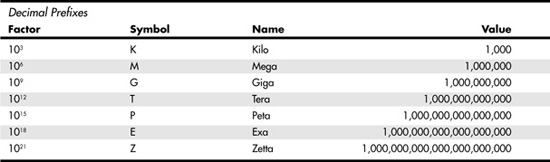
Under the IEC standard terminology, 1MB (megabyte) would be 1,000,000 bytes, whereas 1MiB (mebibyte) would be 1,048,576 bytes.
Note
For more information on these industry-standard decimal and binary prefixes, check out the National Institute of Standards and Technology (NIST) website, at http://physics.nist.gov/cuu/Units/prefixes.html.
BIOS Limitations
Motherboard ROM BIOS has been updated throughout the years to support larger and larger drives. Table 6.14 shows the most important relative dates when drive capacity limits were changed.
Table 6.14 Dates of Changes to Drive Capacity Limitations in the ROM BIOS
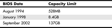

BIOSes dated September 2002 or newer should support drives larger than 137GB. Table 6.14 gives only general guidelines; to accurately determine the capacity limit for a specific system, you should check with your motherboard manufacturer. You can also use the BIOS Wizard utility at www.unicore.com/bioswiz/index2.html, which can tell you the BIOS date from your system and specifically whether your system supports the Enhanced Disk Drive (EDD) specification (which means drives over 8.4GB).
Generally, any server currently in use should support at least the EDD (8.4GB–137GB) standard. You should upgrade the motherboard BIOS on a server that cannot support a hard disk greater than 8.4GB. Although other fixes such as using a BIOS upgrade card with onboard ATA/IDE ports or a software fix have been used on desktop systems, they are not suitable for servers.
Increasing ATA Drive Size: CHS and LBA Modes
There are two primary methods to address (or number) sectors on an ATA drive. The first method is called CHS (cylinder head sector), after the three respective coordinate numbers used to address each sector of the drive. The second method is called LBA (logical block address), and it uses a single number to address each sector on a drive. CHS was derived from the way drives were physically constructed (and is how they work internally), whereas LBA evolved as a simpler and more logical way to number the sectors, regardless of the internal physical construction.
CHS access limits the size of a hard disk to 528MB (decimal) or 504MiB. To overcome this limitation, the EDD specification was released by BIOS maker Phoenix Technologies in 1994. It specifies three ways to overcome the 528MB CHS barrier:
- Use BIOS INT13h extensions supporting 64-bit LBA
- Bit-shift geometric CHS translation
- LBA-assist geometric CHS translation
The method for dealing with the CHS problem was called translation because it enabled additional subroutines in the BIOS to translate CHS parameters from ATA maximums to BIOS maximums (and vice versa). In an effort to make its methods standard among the entire PC industry, Phoenix released the EDD document publicly and allowed the technology to be used free of charge, even among its competitors, such as American Megatrends (AMI) and Award. The T13 committee in charge of ATA subsequently adopted the EDD standard and incorporated it into official ATA documents.
Although a few vendors standardized on the bit-shift method of translation (also known as Large, or Extended, CHS in BIOS Setup), LBA-assist (better known as LBA mode) became the de facto standard for translating drives greater than 528MB. Note that a BIOS configured in LBA mode cannot properly read a drive prepared using Large mode because the methods of capacity translation are different.
Problems with the implementation of Extended CHS translation caused several additional drive capacity barriers, including the 2.1GB barrier and the 4.2GB barrier. LBA mode avoids these problems.
For drives over 8.4GB, CHS geometry is no longer translated into LBA geometry, but the drive is accessed in a purely LBA mode. This feature was introduced in 1998 as part of the EDD standard.
The 8.4GB Barrier
Although CHS translation breaks the 528MB barrier, it runs into another barrier at 8.4GB. Supporting drives larger than 8.4GB requires leaving CHS behind and changing to LBA addressing at the BIOS level. Although, the ATA interface had always supported LBA addressing, even in the original ATA-1 specification, it had been optional, but the main problem was that there was no LBA support at the BIOS interface level. You could set LBA-assist translation in the BIOS Setup, but all that did was convert the drive LBA numbers to CHS numbers at the BIOS interface level.
Phoenix Technologies recognized that the BIOS interface needed to move from CHS to LBA early on and, beginning in 1994, it published the BIOS Enhanced Disk Drive Specification (EDD) specification, which addressed this problem with new extended INT13h BIOS services that worked with LBA rather than with CHS addresses.
To ensure industrywide support and compatibility for these new BIOS functions, in 1996, Phoenix turned this document over to the InterNational Committee on Information Technology Standards (INCITS) T13 technical committee for further enhancement and certification as the EDD standard. Starting in 1998, most of the other BIOS manufacturers began installing EDD support in their BIOSs, enabling BIOS-level LBA mode support for ATA drives larger than 8.4GB. This support arrived just in time because ATA drives of that size and larger became available the same year.
The EDD specification describes new extended INT13h BIOS commands that allow LBA addressing up to 264 sectors, which results in a theoretical maximum capacity of more than 9.44ZB (zettabytes, or quadrillion bytes). That is the same as saying 9.44 trillion GB: 9.441021 bytes, or, to be more precise, 9,444,732,965,739,290,427,392 bytes! This is theoretical capacity because even though by 1998 the BIOS could handle up to 264 sectors, ATA drives were still using only 28-bit addressing (228 sectors) at the ATA interface level. This limited an ATA drive to 268,435,456 sectors, which was a capacity of 137,438,953,472 bytes, or 137.44GB. Thus, the 8.4GB barrier had been broken, but another barrier remained at 137GB because of the 28-bit LBA addressing used in the ATA interface.
By using the new extended INT13h 64-bit LBA mode commands at the BIOS level as well as the existing 28-bit LBA mode commands at the ATA level, no translation would be required, and the LBA numbers would be passed unchanged. The combination of LBA at the BIOS and ATA interface levels meant that the clumsy CHS addressing could finally be laid to rest. This also means that when you install an ATA drive larger than 8.4GB in a PC that has an EDD-capable BIOS (1998 or newer), both the BIOS and the drive are automatically set to use LBA mode.
An interesting quirk is that to allow backward compatibility when you boot an older operating system that doesn't support LBA mode addressing (DOS or the original release of Windows 95, for example), most drives larger than 8.4GB report 16,383 cylinders, 16 heads, and 63 sectors per track, which is 8.4GB. For example, this enables a 120GB drive to be seen as an 8.4GB drive by older BIOSes or operating systems. It sounds strange, but having a 120GB drive being recognized as an 8.4GB drive is better than not having it work at all. (If you want to install a drive larger than 8.4GB into a system dated before 1998, the recommended solution is a motherboard BIOS upgrade.)
The 137GB Barrier and Beyond
By 2001, the 137GB barrier had become a problem because 3.5-inch hard drives were poised to breach that capacity level. The solution came in the form of ATA-6, which was being developed during that year. To enable the addressing of drives of greater capacity, ATA-6 upgraded the LBA functions from using 28-bit numbers to using larger 48-bit numbers.
The ATA-6 specification extends the LBA interface such that it can use 48-bit sector addressing. This means that the maximum capacity is increased to 248 (281,474,976,710,656) total sectors. Each sector stores 512 bytes, so this results in a maximum drive capacity of just over 144PB (petabytes, or quadrillion bytes)—which should be sufficient for years to come.
Because, according to Moore's Law, hard disk drives have been doubling in capacity every 1.5–2 years, and considering that 200GB+ ATA drives were available in late 2003, it will probably take us until between the years 2031 and 2041 to reach the 144PB barrier (assuming that hard disk technology hasn't been completely replaced by then).
The 137GB barrier has proven a bit more complicated than previous barriers because, in addition to considering BIOS issues, we must also consider operating system issues. Internal ATA drives larger than 137GB require 48-bit LBA (logical block address) support. This support absolutely needs to be provided in the OS, but it can also be provided in the BIOS. It is best if both the OS and BIOS support it, but it can be made to work if only the OS does.
Windows versions that are suitable for server use and include 48-bit LBA support include the following:
- Windows 2000 Server with Service Pack 3 (SP3) or later; SP4 or later is recommended for best performance
- Windows XP with SP1 or later
- Windows Server 2003
To have 48-bit LBA support in the BIOS requires either of the following:
- A motherboard BIOS with 48-bit LBA support (most of those dated September 2002 or later)
- An ATA host adapter card with onboard BIOS that includes 48-bit LBA support
If your motherboard BIOS does not have LBA support and an update is not available from your motherboard manufacturer, you can use a card to provide 48-bit LBA support. Vendors that offer 48-bit LBA support plus additional ATA, SATA, or ATA/SATA RAID host adapters include SIIG (www.siig.com) and Promise Technology (www.promisetech.com). These cards provide 48-bit LBA support for connected hard disk drives.
Note that if you have both BIOS and OS support, you can simply install and use the drive as you would any other. If you have no BIOS support but you do have OS support, portions of the drive past 137GB are not recognized or accessible until the OS is loaded. If you are installing the OS to a blank hard drive and booting from an original Windows XP (pre-SP1) CD-ROM or earlier, you need to partition and install up to the first 137GB of the drive at installation time. After installing the OS and then the SP1 update, you can either partition the remainder of the drive, using standard partitioning software, or use a third-party partitioning program such as PartitionMagic or Partition Commander to resize the first partition to use the full drive. If you are booting from a Windows XP SP1 or later CD-ROM, you can recognize and access the entire drive during the OS installation and partition the entire drive as a single partition greater than 137GB, if you want.
Finally, you should keep in mind that the versions of Windows 2000 and Windows XP prior to those listed earlier in this section do not provide native support for ATA (PATA and SATA) hard drives that are larger than 137GB. However, Windows Server 2003 has native support for 48-bit LBA.
Operating System and Other Software Limitations
If you use older software, including utilities, applications, or even operating systems that rely exclusively on CHS parameters, they will see all drives over 8.4GB as 8.4GB only. In this case, you need not only a newer BIOS but also newer software designed to handle the direct LBA addressing to work with drives over 8.4GB.
Table 6.15 lists server operating system limitations with respect to drives over 8.4GB.
Table 6.15 Server Operating System Limitations

In the case of operating systems that support drives over 8.4GB, the maximum drive size limitations are dependent on the BIOS and hard drive interface standard, not on the OS. In those cases, other limitations come into play for the volumes (partitions) and files that can be created and managed by the various operating systems. These limitations are dependent on not only the operating system involved but also the file system used for the volume. Table 6.16 shows the minimum and maximum volume (partition) size and file size limitations of the various Windows server operating systems. As noted in the previous section, the original version of Windows XP, as well as Windows 2000/NT or Windows 95, 98, or Me, does not currently provide native support for ATA hard drives that are larger than 137GB. You need to use Windows XP and ensure that you have SP1 or later installed to use an ATA drive over 137GB. This does not affect drives using USB, FireWire, SCSI, or other interfaces.
Table 6.16 Operating System Volume/File Size Limitations, by File System1

Common ATA Configurations for Server Platforms
Although SCSI hard disks have traditionally been used in midrange and high-end server platforms, ATA-based hard disks continue to be popular in entry-level servers. The superior performance and easier configuration offered by SATA hard disks make them a suitable choice for both entry-level and many midrange server implementations. The following sections provide recommendations for using ATA drives in a server platform.
ATA/ATAPI Configurations for Server Platforms
If you decide to use PATA hard disks in an entry-level server, you need to configure your server as follows:
- Connect the hard disk to the primary PATA (40-pin) connector on the motherboard.
- Connect the CD or DVD optical drive used for program loading or for creating backups to the secondary PATA connector on the motherboard.
- Choose a hard disk with a 7200RPM spin rate and an 8MB cache for best performance.
- Use 80-wire UDMA cables on both drives to permit maximum speed operation.
- Be sure to install the appropriate UDMA drivers in the operating system.
Note that most commercial entry-level servers no longer use PATA hard disks, although ATAPI CD and DVD drives continue to be popular.
SATA Configurations for Server Platforms
As noted earlier in this chapter, SATA drives have largely replaced PATA hard disks in entry-level servers, and they have made inroads into the midrange server market as well.
To improve reliability and performance, you should consider using SATA hard disks that meet the following standards:
- 7200RPM or 10,000RPM spin rates; drives with 10,000RPM spin rates are recommended when access time is more important than high capacity (10,000RPM spin rate drives are currently limited to 150GB per drive, while 7200RPM drives are available in capacities up to 500GB)
- 8MB or larger cache; some 16MB cache drives are now available
- Support for command queuing (tagged or native) to improve throughput; the type of command queuing supported must also be supported by the SATA host adapter used by the system
- Designed for higher reliability; look at factors such as MTBF, thermal management, and warranty
Each SATA hard disk uses a separate host adapter.
ATA/SATA RAID Configurations for Server Platforms
RAID, which stands for redundant array of independent (or inexpensive) disks, was designed to improve the fault tolerance and performance of computer storage systems. RAID was first developed at the University of California at Berkeley in 1987, and it was designed so that a group of smaller, less expensive drives could be interconnected with special hardware and software to make them appear as a single, larger drive to the system. By using multiple drives to act as one drive, fault tolerance and performance could be increased.
Initially, RAID was conceived to simply enable all the individual drives in the array to work together as a single, larger drive with the combined storage space of all the individual drives added together. However, this actually reduced reliability and didn't do much for performance, either. For example, if you had four drives connected in an array acting as one drive, you would be four times as likely to experience a drive failure than if you used just a single, larger drive. To improve its reliability and performance, the Berkeley scientists proposed six levels (corresponding to different methods) of RAID. These levels provide varying emphasis on fault tolerance (reliability), storage capacity, or performance—or a combination of the three.
An organization called the RAID Advisory Board (RAB) was formed in July 1992 to standardize, classify, and educate on the subject of RAID. RAB has developed specifications for RAID, a conformance program for the various RAID levels, and a classification program for RAID hardware.
Currently, RAB defines seven standard RAID levels, RAID 0–6. RAID is typically implemented by a RAID controller board, although software-only implementations are possible (but not recommended). The levels are as follows:
- RAID Level 0: Striping—File data is written simultaneously to multiple drives in the array, which act as a single, larger drive. This level offers high read/write performance but very low reliability. It requires a minimum of two drives.
- RAID Level 1: Mirroring—Data written to one drive is duplicated on another, providing excellent fault tolerance (if one drive fails, the other is used and no data is lost) but no real increase in performance compared to using a single drive. It requires a minimum of two drives (and has the same capacity as one drive).
- RAID Level 2: Bit-level ECC—Data is split 1 bit at a time across multiple drives, and error correction codes (ECCs) are written to other drives. It is intended for storage devices that do not incorporate ECC internally (all SCSI and ATA drives have internal ECC). It provides high data rates with good fault tolerance, but large numbers of drives are required, and no commercial RAID 2 controllers or drives without ECC are available on the market.
- RAID Level 3: Striped with parity—This level combines RAID Level 0 striping with an additional drive that is used for parity information. This RAID level is really an adaptation of RAID Level 0 that sacrifices some capacity, for the same number of drives. However, it also achieves a high level of data integrity or fault tolerance because data can usually be rebuilt if one drive fails. It requires a minimum of three drives (two or more for data and one for parity).
- RAID Level 4: Blocked data with parity—This level is similar to RAID 3, except data is written in larger blocks to the independent drives, offering faster read performance with larger files. It requires a minimum of three drives (two or more for data and one for parity).
- RAID Level 5: Blocked data with distributed parity—This level is similar to RAID 4, but it offers improved performance by distributing the parity stripes over a series of hard drives. It requires a minimum of three drives (two or more for data and one for parity).
- RAID Level 6: Blocked data with double distributed parity—This level is similarto RAID 5, except parity information is written twice, using two different parity schemes, to provide even better fault tolerance in case of multiple drive failures. It requires a minimum of four drives (two or more for data and two for parity).
- RAID Level 10 (RAID 1+ 0): Striping plus mirroring—This level is a combination of RAID 1 (mirroring) and RAID 0 (striping). Provides higher performance than RAID 1. It requires a minimum of four drives (two for mirroring; two for striping).
Additional RAID levels exist that are not supported by RAB but that are instead custom implementations by specific companies.
Note
Note that a higher RAID level number doesn't necessarily mean increased performance or fault tolerance; the numbered order of the RAID levels is entirely arbitrary.
At one time, virtually all RAID controllers were SCSI based, meaning that they used SCSI drives. For a professional setup, SCSI RAID is definitely the best choice because it combines the advantages of RAID with the advantages of SCSI—an interface that was already designed to support multiple drives. Now, however, ATA RAID controllers are available that allow for even less expensive RAID implementations. These ATA RAID controllers are typically used in single-user systems for performance rather than reliability increases.
Most ATA RAID implementations are much simpler than the professional SCSI RAID adapters used on network file servers. ATA RAID is designed more for an individual who is seeking performance or simple drive mirroring for redundancy. When they're set up for performance, ATA RAID adapters run RAID Level 0, which incorporates data striping. Unfortunately, RAID 0 also sacrifices reliability, such that if one drive fails, all data is lost. With RAID 0, performance scales up with the number of drives you add to the array. If you use four drives, you don't necessarily have four times the performance of a single drive, but you can get close to that for sustained transfers. Some overhead is still involved in the controller performing the striping, and issues still exist with latency—that is, how long it takes to find the data—but performance with RAID is higher than what any single drive could normally achieve.
When they're set up for reliability, ATA RAID adapters generally run RAID Level 1, which is simple drive mirroring. All data written to one drive is written to the other. If one drive fails, the system can continue to work on the other drive. Unfortunately, this does not increase performance at all, and it also means you get to use only half of the available drive capacity. In other words, you must install two drives, but you get to use only one (the other is the mirror). However, in an era of high capacities and low drive prices, this is not a significant issue. If you want to eliminate a lot of bulky cable, consider SATA RAID, which uses the narrow SATA cables shown in Figure 6.1, earlier in this chapter.
Combining performance with fault tolerance requires using one of the other RAID levels, such as RAID Level 3 or RAID Level 5. For example, virtually all professional RAID controllers used in network file servers are designed to use RAID Level 5. Controllers that implement RAID Level 5 are more expensive, and at least three drives must be connected. To improve reliability, but at a lower cost, many of the ATA RAID controllers enable combinations of the RAID levels—such as 0 and 1 combined (also known as RAID 10). This usually requires four drives, two of which are striped together in a RAID Level 0 arrangement, which is then redundantly written to a second set of two drives in a RAID Level 1 arrangement. This enables you to have approximately double the performance of a single drive, and you have a backup set, in case one of the primary sets fails. Many recent servers include four SATA host adapters with RAID functionality, enabling SATA RAID 0+1 implementations.
Today, you can get PATA or SATA RAID controllers from companies such as Arco Computer Products, Iwill, Promise Technology, and HighPoint. A typical low-cost ATA RAID controller enables up to four drives to be attached, and you can run them in RAID Level 0, 1, or 0+1 mode. Remember that performance suffers somewhat when you run two drives (master/slave) on a single PATA channel because only one drive can transfer on the cable at a time, which cuts performance in half. Four-channel PATA RAID cards are available, but most new RAID cards are moving to SATA, which doesn't have the master/slave channel sharing problems of PATA. SATA RAID cards use a separate SATA data channel (cable) for each drive, allowing maximum performance. You should use SATA RAID cards for best performance.
If you are looking for an ATA RAID controller (or a motherboard with an integrated ATA RAID controller), you should look for the following:
- RAID levels supported (most support 0, 1, and 0+1, although some ATA RAID 5 card products are now available)
- Two or four channels (for best performance, you should use four channels with four devices using PATA)
- Support for ATA/100 or ATA/133 speeds for PATA
- Support for 33MHz or 66MHz PCI slots (some servers have 66MHz slots)
- SATA RAID implementations for maximum performance, ease of installation, and reliability
If you want to experiment with RAID inexpensively, you can implement RAID without a custom controller when using certain higher-end (often server-based) operating systems. For example, the Windows NT/2000 and Windows XP or Windows Server 2003 operating systems provide a software implementation for RAID, using both striping and mirroring. In these operating systems, you use the Disk Administrator tool to set up and control the RAID functions, as well as to reconstruct the volume after a failure occurs. Normally, though, if you are building a server and want the ultimate in performance and reliability, you should look for SATA or SCSI RAID controllers that support RAID Level 3 or Level 5.
Tip
The best solutions for RAID are SATA and SATA RAID implementations that are native to the motherboard chipset's South Bridge or I/O controller hub chip. When Windows 2000 Server or Windows Server 2003 is installed on a system with native SATA or SATA RAID support, there is no need to press the F6 key when you're prompted to install a driver from a floppy disk. With add-on SATA and ATA/SATA RAID add-on cards or motherboard implementations using a separate SATA host adapter chip, you must press F6 when prompted to install the appropriate driver from a floppy disk.
The latest type of RAID array, RAIDn, developed by Inostor, a division of Tandberg Data, combines special software that can specify the number of drives used for replacements. A RAIDn array designed to protect against the failure of up to four drives uses only 7 drives (4 for data and 3 for parity), compared to 10 drives for a RAID 5+1 array (4 data, 1 parity; 4 mirrored data; 1 mirrored parity). Currently, RAIDn arrays are available only in Inostor network attached storage (NAS) devices, but RAIDn software is designed to be portable to other operating systems.
![]() For more about RAID, see "Introduction to RAID," p. 600.
For more about RAID, see "Introduction to RAID," p. 600.
Using NAS
As an alternative to expanding internal server storage by adding ATA, SATA, or SCSI hard disks to a server (a concept often referred to as direct attached storage [DAS]), you can connect a network attached storage (NAS) device to your network. Each NAS device has its own IP address, and an NAS device contains one or more hard disks that can be accessed directly from the network.
The first company to develop an NAS device was Auspex, which introduced the first NAS shortly after being founded in 1987. Although the company went bankrupt in June 2003, its technology was sold to other firms. Using NAS devices continues to be a popular method of expanding network storage, and many companies now build NAS devices.
In addition to hard disks, an NAS device contains one or more processors to handle I/O, network, and data storage and retrieval tasks. Although a given NAS device might contain a processor similar to that used by a desktop PC or server, an NAS device is not a PC or a server. Instead, it is a specialized storage appliance.
The benefits of expanding network storage by using an NAS device include the following:
- No server downtime—You can connect an NAS device to the network without disrupting existing servers.
- Easier configuration—In most cases, you can configure the NAS from a web browser on a client PC. The client PC logs in to the NAS device's built-in webserver. Some NAS devices use Windows Storage Server 2003.
- Easy rack-mounting—Many NAS devices fit in a 1U or 2U form factor.
- Easy backup—Some NAS devices, including autoloaders, support direct disk-to-disk or disk-to-tape backups. Some NAS devices can be used as network backup appliances (NBAs) for other servers.
- Wide range of RAID options—RAID options vary by product and vendor, but most vendors offer RAID 0, RAID 1, RAID 0+1, RAID 4, and RAID 5. Some offer additional RAID options.
The following are the shortcomings of NAS storage:
- The speed of storage is limited by the speed of the network—For best results, an NAS should be connected to a Gigabit Ethernet network, with all clients using Gigabit Ethernet adapters.
- As the name implies, NAS is for network storage only—If you use thin clients that remotely store applications, applications must be stored on a server, not on an NAS.
- NAS storage can be more difficult to secure than server-based storage—For maximum protection, NAS devices should be protected by antivirus programs made especially for NAS, such as Symantec AntiVirus ScanEngine. Also, networks that use NAS devices should be protected from public access by firewall devices.
If you need speeds significantly faster than NAS can provide (about 32MBps sustained transfer rate with a Gigabit Ethernet network) and prefer more security options, you should consider a storage area network (SAN) installation.
![]() For more about SANs, see Chapter 12, "Storage Area Networks."
For more about SANs, see Chapter 12, "Storage Area Networks."
Troubleshooting ATA and SATA Hard Disks
ATA and SATA hard disks are more reliable today than in the past, but problems with them can still affect a server's ability to run reliably. Problems can occur during drive configuration and during operation. The following sections describe typical problems and solutions.
CMOS/BIOS, Startup Problems
Some of the most common problems to be aware of during the installation of ATA and SATA hard disks include the following:
- Using the wrong parameters for the hard disk—For reliable installation, you should use the autoconfiguration option in the system BIOS/CMOS Setup program. Doing so ensures that the correct geometry, LBA mode setting, and UDMA mode setting will be used for each drive.
- Failing to enable SATA host adapters—Many systems disable onboard SATA host adapters by default. If you plan to use SATA hard disks connected to onboard SATA host adapters, you must enable the SATA host adapters in the system BIOS/CMOS Setup program.
- Failing to install SATA, SATA RAID, or ATA RAID host adapter drivers during Windows installation—If the host adapter uses a discrete chip on the motherboard or an add-on card (instead of being built into the motherboard's South Bridge or I/O controller hub), Windows will not be able to use the drive if you don't provide the driver when prompted (see Figure 6.11).
Figure 6.11 This prompt appears extremely early in the installation process for Windows Server 2003 as well as Windows 2000 and Windows XP.
![]()
- Disabling onboard SMART detection of hard disk problems—Most recent systems support SMART, as do most system management programs. Making sure SMART is enabled is cheap insurance against hard disk failure.
If you plan to use an onboard RAID array for ATA or SATA hard disks, you need to be sure to follow the system or motherboard vendor's instructions. Many systems with onboard ATA or SATA RAID use a so-called "soft RAID" configuration that requires you to run a RAID Setup application from disk to prepare the RAID array for use.
If you decide to convert a single-drive installation into a RAID array, you need to make sure to make a full backup of the drive first. Although some recent RAID implementations do not wipe out existing data, the possibility of data loss remains.
If your ATA RAID, SATA RAID, or SATA host adapter uses an add-on card host adapter or your motherboard has a separate SATA or SATA/ATA RAID host adapter chip, you should have received a driver floppy disk with your host adapter or motherboard. When you see the prompt to press F6 during the installation of Windows (see Figure 6.11), you need to press F6 and provide the driver disk. Otherwise, the server's SATA, SATA RAID, or ATA RAID host adapter card or onboard host adapter will not work and the drives connected to it cannot be accessed.
If you miss this prompt, you need to restart your computer and restart the installation process, and you will have another chance to provide the needed driver.
BSODs and Other Postinstallation Problems
The notorious blue screen of death (BSOD) or STOP errors associated with serious problems in Windows 2000, Windows Server 2003, and Windows XP are sometimes caused by problems with ATA or SATA hard disks or device drivers. Some of these errors include the following:
- STOP 0x0000000A (IRQL_NOT_LESS_OR_EQUAL)—This error can be caused by a variety of faulty device drivers or firmware problems. If this error occurs after you update ATA or SATA device drivers, you should restart Windows in Safe Mode and roll back to the previous driver.
- STOP 0x0000001E (KMODE_EXCEPTION_NOT_HANDLED)—This error can be caused by running short of disk space. You need to remove unneeded temporary files or outdated system restore files.
- STOP 0x00000024 (NTFS_FILE_SYSTEM)—This error can be caused by problems with ATA, SATA, or SCSI hard disks, cables, or drivers. You need to replace cables and check drivers. You should use error checking (CHKDSK) to test all hard disks.
- STOP 0x0000002E (DATA_BUS_ERROR)—One of the less likely causes for this error is hard disk corruption. You should use error checking (CHKDSK) and enable the option to repair file system errors to test all hard disks.
- STOP 0x00000077 (KERNEL_STACK_INPAGE_ERROR)—You can use CHKDSK (error checking) on the paging hard disk to check for bad sectors.
- STOP 0x0000007A (KERNEL_STACK_DATA_ERROR)—You can check the I/O status code to help troubleshoot this error:
- STATUS_DEVICE-DATA_ERROR—You should use CHKDSK (error checking) on the paging hard disk to check for bad sectors.
- STATUS_DEVICE_NOT_CONNECTED—You should check the BIOS/CMOS configuration for hard disks; you should also check drive power and data cables.
- STATUS_IO_DEVICE_ERROR—You should check the host adapter configuration; you should also check drive power and data cables. This error can also be caused by failing to install the appropriate driver after pressing F6.
![]() See "CMOS/BIOS, Startup Problems," p. 444, for details.
See "CMOS/BIOS, Startup Problems," p. 444, for details.
- STOP 0x0000007B (INACCESSIBLE_BOOT_DEVICE)—Windows can't locate the system partition or boot volume. You need to make sure correct drivers for ATA or SATA host adapters have been loaded.
- STOP 0x000000ED (UNMOUNTABLE_BOOT_VOLUME)—This error can be caused by trying to use a 40-wire ATA/IDE cable with a drive configured in firmware or system BIOS/CMOS to use 80-wire (UDMA 66 or faster) mode. You should use an 80-wire UDMA 66 cable.
Note that most of these errors can also be caused by other problems. For full details on each error and suggested solutions, go to http://support.microsoft.com and look up the specific STOP error.
If you use SMART-enabled hard disks and have SMART monitoring enabled in the system BIOS, you should back up and replace any drives that display SMART errors during startup or during operation. Note that you must have system management software that supports SMART monitoring to see errors after server startup.