Chapter 12
Storage Area Networks
A storage area network (SAN) is a network of managed, shared, and distributed storage assets—a network of storage servers, if you will. You might infer that a SAN must have its own dedicated network, and for the most part, you would be correct, at least historically. As described in the Chapter 11, "Disk Subsystems," SANs are built with Fibre Channel switches and hubs, and the nodes are linked with either fiber-optic or coaxial cabling.
That storage network interfaces to a local area network (LAN) of servers and clients, where each server and client on the LAN connects to the SAN either through a file server or with a connection to the SAN itself. As Ethernet has gotten faster, and as the storage industry has found ways to permit hosts to transfer large amounts of data by offloading the processing required, there has been more and more interest in eliminating separate storage networks and unifying a whole networking enterprise. There's no hard-and-fast definition of what constitutes a SAN—only that it achieves the desired aim of making storage available to clients.
Most SANs are built to network vast amounts of storage data. When you consider that a large EMC, Hitachi Data Systems, IBM, or Hewlett-Packard storage server can contain hundreds of terabytes of data stored on as many as a couple hundred disk drives and that many storage deployments network petabytes of data, SANs make a lot of sense. There's an enormous amount of money invested in storage (often it's more than 50% of the IT budget), and it's important to get the most out of that investment.
Note
For a more in-depth discussion of SANs, see Using Storage Area Networks Special Edition.
In an era when you can create a RAID array of more than a terabyte from three 400GB hard drives or purchase a network attached storage (NAS) appliance such as LaCie's Bigger Disk Extreme (1.8TB for $1,700), the time has come to consider applying the principles of storage area networking to your own servers and your own network. If you find yourself backing up computers at night in order to keep your LAN from being saturated by backup traffic, or if you find that your client systems have difficulty getting needed files from a central repository—let alone finding them in the first place—you are an ideal candidate for this technology.
SAN Topologies
Figure 12.1 shows the four different topologies you can use to connect to storage. The simplest topology is not a network topology at all but a straightforward bus connection. Here you connect to a disk within your server, which is also called captive disk. In high-performance servers, SCSI is the dominant interconnect technology. For low-end servers, captive disk tends to be connected using Serial ATA (SATA) or parallel ATA (PATA) drives. Fibre Channel and Gigabit Ethernet (GigE) rarely play in this space.
Figure 12.1 Four different storage connection topologies: DAS, point-to-point, loop (with and without a hub), and a fabric topology.

You can also connect to external storage by using a point-to-point topology, and that's called direct attached storage (DAS). Many people refer to internal disk as part of DAS, and the two are indeed rather similar.
SCSI dominates the DAS marketplace, but Fibre Channel is also used in many cases. There are fewer instances of DAS using GigE, but that's probably because very-high-speed GigE has only been available for a short period of time. DAS also isn't really a networking topology. With dual-homed Fibre Channel NICs you can create a loop topology, the same topology used in IBM's Token Ring network. A Fibre Channel loop of this kind is called a Fibre Channel Arbitrated Loop or (FC-AL).
With 126 theoretical nodes and 100MBps per channel, FC-AL dominates the market for this kind of topology. The advantages of FC-AL are that it is self-configuring, allows for hot-swapping of devices, and can use the same software as SCSI. With coaxial runs of 30 meters and fiber runs of up to 10km, these advantages have kept Fibre Channel in play, particularly in this simple kind of network. It's not necessary to daisy-chain together a Fibre Channel loop; you can achieve the same result by using a Fibre Channel hub.
The main problems with Fibre Channel in terms of storage networking are that it is relatively expensive and that it requires some specific expertise that most network administrators don't normally develop. For those reasons, desktop vendors have been promoting FireWire (IEEE 1394) and high-speed USB as desktop alternatives for small bus storage networks. Both of these alternatives are backbones and not loops, and neither offers the fault tolerance or performance of Fibre Channel. No other technology is implemented as a loop structure.
The last topology you find in SANs is a fabric technology. Nearly all modern SANs are built using a fabric connecting Fibre Channel or GigE together using a switch. The advantage of the fabric architecture is that it offers the most flexibility as well as the easiest manageability. Storage APIs located at the switch can act like a traffic cop, which gives the fabric topology a significant advantage over other topologies. When you build a fabric from Fibre Channel, you are creating two separate networks: an out-of-band Fibre Channel network for storage and an in-band Ethernet network for hosts and clients. However, when you build a network using an Ethernet technology, there is only one network for all system devices. This fact has led some people to suggest that the term storage area network should be reserved for the dual-network type of solution, whereas the term systems area network should be used when all devices are on the same wire protocol (Ethernet). Perhaps this is just semantics, but it is worth noting.
It is worth spending a moment considering how a fabric architecture influences your decision about where to focus your management efforts. A fabric has three intelligent devices: the host or server, the switch, and the storage server. Software can run on any one of these devices, so even if you are viewing the performance of your SAN devices from a host, it may actually be the routines at the switch that are doing the probing and collecting. The host-based software is simply displaying the data. Deciding what kind of software you buy and where your control and management functions for a SAN take place is a fundamental decision. It can be the difference between purchasing a very high-end storage array or a cheaper one, a fully managed switch or an unmanaged switch, and so on. Unfortunately, there are no right and wrong answers here. Each of these three SAN devices has advantages and disadvantages from a management standpoint, so your conclusion may be based entirely on the hardware you already have or are committed to using.
Is a SAN Right for You?
It's best not to think of SANs as being built from any one particular recipe, but instead to think about the list of characteristics your storage deployment requires. Here's a short list of the most important criteria:
- Can you manage with a simple loop or ring network architecture, or do you need to have the flexibility of a fabric architecture? Although it's cheaper to build a loop topology, most people opt to build a switched fabric one.
- Do you require that your storage assets be on their own dedicated network? A SAN with its own dedicated network is what is referred to as an out-of-band network. The LAN that the SAN is connected to is then referred to as the in-band network. The two can be managed independently. While creating and managing two separate networks adds both cost and complexity, there are strong performance and security reasons that make a dual-band network solution a very practical solution.
- How and from where will you manage your storage assets? In a SAN fabric, it is possible to manage your SAN at your server, at the switch, using an appliance, and even with some storage servers at the storage server itself. Many management programs are now browser based. There is no right or wrong answer to this question, but it is part of your guiding philosophy.
- What standards will you choose to embrace? For many years, SANs were recognized as difficult to connect up. Many vendors' devices didn't work with other ones on the market. Because companies tended to create SANs from islands of storage, SANs are often a "Noah's Ark" of servers. It's better now—but not necessarily easy. There are hard choices to make, ones that require you to make good guesses. Mistakes are very expensive to fix, and many aren't even fixable. This reality causes information technology (IT) managers many sleepless nights and often results in SANs being installed by a single vendor—a "captive SAN," if you like.
- Are you starting from scratch, or are you integrating existing assets? This criterion speaks to the amount of freedom you have to choose components for your SAN.
- Do you have a budget? A SAN is a major capital acquisition that requires an ongoing commitment. Your budget is your eventual limitation on what is possible.
Where to Start with a SAN
What is the minimum investment you can make to create a SAN? All SANs have three common elements:
- Storage servers—File servers, NAS, or intelligent arrays
- Connection device—Switches, hubs, and so on
- Transport media—Fibre Channel, Ethernet, and so on
If you simplify it to just those items, they can form the basis of a nascent SAN. Indeed, it is possible to buy products such as QLogic's SAN-in-a-Box, which is currently packaged under the name SAN Connectivity Kit (see Figure 12.2). The 2GB SAN Connectivity Kit 3000 (see www.qlogic.com/simplify/sck3000.asp) bundles the following:
- An 8-port SANbox 5200 switch
- SANblade 2340 HBAs (with optical interface)
- Four LC 5M fiber-optic cables
- A portfolio of HBA and switch software managers and device APIs
Figure 12.2 QLogic's SAN Connectivity Kit 3000 is the successor to a product called SAN-in-a-Box.

Mix in your own storage server with the QLogic kit, and you have all the ingredients needed to create a small fabric SAN at an attractive price. QLogic bundles this package with instructions that allow an IT professional, even one unfamiliar with these technologies, an easy entry into this technology.
SANs and Standards
The problems with SANs are that there are too many standards, and very often the standards aren't standard at all. Many "standards" are proprietary or are limited to a few vendors, confusing, and don't play well with others. Storage networking's vocabulary is a veritable alphabet soup.
The standards problem—or, really, the lack of real standards—has been recognized as the single biggest issue facing the storage industry. This has led to the formation of industry organizations and working groups to address the problem. Notable among them are the Storage Networking Industry Association (www.snia.org) and the Fibre Channel Industry Association (FCIA; www.fibrechannel.org), but there are many others. These associations try to standardize the different technologies by sponsoring "plugfests," running conferences (Storage Networking World, for example), and seeing that the work of their members is published and publicized. (A plugfest is a meeting of vendors where their equipment, hardware, and software are connected together to check their interoperability.)
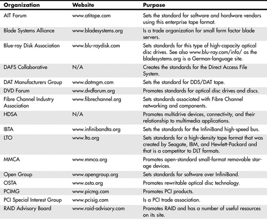
Table 12.1 lists some of the most prominent storage industry trade associations and standards committees. Their websites are great places to learn about current and future storage and server networking technologies.
Table 12.1 Storage and Server Trade Industry Organizations and Associations

To discuss SANs intelligently and make some sense about what standards are really important, we need a framework to place the various storage networking components in context. In an effort to bring all kinds of storage technologies into a unified theoretical framework, SNIA has developed a storage networking model that is similar in approach to the seven-layer ISO/OSI networking model. Figure 12.3 shows the SNIA shared-storage networking architectural model, which was created by Wayne Rickard, John Wilkes, David Black, and Harald Skadal, along with input from other members of SNIA during a period from 2000 to 2003.
Figure 12.3 The SNIA shared storage networking architectural model provides a context in which to discuss various networking devices and standards. Used by permission of SNIA (www.snia.org).

The SNIA storage model defines a set of architectural layers, functions, and services that are used to network storage. These layers define a set of interfaces: Some of those interfaces are contained within the storage devices themselves, some are conceptual interfaces, and some are actual network interfaces. By using this model, it is possible to describe where services are necessary, pinpoint areas where interoperability is a problem (typically at common interfaces), and describe the advantages and disadvantages of any particular storage networking approach. The SNIA model gives us a vocabulary we can use to compare different approaches and a framework we can use to define hardware and software. We can't use this model to describe whether any particular architecture or product is better than any other—only that if you install a certain device, you will need certain other kinds of hardware and software to complete the solution.
In the SNIA model, the storage domain is the hardware container that stores your data. At the top of the container is organized information in the form of files or information stored in organized containers: fields and records with the associated metadata needed to make sense of what's stored in them. The file/record layer's function is to provide the means to access information and the logic necessary to package information for storage. The logic required involves taking small units of data and associating that data with a naming space allocation scheme in order to construct larger data structures. At the file/record level in the storage model is placed a data cache, which provides a means for data retrieval of commonly or recently used information. Caching data enhances a storage system's performance. Finally, this layer also requires the logic to determine whether the information has been correctly transmitted out of storage or back in—which is often called a system's coherency.
The bottom layer of the model shows how information is stored in a storage network. At the lowest level, storage takes the form of blocks that contain data. Blocks have no high-level informational content but are merely locations contained within storage devices, such as hard drives, solid-state devices, tape, or optical discs. Each of these devices must have a way of organizing the blocks it contains (that is, organized pointers to each block). Block aggregation, or block address mapping, allows you to organize information in blocks without regard to where the blocks are located.
The term aggregation is synonymous with the concept of virtualization, where the definition of information is abstracted from the actual physical storage. You saw a number of examples of aggregation in Chapter 11, in the form of RAID. Virtualization also includes the concept of logical units (LUNs) and volumes, and the software you use to manage them, called volume managers.
![]() See "Introduction to RAID," p. 600.
See "Introduction to RAID," p. 600.
Because you can attain a performance advantage by caching commonly or recently used blocks, caching is also part of the block layer. On-board cache is the reason that modern enterprise disks ship with 8MB of memory or more.
The third part of the SNIA storage model is the access paths that you see as arrow-headed lines leading from the application layer to the storage devices. Each of the eight possible paths that can be defined represents a different method of data storage and retrieval.
If you examine Figure 12.3 closely, you see that there are four defined networks or interfaces:
- Application/operating system—This interface is composed of an API that connects the two layers.
- Operating system/file layer—This interface also consists of an API.
- File layer/block layer—The file/block layer is the storage network layer.
- Block layer/storage device—Blocks and their device storage involve a bus interface such as PCI.
When you hear the word interface, you should picture a duck dropping from the ceiling and saying the two magic words: trouble and opportunity. Interfaces are troublesome (and make IT folk grouchy) because they are where most of the interoperability issues crop up. Interfaces also offer an opportunity because when they are open standards, they allow you to pick different devices above and below them, offer horizontal scaling opportunities, and provide a measure of supplier independence. Thus, if you have storage software written on an industry-standard API, any device that can talk to that API can connect to your SAN at that point in the topology. Thus, it is a widespread trend in the industry to openly publish central APIs, even when (as is the case with EMC, for example) the API is highly proprietary because it allows other vendors to write to that API and extend its value. An important consideration in building any SAN, regardless of the size, is to consider these four interfaces as fundamental building blocks and choose accordingly.
Components of a SAN
You've already seen the minimum components of a SAN: a storage device, a connection device, and physical wiring. You build a SAN because it offers you the flexibility to add many components to a network and turn them into a shared resource at a very high speed. Therefore, you can expect to see all manner of devices attached to a SAN, including the following:
- Application and file servers
- Simple disk arrays and intelligent disk arrays
- NAS (filers)
- Caching servers (such as Microsoft Internet Security and Acceleration Server [ISA])
- Solid-state caching devices
- Tape backup drives and tape libraries
- Optical disc jukeboxes
- Network traffic directors or routers
- Load-balancing appliances
- Distributed file system servers
- Data movers
- Hierarchical storage management (HSM) systems (near online storage)
Storage networking is one of the most dynamic areas of technology around, and many new devices and software products are introduced every year. All these devices can be related to the shared storage model we've been discussing. Let's use some of the vocabulary you've just seen to put some of the various storage networking devices into context.
Block-Oriented Servers
The block layer is where you manage data, create fault tolerance, and organize data for best performance. That means that the following devices are assigned as block-level devices:
- Host (servers) devices, including logical volume mangers and device driver software and HBAs
- The HBA of a specialized storage network appliance
- Storage devices, in the form of RAID or disk controllers
The system of I/O that is used to aggregate blocks passes a vector of block addresses between the file/record layer and the block layer. Thus, a typical block-layer device can span three layers of the model, as shown by the prototypical block-layer device, a disk array (refer to Figure 12.3).
In fact, block-oriented architectures don't even need to be fully contained within the block layer. As you can see in Figure 12.4, a host (or server) connected to a DAS device extends this type of SAN component to other layers, such as the three hosts shown spanning the file/record layer. Block-oriented devices require three components: disk storage, aggregation, and the logic necessary to supply data to applications.
Figure 12.4 Block-oriented devices require a three-layer approach to storage networking. This figure is used by permission of SNIA.

File-Oriented Servers
The file/record layer offers different opportunities for the creation of storage networked devices. What happens at the file/record layer is a mapping function of volumes to files and volumes to tables and tuples, which are essentially the functions of a file system. (This is a different kind of mapping than the block address mapping done in the block layer.)
A file system can be at the operating system level in a host, in a database server or its equivalent, or in a distributed file system, some of which are built around HTTP protocol caches.
SAN components that are file-oriented devices may be any of the following:
- Host-based devices—These include not only OS file systems and databases (such as Oracle Parallel Server), but NFS (Network File System) or CIFS (Common Internet File System) file servers and their clients as well. A SAMBA share is an example of one of these client/server systems, but the entire storage system actually must include the client portion as well.
- A storage networking appliance such as a NAS head—A NAS head is a server that includes all the logic of a NAS device but not the disk function.
- A fully configured file-oriented storage server—This is a NAS with an associated array.
Figure 12.5 shows how file-oriented storage devices are illustrated within the SNIA networking model.
Figure 12.5 File-oriented storage devices. Figure courtesy of SNIA.
Thus, you can see that even file-oriented storage devices can incorporate various layers in the SNIA model. A NAS server is essentially a SAN in a box; it spans all the layers, from the very lowest block level through the file/record layer that connects directly into the LAN. From a host's point of view, a NAS server appears on the network as any other host would. Similarly, a NAS head also appears as a named server on a network, but unlike a fully contained NAS server, a NAS head requires a connection to a storage network to a disk array to be a fully functional storage device. That is, you can't just plug a NAS head into an Ethernet switch and have it work as soon as you assign a TCP/IP address to it.
Host-oriented, file-based storage devices require not only an HBA to be functional but also a logical volume manager (LVM) to supply the mapping function. Depending on the type of disk controller used, the HBA can be a simple network interface to the storage network (the storage network–attached host on the right in Figure 12.5), or, when the host has either software or hardware RAID, the block mapping function can be moved into the file layer of the host.
At nearly any point in a SAN, it makes sense to place a cache. Referring again to Figure 12.5, which shows the various file-oriented servers, you could put a cache in each of the storage servers, with the exception of the host with LVM and the NAS head. The reason you wouldn't cache those two servers is that you get faster performance from caching the disk array that they both connect to. Caching is a very important application in SANs, and caching appliances are in fact their own category of devices. Network Appliances, for example, has a significant business in cache appliances that are specially tuned filers. From a topological viewpoint, you would place a cache appliance in the network block aggregation layer, directly into the storage network, where it's central location benefits all devices connected to the SAN.
All the aforementioned theoretical discussion brings up the essential point that there are two basic types of storage networking devices: block-oriented and file-oriented servers.
Intelligent disk arrays such as an EMS Symmetrix, an HDS Freedom, or a Hewlett-Packard StorageWorks server are block-oriented servers. The classic examples of NAS servers are Network Appliances's filers (FS series), EMC Celera, and Dell PowerVaults, to name but a few. There are the big boys, very large storage deployment devices, and there are much smaller departmental and personal storage devices that are similarly architected. Each offers a distributed storage solution, but the two different approaches are better at doing different things. A block-oriented server is highly efficient at moving volumes of data, such as backup or in transactional systems. A file-oriented server is best at serving up files, and it is particularly good at serving up big files, as you might have for streaming applications.
While this discussion is rather theoretical in nature, it is important because by simply keeping this one fundamental difference between storage server types in mind, it is possible to guess the reasons that different storage network devices or architectures and different software applications hold sway where they do.
Software and Services
A SAN has the same requirements for managing components as any other network does. Therefore, the SNIA model defines a services component that spans all layers of the storage domain. SAN software runs the gamut in size and cost. There's free Open Source software such as the Samba file-sharing software. You often find a lot of software bundled with the hardware you buy; it isn't exactly free, but it is of unknown cost. Software written for SANs—even common server software such as backup programs—tends to be expensive. The most capable packages (for example, SANPoint Control and Foundation) can costs hundreds of thousands of dollars to employ on a SAN.
But here's the thing about SAN software: It is absolutely the most critical part of a SAN and holds the greatest opportunity for both short-term and long-term success, as measured by both performance gains and cost savings. When considering building a SAN, after you decide exactly what functions you need to implement, your next consideration should be the software.
Refer to Figure 12.3, where the SNIA model shows software in the services layer. The following classifications of software would be included as service-layer applications:
- Discovery and monitoring software determines what assets are on the SAN at any moment.
- Resource management and configuration software measures the performance of a SAN's components and allows you to modify them.
- Security and billing applications allow you to secure components as well as bill for SAN usage.
- Redundancy applications include both backup and snapshot software. (Software RAID is considered to be part of the host's block aggregation function and not grouped in this category.)
- High-availability and fault-tolerant applications, such as clustering and failover, are also accommodated as part of the storage networking model. One of the reasons that people build SANs is to make their distributed storage assets highly available. By using software that allows for multinode LVM or a Cluster FS (File System) that is spread over two or more NAS heads (for example), you can perform load balancing and multipathing, features that create high availability and scalability.
- Capacity planning applications let you predict when you need to bring resources online or, better yet, tell you when you can take them offline.
Arrays
Arrays are the stars of the SAN world. That may be because it is in the storage container itself that the most money is spent. However, it is also because the arrays of today come with an unprecedented amount of intelligence, in the forms of built-in capabilities and special software for management and staging as well as many specialized tasks. It's easy to develop a storage-server-centric point of view.
When it comes to storage, people use the term arrays rather loosely. An array is a storage container that contains multiple storage devices that can be managed as a single entity from either a connected host or a remote point. Some arrays are small—a collection of disks you can count on your hand(s)—and live inside your application server. At the high end are storage servers the size of a very large refrigerator, such as the Symmetrix DMX3000, which can contain up to 584 disks and more than a terabyte of disk space. There's a clear distinction being made in the industry between a simple array and an "intelligent" array. An intelligent array implies a complete server solution.
Most often arrays are based on hard drives, and nearly all arrays support RAID. But solid-state memory caching servers are also configured as disk arrays, and large managed tape libraries are also referred to as tape arrays; a few even support what is called tape RAID. Any RAID configuration is by definition an array. Depending on your point of view, an enclosure set up as a JBOD may or may not be an array.
To qualify as an array, a storage system should be able to be managed by some form of control software. Control software presents a unified method for defining data structures, executing commands that are carried out in a disk controller or intelligent HBA, or executing logic in the BIOS of the storage server as part of the firmware. Nearly any array you purchase comes with software to manage that array. You can also buy software from third parties to manage various storage arrays.
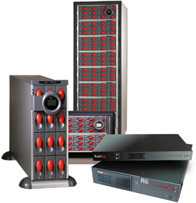
Raidtec's line of products exemplifies the range of devices to which the term array is applied. Raidtec (www.raidtec.com) sells an external DAS array called the Raidtec CS3102, which connects to a server using a dual Ultra 320 LVD SCSI controller. Because it is an entry-level system, the CS3102 is populated with SATA disks. Further up the food chain in Raidtec's DAS offerings is its FlexArray Ultra, which is an Ultra 160 SCSI host independent. Raidtec is known primarily for its smaller systems and has been acquired by Plasmon (www.plasmon.com). However, it also has larger products. Its FibreArray Extreme array with Fibre Channel connectivity is the large server in Figure 12.6. In this figure, there are 1u and 2u devices. Raidtec also sells a NAS box, the SNAZ Pro, a managed NAS server with an integrated Fibre Channel SAN router; the SNAZ Elite; and the large array shown in the figure, which is the FibreArray AA solution. Each of these storage systems qualifies as an array, but each is meant to be used with different applications.
Figure 12.6 The Raidtec family of products spans the range from small DAS arrays up to large enterprise arrays meant for SAN applications.
Raidtec is only an example of what is a very large marketplace of system manufacturers where no vendor really dominates the industry. Other vendors that offer arrays for the server market are listed in Table 12.2. Chances are that when you purchased your server, your server vendor had an array that it wanted you to buy. All server hardware companies either own or partner with companies that make arrays. Dell, for example, has the PowerVault line of products. In some instances, Dell's products are rebranded from vendors such as IBM or EMC, and in others, they are assembled at Dell. Hewlett-Packard and Sun have storage divisions that build storage arrays, and IBM's storage division (which was sold to Hitachi Data Systems) was another OEM. All these vendors offer a very large range of arrays, from small to large.
Table 12.2 Array and Storage Server Vendors


When considering an array, you need to consider the following properties:
- Capacity—You need to consider the number of disks and the type of disks supported.
- Connectivity—You need to consider the array's means to connect to either a host or the SAN.
- Fault tolerance—For an array, fault tolerance translates into the elimination of any single point of failure. The array should connect to a host or SAN using multiple connections (multipathing), be able to sustain HBA and disk failures, and so forth.
- Intelligence—You need to consider where onboard processors and HBAs do the I/O processing.
- Manageability—Manageability translates into the ability of the array to be managed in software either locally (at the array), at a switch, or at a host.
- Interoperability—Interoperability means that the array can exchange data with other devices on the SAN.
At the higher end of the food chain are a few vendors and some notable product lines. Most people would recognize the lines of the large block-oriented servers: EMC Symmetrix DMX, Hewlett-Packard StorageWorks XP, the Hitachi Data Systems Lightening 9900 or Thunder 9500, or IBM TotalStorage DS arrays. However, the term array applies equally well to NAS file servers, such as Network Appliances's FAS980 and EMC's Cellera line, which also contains an array of disks. Figure 12.7 shows a picture of the FAS980. If you take the faceplate off the FAS980, you find that the system is a multidisk RAID array (RAID 4) that contains both an onboard processor and controllers and HBAs. Essentially, the FAS is a fully fledged computer, albeit one that is optimized for file services, and the NetApp boxes come with their own small, proprietary, high-performance operating system. All the products mentioned in this paragraph fall under the category of intelligent disk arrays, and it is only whether they are file- or block-oriented that separates one from another.
Figure 12.7 The Network Appliances FAS980 is a storage array that is optimized for file services and is a computer or host in its own right.

In purchasing a disk array for your server, you need to be concerned with only a few compatibility issues. A disk array either works with your server and its operating system or it doesn't. In most cases, this compatibility has more to do with the disk or RAID controller than it does with the array hardware itself. As you move up to the very large storage arrays, their use of onboard processors and proprietary operating systems means that you need to be very concerned with their ability to interoperate with other hosts and storage systems. Many companies advertise what they call "open systems storage solutions," which may mean that their servers work with multiple types of hosts, or simply that their servers can connect to various flavors of UNIX.
Fibre Channel SANs
The HBA you use to connect a device to a storage network determines the physical connection type or medium as well as the transport protocol you use. In Chapter 11 we considered some of the most common HBAs—in particular, various forms of SCSI and Fibre Channel—and briefly described their utility in building SANs. Both SCSI and Fibre Channel are used to connect servers to DAS systems. The small number of possible nodes on a SCSI bus and the short-run lengths of that medium limit SCSI to only DAS storage. But Fibre Channel is another story.
![]() See "HBAs and RAID Controllers," p. 593.
See "HBAs and RAID Controllers," p. 593.
Fibre Channel is, for the moment at least, the dominant interconnect technology used to create SANs. Although Fibre Channel SANs were originally in the form of arbitrated loops, for the past several years Fibre Channel fabric SANs have dominated. A Fibre Channel bus can support 126 drives or nodes per bus, with a theoretical 40 to 60 nodes in practice, which limits a FC-AL to small storage networks and more often to the internal connections in large storage servers. When you attach a Fibre Channel HBA to a fabric switch, the fan out to other fabric switches allows for 224, or 16 million, nodes. Although Fibre Channel is still expensive and somewhat difficult to connect correctly, it still accounts for most of the sales in the SAN HBA market.
More About Fibre Channel
Fibre Channel is described as having two layers: a lower signaling level and an upper level of services and protocol mapping. The signaling layer includes the physical interface and media layer (FC-0) on which a transmission or wire protocol is layered (FC-1). Signals are frames that travel in a framing and signaling protocol layer that form the top of the signaling layer (FC-2). In the upper layer are common services (FC-3) on which there is a protocol mapping layer (FC-4), which is where the framing rules are applied. The FC-3 layer transports information about fabric network device discovery, RAID levels, the type of encryption and compression being used. The FC-4 layer allows for mapping bus protocols like SCSI, IP, and VI (virtual interface).
More important in determining compatible hardware is the Fibre Channel class levels. A Fibre Channel class determines the flow control in the FC-2 layer, and that is how Fibre Channel components negotiate with one another. You need to match device classes if you can to optimize performance. Currently, six classes are defined:
- Class 1—This class is used for end-to-end connections. Because each frame is verified, in Class 1 there is no negotiation; each device in the point-to-point connection has the full attention of the wire. Class 1 isn't used on any shared storage system because it is a closed system.
- Class 2—This class is a frame-switched connection that allows for a shared connection in a fabric. Although Class 2 verifies all frame delivery, it does not require that frames be ordered in any way. Because frames aren't sequential, Class 2 Fibre Channel can't be used for SCSI data, which must be sequential. Some vendors' Class 2 switches support sequential delivery as a proprietary feature. You can tell which switches those are because they support SCSI over Fibre Channel.
- Class 3—This class is another frame-switched connection, but here the overhead of frame acknowledgement is removed. It is up to the target and source systems to determine whether a transmission has been successfully accomplished. Class 3 uses the buffer-to-buffer flow control method that is described later in this section. Class 3 Fibre Channel also doesn't sequence frames, but it does include a broadcast feature that can send simultaneous traffic to more than one device.
- Class 4—This class allows for fractional bandwidth allocation on a fabric, using what is called a virtual circuit. Thus, Class 4 allows for a shared connection but offers some of the advantages of Class 1 Fibre Channel. Class 4 is just coming into use.
- Class 5—This class is a definition of isochronous (same time) and just-in-time service. It is unclear whether Class 5 will ever be implemented in products.
- Class 6—This class is a proposed multicast fabric service with dedicated connections.
Note
You can find a detailed tutorial on Fibre Channel standards at www.recoverdata.com/fc_tutorial.htm#Class%204.
The most common type of Fibre Channel in use today is the 100MBps variety. Earlier standards of 25MBps and 50MBps were used, and today they are referred to as quarter- and half-speed Fibre Channel. These slower speeds exist as part of legacy deployments. The road map for Fibre Channel includes 200MBps HBAs and switches (which are just starting to be employed), with 400MBps and 1GBps speeds promised. Given that competitive technologies are being introduced in the 1GBps range and above, it is likely that vendors will ignore 400MBps and jump directly to the 1GBps (and faster) speeds.
In Fibre Channel connections, cables and connectors are passive devices. The signal is transmitted and received by an electronic component called a transceiver. Each Fibre Channel connection contains two transceivers, and traffic down each wire flows in one direction. Thus one wire transmits data from one port to another port, while on the second wire connecting these two ports, data is transmitted in the opposite direction. Therefore, Fibre Channel avoids a number of issues that plague other networking technologies, such as Ethernet: signal contention and interference. A two-wire transmission scheme also simplifies the connectors so that they are easier to design and implement. The real advantage that Fibre Channel offers is that a loop or fabric network eliminates a single point of failure because most Fibre Channel HBAs used are dual homed, to take advantage of loop topology.
Switches
Although you can buy Fibre Channel hubs and routers, most Fibre Channel interconnect devices sold are switches. On SANs, switches can be small and unmanaged, but most often they are managed devices with some intelligence. A Fibre Channel SAN switch has the following:
- Onboard processing
- The capability to route storage traffic
- The capability to be both discoverable and manageable through SNMP
- The capability to be programmable through the vendor's API
Entry-level Fibre Channel switches go up to around 16 ports. Brocade (www.brocade.com) dominates the market for entry-level switches with its SilkWorm line. Brocade also does well in the larger workgroup switches space; these devices are most often defined as having 16 to 64 ports. Figure 12.8 shows the highly regarded 16-port SilkWorm 3850 fabric switch, which is a 2Gbps-per-port autosensing switch. This switch is compatible with the slower 1Gbps devices. Brocade's switches go up to the 4Gbps speed and to the higher end of the switch market—64 ports and beyond—where switches are referred to as director-class or director-level switches.
Figure 12.8 The Brocade SilkWorm 3850 16-port 2Gbps Fibre Channel switch.

Brocade is so well entrenched in this marketplace that its API has become something of a standard. Nearly all software management programs, autodiscovery software, and other SAN software offerings support Brocade's products.
Brocade does have competitors, and it is in the workgroup and director-class markets that there is vigorous competition. The company in the director class with the most market share is McData, with its Intrepid switches. Other significant players are Cisco, with its MDS line of switches, and QLogic. Cisco is the 800-pound gorilla of the networking market, but although the company was expected to become a major player in storage networking, it has moved slowly in this marketplace.
A simple FC-AL loop topology can be created by connected all devices to a nonswitching Fibre Channel router or hub. Connecting two FC-ALs together requires having a switched path, and the simplest way to create that is to connect a switching hub on one FC-AL through a Fibre Channel bridge to the second FC-AL. When you connect multiple loops, they share the address space but not the bandwidth: Each loop still has its full rated speed available to its connected devices.
A fabric topology requires (as you saw earlier in this chapter) at a minimum a switch into which all devices are connected. It's easier to build a fabric than a loop topology in that you can connect two switches to one another to grow your network.
Port Types
To understand how SAN connections are made, you need to know a little bit about switch port definition. Each connection on a Fibre Channel switch is called a port, and each connection on the Fibre Channel HBA is also called a port. Any Fibre Channel device that you hook up using a Fibre Channel cable to a Fibre Channel–based SAN—be it a hub, switch, bridge, or system—is a port on the storage network. The cable attaches to one port on one end and one port on the other end so that for each port there is a single cable connection. The entire system attached to a Fibre Channel HBA is referred to as a node.
Fibre Channel defines eight port types:
- B-ports are bridging ports that can connect to additional networks.
- N-ports are used in fabric switches where they both initiate and receive frames.
- L-ports are used in loops.
- NL-ports can be used for both fabrics and loops, and they can be used to connect through a loop to a fabric.
- E-ports are switch ports that connect to other switch ports.
- F-ports are switch ports that connect to N-ports.
- FL-ports are switch ports that connect to NL-ports.
- G-ports are common, or "generic," ports that can be used to connect to E, F, or FL-ports.
All Fibre Channel ports and connections are passive; all the addressing and packaging of frames is done in the controller. Fibre Channel provides a heartbeat so that regular signals are sent between N-ports and F-ports and are received to indicate the port status. Because L-ports were designed to work in loops, they both initiate and control traffic.
Addressing
Fibre Channel has its own addressing and naming scheme, just like Ethernet does. To create a unique network name, Fibre Channel uses the following:
- World Wide Name (WWN)—The WWN is a 64-bit identification number that is assigned for each Fibre Channel device by the manufacturer and burned into the device's ROM. You can think of the WWN as Fibre Channel's equivalent of an Ethernet MAC address; when you discover a Fibre Channel port in software, you can inventory what's attached to it using the WWN.
- Port address—A port address is a unique 24-bit address that is assigned to a port on a network. You can think of a port address as the Fibre Channel equivalent of an IP address in a TCP/IP network. The 24-bit address space defines 224, or 16 million (16,777,216), possible addresses. Assignment of port address numbers is determined by the person or organization setting up a Fibre Channel SAN.
- Arbitrated Loop Physical Address (AL-PA)—AL-PA is used on loop topologies to define an addressable and unique address. Because loops have a much lower number of connected nodes, an 8-bit address scheme allowing 256 possible addresses, which is the theoretical limit.
Traffic Flow
To mitigate traffic over the network, Fibre Channel manages traffic by using a scheme called buffer credits. Each port is given a certain budget of traffic, and when that budget is used up, traffic is switched to the next port. Buffer credits are issued for end-to-end flow control where the destination N-port, L-port, or NL-port sends an acknowledgement that the frame arrived correctly and an additional credit is given to that port because it is now waiting for data. A second form of flow control, called buffer-to-buffer, manages a set of credits between adjacent ports. In this form of traffic control, the target port issues a receive ready signal to the sending port.
On a pure FC-AL network, all ports are L type, and this type of loop is called a private loop. No other network can access a private loop because it is a closed system. Many FC-ALs are built so that some devices can remain private while other devices are viewable to a connecting network. This sort of loop is called a public loop, as shown in Figure 12.9. On a public loop, private devices are still connected to L-ports, public devices are connected through NL-ports, and the arbitrated loop connects to another network via an FL-port connection to a switch.
Figure 12.9 A public loop.
For a Fibre Channel loop, the arbitration scheme used is similar to the one that SCSI uses to perform bus arbitration. In this scheme, the port with the highest priority gets priority to send and receive frames. Unlike SCSI, which determines priority based on electronics, on an FC-AL, the priority is done in the command language. As an L- or NL-port on an FC-AL requires loop access, it starts to issue commands that indicate it is ready. As the commands circulate the loop, each node determines its priority in relationship to the node requesting loop control; either that node takes command or passes the control command on.
At some point, the loop becomes available to the arbitrating port, traffic flows or an exchange occurs, and then another higher-priority node assumes command of the loop. Exchanges are a set of data sequences, where the data is sent as a frame and in a prescribed order (thus a sequence). Fibre Channel SANs use a rather small frame size, typically 2KB.
A Fibre Channel frame is similar in construction to other packet frame type networking protocols—that is, the frame has start and end markers, a header that defines the frame, addresses, data, error connection, and a validation data set that performs both acknowledgement and data recovery. A frame is constructed like an envelope. It encapsulates data, just like in other wire protocols, so that Fibre Channel can be constructed so that it maps to other upper-level protocols, such as SCSI, IP, HIPI, FICON, ESCON, 802.2, and Virtual Interface Architecture (VIA).
With a Fibre Channel fabric, a different kind of process is used to determine flow control. A set of nodes and process logons communicate the status of different port types in a fabric network. As each node logs on to the network, initiator and target ports perform a node logon, which establishes the data transfer connection. When different node types exist, the option process login can be used to establish the type of protocol that the transferred data uses. Fabric networks use the FCP (Fibre Channel Protocol) serial SCSI protocol. This kind of process happens for any type of Fibre Channel connections, even direct attached Fibre Channel.
Fibre Channel is almost always installed as a switched fabric for networked storage. However, that doesn't mean that Fibre Channel loops are going to disappear anytime soon. Internal Fibre Channel connections within storage devices such as large storage arrays will continue to be used for the foreseeable future.
TCP/IP Storage Networking
The advantages of TCP/IP storage networks is not only that you can use them to create a unified network but that the infrastructure and trained IT staff are more widely available and that Ethernet adapters, switches, and other hardware offer a great economy of scale—that is, components tend to either be less expensive to start out with or will become so over time.
Storage networking over IP is leveraging the investment that the industry has made in Ethernet. File-oriented storage traffic already travels over IP networks; that's what NAS or filers are designed to do. But these new standards hope that all kinds of storage traffic, even block-oriented, DAS, or Fibre Channel SAN data will function over IP networks. Doing so will expose storage traffic to a whole host of IP-based applications (backup, replication, and so forth) while allowing IP management tools and staff trained in IP methods to manage storage assets more easily.
Ethernet networks have always been used to send and receive storage data. Put aside the fact that NAS filers (NFS and CIFS) are often connected directly to a TCP/IP network, servers and clients are where very important data resides on DAS, and that means that backup traffic must flow from these systems. These historical uses of storage over Ethernet have been largely file based and have not been used to access block-oriented devices. The more recent developments, therefore, have been aimed at making storage traffic over TCP/IP a much more general phenomenon. It is expected that some of the technologies discussed in the next sections will have significant impact in the storage networking marketplace and will to some extent replace Fibre Channel SANs.
There are three approaches to sending storage traffic over IP networks:
- Fibre Channel over IP (FCIP)—FCIP uses tunneling to encapsulate Fibre Channel frames within IP packets, sends them over the IP network, and strips the encapsulation off when the packets arrive to restore the Fibre Channel frames. This is a point-to-point technology that has been compared to data transmission across a dedicated dark fibre link, where the initiator and target both have the overhead of encapsulation and removing the encapsulation.
- iSCSI—With iSCSI, a SCSI command and data are added to the IP protocol and then sent over the IP network. The processing is done on IP packets at the HBA, so one iSCSI HBA communicates with another. IP enhances SCSI by allowing the data and commands to be sent over a much greater distance, turning DAS into a networked storage asset.
- iFCP—Similar to iSCSI, iFCP adds Fibre Channel commands and data to IP packets and then sends the storage traffic as native transport. iFCP uses the Layer 4 Fibre Channel protocol as part of an IP packet, where the transmission of the IP packets is from iFCP gateway to iFCP gateway. Here, the IP infrastructure replaces the Fibre Channel fabric.
FCIP
Fibre Channel, while both scalable and reliable, imposes considerable cost. In addition, a significant amount of overhead is required to map Fibre Channel protocols so that they are compatible with their wrapper, and it is easy to transmit and translate the data when it arrives. When you exceed the distance that Fibre Channel can run (about 1.8km), storage traffic sent over long distances requires a different transport medium, and Fibre Channel is impractical.
What you really want to do is leverage the availability of established IP networks to send Fibre Channel data. Therefore, the industry is developing new standards that allow for WAN transmission of Fibre Channel as well as allow Fibre Channel traffic to use IP LANs when Fibre Channel SANs do not exist. These FCIP technologies are also regarded as a means of solving the problem of connecting "SAN islands"—that is, bridging two separate SANs by using FCIP gateways, whether they are located on different floors in a building, different buildings on a campus, or across the country.
Fibre Channel and IP networking have two very different design principles. Fibre Channel was designed to be fast and highly reliable. IP networks were designed to be fault tolerant but not necessarily fast. That Quality of Service (QoS) difference greatly affects how you can use FCIP technologies. FCIP exposes this difference, especially IP's intrinsic latency.
Many Fibre Channel SANs support high-speed transactional database systems. A transactional system like that can sustain a wait period of a second or so to retrieve some data in order to continue processing, but longer wait periods bring the transactional processing to a halt. When you send FCIP data across the room, there is perhaps one "hop": the latency involved with the path through the switch and the delay in its retransmission. Add a couple more hops to cross a city, and it's unlikely that FCIP is going to connect an OLTP database to primary storage.
Some processes tolerate latency. Backup is one example of where FCIP could be used. In a backup process, data is transmitted from one site to another. If there is latency, the data throughput is simply slower. How much slower? At current speeds, data over an OC-3 IP connection takes about six times as long as over a Fibre Channel SAN.
iFCP replaces the Fibre Channel transport layer with the TCP/IP protocol set and GigE wire transport. It does not create native IP packets, but it does allow for fast point-to-point dedicated connections between two iFCP gateways or switches. The iFCP gateways communicate with Fibre Channel devices and make the necessary conversion. The main market for iFCP deployment is enterprise-class backup, replication, and storage virtualization.
iSCSI
The iSCSI protocol defines a set of rules that determine how to send and receive SCSI-3 commands along with the block storage data on SCSI attached storage over TCP/IP. Because what is being communicated is IP packets, you can send iSCSI over GigE. iSCSI is placed just above the data link layer in the OSI networking model, and it directly interacts with a host's SCSI access method command set. Although any TCP/IP transport is generally defined to work over any TCP/IP network and can even be implemented entirely in software, almost all implementations of iSCSI use a specially constructed HBA that interfaces with GigE.
Not only can iSCSI connect two different IP SANs, it is also possible to use an iSCSI-FC gateway to provide access to storage on a Fibre Channel SAN. Thus iSCSI can link storage over not only LAN but MAN and WAN networks. However, the first iSCSI HBAs from companies such as Adaptec are aimed at getting SCSI storage that is DAS to be made available to other systems in small workgroup or departmental settings. We haven't yet seen enterprise iSCSI devices appear, but the HBAs that should enable this technology started appearing in the market in 2003.
SAN Backup
Any serious storage networking professional knows that backup is the "killer app" of storage networking. Backup is the one application that every SAN runs, and it is considered to be either the most mission-critical application for the organization or nearly so. Many SANs exist solely for the purpose of backup and recovery. And while it's an axiom that no one ever gets promoted for doing a great job on backups, it's also true that the life expectancy of an administrator who can't restore critical data from backups can be clocked with an egg timer.
Backup over a SAN adds significant convenience and additional capability to the task at hand that isn't there when you back up either locally or over a network. With centralized SAN backup hardware and software, you get an economy of scale that you don't have with smaller forms of backup. But the most important reason that backup is such a powerful selling point for SANs is that it removes one of the primary consumers of network bandwidth from your corporate LAN. With SAN backup, you don't have to wait for periods of inactivity to perform a backup, and you can make better use of the backup resources that you do have.
Up until a few years ago, the predominant form of SAN backup was to tape. Tape is a relatively inexpensive storage medium, and tape technologies have steadily improved in performance and capacity over the years. However, the cost and capacity of disk storage have improved even more significantly than those of tape, leading to a situation where the cost of disk capacity is now similar to the cost for the same capacity of tape storage.
Each of these two media offers different capabilities that complement each other. Tape is portable and reliable, but it affords only serial access to data, and it is mind-numbingly slow. Hard disks are faster and offer parallel access to stored data, but they're not portable. Consequently, disk backup is used more often on SANs for first-level backup and snapshots, where the most recent data is stored. Tape has taken the role of near-online backup and archival storage. Taken together, server, disk, and tape offer a multilayered approach to backup that is both flexible and prudent.
Note
You can find a detailed discussion comparing tape to disk backup on UltraBac's website, at www.ultrabac.com/techsupport/50white-papers/UBS_tapevsdisk.asp.
Tape Formats and Libraries
Tape drives have a long and storied past. Space precludes a historical presentation here, but the reality of the current situation is that there are really only three tape formats that are in common use in server/SAN deployments:
- DLT (Digital Linear Tape) format—For years, Quantum's DLT was the enterprise tape format of choice. The format originated from technology developed at DEC, and it has the broadest industry support, including Dell, Hewlett-Packard, Maxell, Fujifilm, Exabyte, and many others. The DLT IV version offers a 40GB native tape capacity and a native transfer rate of 3MBps–6MBps. It has been estimated that DLT (as well as SDLT) has a 30-year life span and can sustain one million read/writes.
SDLT (Super DLT) is a higher-capacity and higher-speed version of the DLT format. The current version is SDLT-320. The road map for Super DLT goes up to DLT VS600 tapes of 600GB. - LTO (Linear Tape Open) format—This format is a joint offering from Hewlett-Packard, IBM, and Seagate, and it is a competitor for SDLT. Several generations of LTO are planned, but the first has tapes with a native capacity of 100GB uncompressed and up to 200GB compressed.
Ultrium is one of the two formats of LTO. There are two versions of Ultrium, Ultrium-1 and Ultrium-2, the latter of which has a 200GB native format and a fast transfer rate of 30MBps. Ultrium-2 puts a small 4KB memory chip onto the tape cartridge, into which is stored the directory of records written on the tape. That directory allows the tape to go to the record on the tape when required without having to first rewind to the directory on the tape for the location. - AIT format—Two versions of this backup format, developed at Sony, exist: AIT-2 and AIT-3. AIT-2 offers tapes of 50GB uncompressed and about two to three times that compressed, with a 6MBps transfer rate. The AIT-2 format is a competitor for DLT, and it isn't a contemporary choice for servers. AIT-2's replacement, AIT-3, offers 100GB native capacity, with a 12MBps transfer rate.
Of course, there are many other tape formats, including VXA, ADR, SLR, Mammoth, Travan, and Accelis, but these are older DAS tape formats. Of the formats mentioned previously, SDLT and LTO are the two that are still deployed on SANs. What makes these two formats the ones of choice is not only that they have high capacities and transfer rates but that the casing for these tape formats was specially ruggedized to withstand the wear and tear of handling in robotic tape libraries. Typically, SDLT-320 drives use Ultra SCSI connections, whereas Ultrium-2 drives are found in both Ultra SCSI and Fibre Channel connections.
The most important tape backup system is the robotic multitape carousel or library. Because modern enterprise tape cartridges duplicate approximately one single hard drive (roughly speaking), tape backup must use a significant number of tapes in order to create archival copies. When snapshots are stored, an even larger capacity is required. Let's consider some representative examples of enterprise tape storage system.
At the low end for SAN tape systems are autoloaders such as the $5,000 Exabyte Magnum 1X7 LTO-2 2u tape system shown in Figure 12.10. A carousel of seven 200GB LTO-2 tapes are passed around a circle and are read/written to by a single tape drive at the back of the unit. The capacity of the system is 1.4TB native and 2.8 compressed, with a throughput of 169MBps, using the two Ultra 320 SCSI ports. Systems of this type can be rack mounted. Exabyte is one of the larger tape system vendors, and it offers a variety of tape systems and formats. The LTO series moves up to more tape heads and more tapes. Exabyte systems come with software that lets you manage them remotely.
Figure 12.10 The Exabyte LTO-2 Magnum 1X7 autoloader.

Note
When purchasing or intending to use a tape system, make sure that your backup software contains an up-to-date driver for that system.
The next step up from an autoloader is a tape library. Tape libraries look like the kinds of automation you see in science fiction and spy movies. They come in sizes ranging from a desktop model to the more commonly seen size of a file cabinet or refrigerator up to absolutely mammoth systems that fill enormous rooms. One system, built by eMASS (now a part of ADIC) for the Internal Revenue Service, fills an entire building.
Because the only way to make certain that a unit functions correctly is to see the robotics in action, tape libraries often come with see-through doors. Unlike an autoloader, a library comes with multiple tape drives, often not of the same type. Having multiple tape drives operating at the same time enables fantastic throughputs, features such as tape RAID, internal tape calibration, redundant systems, and very broad heterogeneous networking support. Pricing is almost never standard, and it is quoted on a per-system build, depending on the components.
As an example of a tape library, consider the StorageTek 9740 shown in Figure 12.11. This system can contain up to 494 cartridges, 10 tape drives, and 6 slots with a capacity of up to 30TB uncompressed tape when fully populated by DLT, or 60TB compressed. Tape libraries are often expandable, with an extra cabinet added to the side of the starter and with the robotics used to service the combined unit. Companies buy these tape libraries to back up the enterprise-class storage servers described earlier in this chapter. To give this some scale, you could back up roughly 15 EMC Symmetrix DMX servers like the one you saw earlier in this chapter. Companies buy tape libraries to help them archive, do backup and restoration, and to be the last line of defense in a disaster recovery system.
Figure 12.11 The StorageTek Timberwolf 9740 enterprise-class tape library.

Disk Backup Hardware
There are a lot of good reasons people back up their SAN data to disk systems. (Chapter 11 describes some disk backup systems, although it doesn't stress backup.) People use storage arrays and storage servers to back each other up. Internally, arrays can be backed up in hardware RAID, using mirroring and replication techniques. BCV (Business Continuance Volume) is just a fancy way of saying disk-to-disk backup. Disk-based backup is more reliable, more fault-tolerant, and a great deal faster than tape.
Of course, some vendors offer storage arrays that are specially outfitted for disk-to-disk backup. For example, consider the DX series from Quantum (see www.quantum.com/am/products/eb/default.htm). The DX30 array offers 277MBps throughput to up to 16TB of disk. Its bigger brother, the DX100, stores 64TB of disk. Organizations invest in disk-to-disk storage devices because they solve some thorny backup problems. With tape, you are always fighting to keep backups within a reasonable backup window. You can throw more and more tape hardware at the problem, but because tape is so much slower than disk, it's a much more expensive proposition. Using disk arrays to back up your email or large databases lets you restore a system much more quickly while still giving you the opportunity to do versioning using snapshots.
SAN Backup Software and Servers
When you prepare to back up a server over a SAN, typically your server is one of a pool of systems. If your server is to be backed up, it is a matter of adding your server to the backup routine and defining the parameters of the backup. The parameters might include which disk(s) to back up, how often, and using what method (full backup, incremental backup, snapshot, and so on). Some programs let you access the backup program remotely and set up the backup, or you can pop a terminal session and log in to the system. There's nothing substantially different about setting up a system to be backed up over a SAN; the software you use is similar to what you might have used in the past to do local backup. Enterprise backup software has a number of features that are unique, as described later in this chapter.
Much of the real action in SAN backups becomes apparent when your server is one of the "backupers." Backup servers on a SAN run enterprise backup software, and you need to consider a number of factors to get them to perform effectively. Here's a fact for you to ponder: Typically 15% of all servers deployed in an enterprise are deployed as backup servers. Thus for small workgroups or departments, a backup server might be a lone wolf, but more often SAN-level backup requires multiple servers operating cooperatively when backing up other systems. When you select your backup software, you need to look for features such as master backup systems, backup groups, storage groups, backup policy and scripting, and other automation features that make it possible for as few IT staff to run the system as possible. Of course, you also need to look for wide device support within the software package because you never know what you might be called to back up from or to.
The major backup software packages in the SAN marketplace are VERITAS NetBackup, Computer Associates ARCserve, Legato Systems Networker, and Tivoli Systems Storage Manager. However, this is a crowded category with many more players. Smaller vendors such as BakBone, NovaNET, Syncsort, and others all have products in this area. Figure 12.12 shows you the main console from VERITAS's NetBackup software.
Figure 12.12 VERITAS NetBackup is a market leader in SAN backup software. Shown here is its main console.

You are probably familiar with centralized backup systems, but SANs enable some very interesting backup options, including the following:
- LAN free backup—In this type of setup, a host (server) communicates with storage on the SAN, and all backup traffic flows over the Fibre Channel SAN network. This method of backup is one of the main motivators for creating SANs because it eliminates one of the primary consumers of LAN bandwidth.
- Server free backup—You may not be familiar with server-free backups, but that's the next step in SAN backup design. In a server-free backup, the host commands a storage server to initiate a backup and gives it the parameters needed to perform the operation. Data from the source storage system is then moved by a data mover application to the backup system, using Extended Copy commands and data mapping operations. That is, backup is done on a block-level basis, and the snapshot image (also called a point-in-time backup) is performed, and the data is mapped to physical locations on the target system. Server-free backup requires even less host processing than LAN-free backup, and it is extremely efficient. However, it must be supported by the storage servers involved, and its command set must be supported in the HBA. Consequently, server-free backup is a work in progress and requires careful hardware/software selection to implement.
You need to consider two other concepts when it comes to backup software over a SAN: hot versus cold backup and vaulting. In a cold backup, you can close the running applications on a server and perform a complete backup, knowing that none of the data will change during the time of your backup or snapshot.
Many application servers that run over a SAN are either mission critical or do not have sufficient free time to enable a backup window to be established. You can't just shut down a corporate email server or a large transactional database. In such a situation, you need to perform a "warm" or "hot" backup. In a warm backup, special software designed for the enterprise application you need to back up quiesces the application so that it is running slowly and performs the backup. A hot backup backs up while the application is running, without slowing down any of the processing. A hot backup picks a point in time, runs the backup, and then examines a transaction log to see what transactions need to be backed up in order to bring the backup successfully to completion. Hot backup software is specific for the application it is backing up—an Oracle database or Exchange Server, for example—and can be quite expensive to implement.
Hot backups lead naturally to the concept of data vaulting. Data vaulting is a backup method that is done remotely so that the data is both duplicated and protected. The transmission is compressed, encrypted, and assembled. You can purchase data vaulting software, or you can buy it as a subscription service. Companies such as LiveVault and CommVault offer special techniques for backing up enterprise applications. The advantage of a vaulting application is that if all else fails, your friendly vaulting application is there to back you up. Vaulting should be viewed in the context of disaster recovery and applied to mission-critical systems and data.
Final Thoughts
In nearly all cases, people who operate servers don't usually install or maintain a SAN. The skill sets for the two tasks are very different. You are likely to need to call in a storage professional or an outside consulting firm to install a SAN. You may, however, need to connect a system or component to an existing SAN, which requires that you have some familiarity with Fibre Channel connection types and a basic understanding of device addressing and how to troubleshoot addressing problems.
Storage management on SANs is a big topic, and because it is storage-centric, we don't describe it fully here. However, as SANs become more widely adopted, and particularly as the components get cheaper, you may find that you are called upon to manage a SAN using specialized software. SAN management software offers autodiscovery technology, topology mapping, device properties drilldown, path analysis, and visualization that makes the job of managing a SAN easier. Some of these software packages are really software suites, bundling in volume managers, backup software, and other capabilities. You'll also find that the major network frameworks, such as Hewlett-Packard's OpenView, IBM's Tivoli, and CA's Unicenter TNG, all offer storage networking, backup, and other applications for managing SANs. Thus if you find yourself involved in working with SANs, you should investigate the capabilities of software in this area.