Chapter 4
Server Motherboards and BIOS
Without a doubt, the most important component in a PC server is the main board or motherboard. Some companies refer to the motherboard as a system board or planar. (The terms motherboard, main board, system board, and planar are interchangeable.) This chapter examines the various types of motherboards available for servers and those components typically contained on the motherboard and motherboard interface connectors.
Motherboard Types and Form Factors
Several common form factors are used for server motherboards. The form factor refers to the physical dimensions (size and shape) as well as certain connector, screw holes, and other positions that dictate into which type of case the board will fit. Some are true standards (meaning that all boards with that form factor are interchangeable), whereas others are not standardized enough to allow for interchangeability. Unfortunately, these nonstandard form factors preclude any easy upgrade or inexpensive replacement, which generally means they should be avoided. The most commonly known obsolete motherboard form factors used for servers include the following:
- Baby-AT
- Full-size AT
- WTX
The most commonly known current and emerging motherboard form factors used for servers include the following, listed according to form factor type:
Small form factor:
- SSI TEB (Thin Electronics Bay)
- microATX (AT Extended)
- microBTX (Balanced Technology Extended)
Tower and pedestal:
- microATX
- microBTX
- ATX
- Extended ATX
- BTX
- SSI CEB (Compact Electronics Bay)
- SSI EEB (Entry-Level Electronics Bay)
- SSI MEB (Midrange Electronics Bay)
- Proprietary designs (large x86-based; Itanium and RISC-based designs)
Rack-mounted:
- PICMG (PCI Industrial Computer Manufacturers Group)
- SSI CEB
- SSI TEB
- Blade servers
Note that some form factors fall into more than one category.
Before 1996, low-cost servers that used industry-standard form factors typically used motherboards based on the Baby-AT form factor, a reduced-size version of the AT motherboard used in the IBM AT PC introduced in 1984. Starting in 1996, standards-based server motherboards began to use the ATX form factor, the larger extended ATX, or, in rare instances, the reduced-size microATX design. Starting in 2005, servers based on the BTX form factor were introduced. BTX is an evolutionary development of ATX that provides for better thermal management of high-performance systems.
Although ATX and extended ATX are the most common server platforms for low-cost entry-level servers, starting in the late 1990s, Intel, in cooperation with Dell, IBM, and Silicon Graphics (SGI), developed a series of form factors especially designed for servers. These form factors are known collectively as Server System Infrastructure (SSI), and they support small form factor, pedestal, and rack-mounted servers. SSI form factors are used widely in entry-level servers based on x86 processors.
Other server form factors considered in this chapter include the PICMG family of standards, which are used primarily in specialized industries such as telecommunications, blade servers, and various proprietary designs used for high-capacity rack-mounted and pedestal servers. Although there are no de facto or official standards for blade servers, blade server designs represent a significant development in server architecture.
Some server form factors developed since the replacement of Baby-AT by newer designs have already been superseded. The SSI MEB form factor was designed to support up to four-way slot-mounted processors such as the Pentium III Xeon. With the development of more compact socketed processors, most vendors no longer use SSI MEB in its original form. Although some vendors use motherboards that have the same dimensions as SSI MEB, the motherboards are now designed for up to eight-way socketed server processors, such as the AMD Opteron. WTX was designed for workstations and medium-duty servers but never became popular. WTX motherboards today actually fit in Extended ATX cases.
Because most x86-based servers on the market today use one of the industry-standard form factors listed in this section, you can upgrade such servers by replacing the motherboard. You can replace an ATX motherboard with a more advanced ATX motherboard, an SSI EEB motherboard with a more advanced SSI EEB motherboard, and so forth. As long as the chassis and power supply provide the necessary thermal and power requirements for the new processors and memory installed on the new motherboard, you can create a like-new server as an alternative to purchasing a brand-new server platform. If you are building your own server, you need to make sure you use an industry-standard form factor. (Each of these form factors is discussed in more detail in the following sections.)
Form factors affect how much internal hardware a server can contain, and, in some cases, whether or how easily a server can be rack-mounted. Generally, servers based on SSI, PICMG, or blade server form factors are designed for or can be converted to rack-mounted form factors.
Tip
If you are planning to switch from a pedestal to a rack-mounted server in the next 24 months or less, purchase a pedestal server that can be converted to a rack-mounted server. Many vendors make pedestal servers or chassis that also support rack-mounting.
Anything that does not fit into one of the industry-standard form factors should be considered proprietary. Although it is possible to build up to an eight-way server by using off-the-shelf server components, the reality is that many four-way and larger servers are proprietary. If you need an eight-way or larger server, you should evaluate the vendor-provided upgrade paths available if you plan to use the server long enough to need a new generation of memory or processor options. Also, you should determine how spare parts are provided. Can you obtain them from more than one source, or must you use the vendor's own service department? These considerations will help you find the best fit in terms of serviceability and long life for a server you cannot upgrade with standard components.
ATX Motherboards
Although some vendors built servers based on the original IBM XT and AT motherboard form factors (AT and Baby-AT) from the 1980s through the mid-1990s, all servers using these form factors are long obsolete, and most of them have been replaced. Thus, the first form factor we consider in detail is the ATX form factor.
Intel initially released the official ATX specification in July 1995. It was written as an open specification for the industry. ATX boards didn't hit the market in force until mid-1996, when they rapidly began replacing Baby-AT boards in new systems. The ATX specification was updated to version 2.01 in February 1997, 2.03 in May 2000, 2.1 in June 2002, and 2.2 in February 2004. Intel publishes these detailed specifications so other manufacturers can use the interchangeable ATX design in their systems. The current specifications for ATX and other current motherboard types are available online from the Desktop Form Factors site: www.formfactors.org. ATX is the most popular motherboard form factor for new entry-level and midrange servers through at least 2006. An ATX system will be upgradable for many years to come, exactly as Baby-AT was in the past.
Note
Although many major server OEMs build machines that appear to meet the ATX form factor specifications, they may use proprietary cases or power supply designs to limit your upgrade options. If you want maximum flexibility, consider building your own server, based on ATX or SSI form factors.
The major features of an ATX motherboard include the following:
- Built-in double high external I/O connector panel—The rear portion of the motherboard includes a stacked I/O connector area that is 6.25 inches wide by 1.75 inches tall. This enables external connectors to be located directly on the board and negates the need for cables running from internal connectors to the back of the case as with Baby-AT designs.
- Single main keyed internal power supply connector—Most versions of ATX use a keyed 20-pin connector. However, some recent systems now use a 24-pin version of this connector. (Some high-end power supplies can be used with either motherboard connection.) Some systems use additional connectors.
![]() See "Power Supplies and Connectors," p. 247.
See "Power Supplies and Connectors," p. 247.
- Relocated CPU and memory (compared to Baby AT)—The CPU and memory are located next to the power supply, which is where the primary system fan is located. There is room for a CPU and a heatsink and fan combination of up to 2.8 inches in height, as well as more than adequate side clearance provided in that area.
Virtually any server today requires more cooling than the fan in the power supply can provide. This could come in the form of a secondary case-mounted fan or an active heatsink on the processor with an integral fan.
Intel and AMD supply processors with attached high-quality (ball bearing) fans for CPUs sold to smaller vendors. These are so-called boxed processors because they are sold in single-unit box quantities instead of cases of 100 or more, like the raw CPUs sold to the larger vendors. Boxed CPUs include active heatsinks to ensure proper cooling. They are the best choice if you are building your own server because of the long warranty coverage and because the active heatsink helps ensure proper cooling.
When they put high-quality fans on these boxed processors, Intel and AMD can put a warranty on the boxed processors that is independent of the system warranty. Larger vendors have the engineering talent to select the proper passive heatsink, thus reducing the cost of the system as well as increasing reliability. With an OEM non-boxed processor, the warranty is with the system vendor and not the processor manufacturer directly.
Heatsink mounting instructions are usually included with a motherboard if non-boxed processors are used. Servers that use proprietary processor cards or cartridges might combine a passive heatsink with a high-performance fan and duct system for cooling.
- Relocated internal I/O connectors—The internal I/O connectors for the floppy and hard disk drives are relocated to be near the drive bays and out from under the expansion board slot and drive bay areas. Therefore, internal cables to the drives can be much shorter, and accessing the connectors does not require card or drive removal.
- Improved cooling—The CPU and main memory are designed and positioned to improve overall system cooling. However, most servers require additional cooling fans for the CPU and chassis. Note that the ATX specification originally specified that the ATX power supply fan blows into the system chassis instead of outward. This reverse flow, or positive pressure design, pressurizes the case and minimizes dust and dirt intrusion. Later, the ATX specification was revised to allow the more normal standard flow, which negatively pressurizes the case by having the fan blow outward. Because the specification technically allows either type of airflow, and because some overall cooling efficiency is lost with the reverse flow design, most power supply manufacturers provide ATX power supplies with fans that exhaust air from the system, otherwise called a negative pressure design. See Chapter 15, "Chassis," for more detailed information.
Figure 4.1 shows the ATX system layout and chassis features of a typical entry-level server, as you would see them looking sideways in a tower with the side panel removed. Notice how virtually the entire motherboard is clear of the drive bays and how the devices such as CPU, memory, and internal drive connectors are easy to access and do not interfere with the bus slots. Also notice how the processor is positioned near the power supply.
Figure 4.1 When mounted inside the case, the ATX motherboard is oriented so that the CPU socket is near the power supply fan and case fan (if the case includes one).
The ATX motherboard shape is basically a Baby-AT design rotated sideways 90°. Compared to a Baby-AT design, the expansion slots are now parallel to the shorter side dimension and do not interfere with the CPU, memory, or I/O connector sockets (see Figure 4.2). There are actually two basic sizes used by ATX-based servers:
- A full-size ATX board is 12 inches wide by 9.6 inches deep (305mm244mm). See Figure 4.2.
- An Extended ATX board is 12 inches wide by 13.05 inches deep (305mm332mm).
Figure 4.2 ATX specification 2.2 motherboard dimensions.
MiniATX was once an official specification, but starting with ATX 2.1, it was dropped. Extended ATX was never part of the official ATX specification. Because it is substantially deeper than either ATX or MiniATX, an Extended ATX motherboard will not fit in some of the smaller ATX cases. Be sure to check with the case vendor if you are building a server based on an Extended ATX board or if you are upgrading an existing server.
Although the case holes are similar to those in the Baby-AT case, cases for Baby-AT and ATX are generally incompatible. The ATX power supply design is identical in physical size to the standard slimline power supply used with Baby-AT systems; however, they also use different connectors and supply different voltages.
If you are considering replacing the motherboard in an existing server, the best way to tell if it has an ATX-family motherboard design without removing the lid is to look at the back of the system. Two distinguishing features identify ATX. One is that the expansion boards plug directly in to the motherboard. There is usually no riser card, as with LPX or NLX form factors, so the slots are perpendicular to the plane of the motherboard. Also, ATX boards have a unique double-high connector area for all the built-in connectors on the motherboard (see Figure 4.3 and Table 4.1). This is located just to the side of the bus slot area and can be used to easily identify an ATX board.
Figure 4.3 ATX motherboard and rear panel connections from a typical server with dual Ethernet ports and integrated video.
Table 4.1 Built-in Ports Usually Found on ATX Server Motherboards1

Note
Most ATX motherboards feature connectors with industry-standardized color codes (shown in Table 4.1). This makes plugging in devices much easier and more foolproof: You merely match up the colors. For example, most keyboards have a cable with a purple plug, whereas most mouse devices have a cable with a green plug. Even though the keyboard and mouse connectors on the motherboard appear the same (both are 6-pin mini-DIN types), their color-coding matches the plugs on the respective devices. Thus, to plug them in properly, you merely insert the purple plug into the purple connector and the green plug into the green connector. This saves you from having to bend down to try to decipher small labels on the connectors to ensure that you get them right.
The ATX Riser
In December 1999, Intel introduced a riser card design modification for ATX motherboards. The design includes the addition of a 22-pin (2x11) connector to one of the PCI slots on the motherboard, along with a two- or three-slot riser card that plugs in. The riser enables two or three PCI cards to be installed, but it does not support AGP. The ATX riser design enables ATX motherboards to be used in 1U or 2U rack-mounted systems. Figure 4.4 shows an example of a riser card installation on an ATX-family motherboard. Note that if you use a riser card, you cannot use the remaining slots on the motherboard.
Figure 4.4 A three-slot ATX riser implementation on a MicroATX motherboard.
On motherboards that use a 22-pin extension connector, the riser is usually installed in line with PCI slot 6, which is the second one from the right; the slots are usually numbered from right to left (facing the board), starting with 7 as the one closest to the processor. It's useful to know the slot numbering scheme used by your server's motherboard in case of conflicts or card failures; check your system or motherboard documentation for details. The pinout of the ATX 22-pin riser extension connector is shown in Figure 4.5.
Figure 4.5 An ATX 22-pin riser extension connector pinout.
The PCI connector that is in line with the riser extension connector is just a standard PCI slot; none of the signals are changed.
Some multislot riser cards can be plugged in to standard PCI slots: They use cables and special connectors to provide power and signaling to the second or third slots in a riser card. Some recent systems now support risers for PCI, PCI-X, and PCI-Express cards. PCI-X is backward compatible with PCI, so a PCI-X riser card can be used with either type of card. PCI-Express uses a different slot design and thus a different riser design.
Systems that use the riser are generally low-profile designs. Therefore, they don't fit normal PCI or AGP cards in the remaining (non-riser-bound) slots. Although the ATX riser standard was originally developed for use with low-end boards—which have integrated video, sound, and network support—many rack-mounted servers are also using the ATX riser because these boards also have most of their required components already integrated. In fact, the ATX riser appears to be more popular for rack-mounted servers than for the originally intended target market of slimline desktop systems.
Note
A slimline case is a case that is thinner than a normal case. A standard ATX tower case is about 7 to 7.5 inches wide, and a slimline case is 2 or so inches narrower.
ATX riser cards, compatible cases, and compatible motherboards are available from a variety of vendors, which means you can build your own slimline ATX system.
The WTX Form Factor
WTX was a board and system form factor developed for the midrange workstation market; however, most vendors making workstations and servers have used the ATX form factor. WTX went beyond ATX and defined the size and shape of the board and the interface between the board and chassis, as well as required chassis features.
WTX was first released in September 1998 (1.0) and updated in February 1999 (1.1). The specification and other information on WTX used to be available at www.wtx.org; however, WTX has been officially discontinued, and there will be no further updates.
WTX motherboards have a maximum width of 14 inches (356mm) and a maximum length of 16.75 inches (425mm), which is significantly larger than ATX. There are no minimum dimensions, so board designers are free to design smaller boards as long as they meet the mounting criteria. The additional space provided by the WTX form factor provides room for two or more processors and other onboard equipment needed in a workstation or server design. Although WTX is no longer an official form factor, a number of server and workstation motherboard vendors, such as Tyan, MSI, and SuperMicro, continue to build products that use it. In practice, current systems using WTX-sized motherboards are basically extensions of the ATX architecture.
WTX motherboards use different power connectors than ATX motherboards. Originally, WTX motherboards used a 24-pin power connector that supplied only 5V and 3.3V power to the motherboard and a separate 22-pin power connector that supplied 12V power and control signals.
Modern WTX motherboards still use a 24-pin primary power connector, but the connector might use the EPS12V (also known as the Superset ATX or SSI) standard or the older ATX-GES standard. Both ATX-GES and EPS12V provide 3.3V, 5V, and 12V power to the motherboard, but the pinouts are completely different. EPS12V motherboards also use an 8-pin power connector to provide additional 12V power to the processor(s).
![]() See "Power Supplies and Connectors," p. 247.
See "Power Supplies and Connectors," p. 247.
SSI Form Factor Specifications
Another ATX-derived form factor is the Server System Infrastructure (SSI) group of specifications that Intel developed in cooperation with Dell, IBM, and Silicon Graphics. The SSI initiative, which began in 1998, provides the following specifications for power supplies:
- EPS12V—Entry-level power supply
- EPS1U—Nonredundant power supply for 1U rack-mounted servers
- EPS2U—Nonredundant power supply for 2U rack-mounted servers
- ERP12V—Redundant power supply for pedestal-mounted servers
- ERP2U—Redundant power supply for 2U rack-mounted servers
- PSMI—Power Supply Management Interface
![]() For more information about these specifications, see "Power Supplies and Connectors," p. 247.
For more information about these specifications, see "Power Supplies and Connectors," p. 247.
The SSI initiative provides the following current specifications for electronic bays (chassis):
- CEB—Compact Electronics Bay (supports 1U or larger rack-mounted or pedestal servers); see Figure 4.7 in the next section
- TEB—Thin Electronics Bay (optimized for 1U/2U rack-mounted servers)
- EEB—Entry-Level Electronics Bay (optimized for pedestal-mounted servers)
Although the SSI MEB specification is no longer current (it was designed to support slot-mounted processors), some vendors produce motherboards in this form factor to support four-way and larger servers. See Figure 4.8 in the next section.
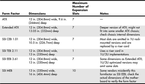
Table 4.2 compares the dimensions and other features of SSI motherboard form factors with ATX motherboard form factors.
Table 4.2 ATX and SSI Motherboard Form Factors Compared
Note
For details on current and older versions of SSI specifications and information about products that meet those specifications, see the SSI website, at www.ssiforum.org.
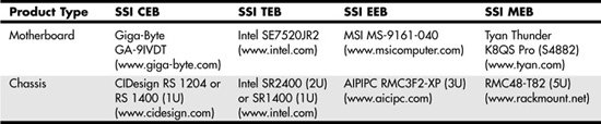
Table 4.3 provides examples of current products that correspond to each SSI form factor.
Table 4.3 Typical Products Based on SSI Chassis and Motherboard Form Factors
The EEB Form Factor
The EEB form factor has essentially the same shape as the Extended ATX form factor: 12 inches by 13 inches (305mmx330mm). Mounting holes used by EEB are the same as those used by ATX specification version 2.1. The I/O connector cluster is also the same as that for ATX. However, EEB supports a 24-pin power connector, following the EPS12V standard rather than the 20-pin ATX power connector standard used on older ATX motherboards. Like ATX, EEB supports up to seven expansion slots.
Another difference between EEB and ATX is EEB's inclusion of an 8-pin 12V power connector for processor power and a 4-pin connector for cooling fans. The additional pin provides control as well as voltage, ground, and sensing features found in 3-pin fan connectors on ATX motherboards. The EEB standard recommends at least five motherboard fan connectors and as many as eight in rack-mounted implementations.
The EEB 24-pin main power connector, 8-pin 12V power connector, and 4-pin cooling fan pinouts are illustrated in Figure 4.6.
Figure 4.6 SSI EEB motherboard (top), processor (lower right), and fan (upper right) power connectors.

The CEB Form Factor
The CEB form factor is similar to the EEB form factor, but the maximum motherboard dimensions are reduced to 12 inchesx10.5 inches (305mmx267mm). Thus, CEB falls between the ATX and EEB form factors in overall dimensions. It uses the same mounting holes as ATX specification version 2.2. The same power and fan connectors shown in Figure 4.6 are also part of the CEB specification.
Figure 4.7 illustrates a typical SSI CEB-compatible motherboard that is optimized for rack-mounted use compared to a typical ATX motherboard. Note the empty spaces reserved for PCI and PCI-X expansion slots; this model uses a riser card for add-on cards. Similar models designed for pedestal servers include the expansion slots not shown in this example.
Figure 4.7 A typical dual-CPU ATX motherboard (top) compared to an SSI CEB motherboard optimized for 1U/2U rack-mounting (bottom).

As you can see from Figure 4.7, an SSI-CEB and an ATX motherboard can have similar features. However, the SSI-CEB motherboard generally has provision for more memory sockets than an ATX motherboard and is a slightly different size (refer to Table 4.2).
The TEB Form Factor
Unlike other SSI specifications, the latest version of the TEB specification, version 2.11, is tailored to the requirements of Intel 64-bit Xeon processors and motherboards based on the E7320, E7520, and E7525 chipsets. TEB is a specification optimized for 1U and 2U rack-mounted servers.
![]() See "The Intel E7520 and E7320 Chipsets," p. 189.
See "The Intel E7520 and E7320 Chipsets," p. 189.
The size of a TEB version 2.11 motherboard is the same as that used by the latest version of EEB: 12 inches by 13 inches (305mmx330mm). Mounting holes used by TEB are the same as those used by ATX specification version 2.1. TEB, unlike EEB and CEB, uses a riser card slot that supports up to three 2U cards or one 1U card rather than multiple PCI, PCI-X, or PCI-Express slots. The riser card connector type is not defined, so a motherboard designer can choose the appropriate type of riser card and slot to use for the job. TEB motherboards use the same power and fan connectors supported by EEB and CEB motherboards (refer to Figure 4.6). TEB motherboards for 2U rack-mounted servers use the same type of I/O port cluster as ATX motherboards, while 1U rack-mounted servers use a thinner version.
The MEB Form Factor
MEB was designed in 1999, at a time when most server processors used bulky Slot 1 or Slot 2 designs. Thus, the MEB form factor has dimensions of 13 inches (330mm) by 16 inches (406.4mm), and it supports up to 10 expansion slots, as well as a memory riser board slot. This standard is now officially obsolete, but some vendors continue to build products based on the MEB standard, primarily for four-way systems.
Note
Some vendors mislabel MEB form factor motherboards as corresponding to the EEB 3.5 standard. To avoid confusion, you should look at the actual dimensions of the motherboard in question. If you are considering motherboards that correspond to the Extended ATX, EEB, or MEB form factors, you should be sure to get a list of recommended enclosures from the motherboard vendor. MEB form factor motherboards do not fit into ATX cases.
Figure 4.8 compares a typical ATX server motherboard (left) to an MEB server motherboard (right).
Figure 4.8 The Tyan Tiger i7501 (S2723) motherboard (left) uses the ATX form factor, whereas the Tyan Thunder K8QS Pro (S4882) motherboard (right) uses the SSI MEB form factor. Photos courtesy of Tyan Computer Corporation.
Backplane Systems
Ever since the first IBM PC was introduced in 1981, the vast majority of PCs and servers have placed major components such as the processor (CPU), chipset, and memory on the motherboard. Expansion slots were used for I/O and display devices. However, some servers and PCs have used a different type of design, known as a backplane system. These systems do not have a motherboard in the true sense of the word. In a backplane system, the components typically found on a motherboard are located instead on one or more expansion adapter cards plugged in to slots.
In these systems, the board with the slots is called a backplane, rather than a motherboard. Systems that use this type of construction are called backplane systems. Backplane systems enable faster swapping of failed components than motherboard-based systems, easier upgrading to faster processors and memory (you swap a single board to make the change), and greater reliability in industrial environments.
Backplane systems come in two main types: passive and active. In a passive backplane, the main backplane board does not contain any circuitry at all except for the bus connectors and maybe some buffer and driver circuits. All the circuitry found on a conventional motherboard is contained on one or more expansion cards installed in slots on the backplane. Some backplane systems use a passive design that incorporates the entire system circuitry into a single mothercard. The mothercard is essentially a complete motherboard designed to plug in to a slot in the passive backplane. The passive backplane/mothercard concept enables you to easily upgrade the entire system by changing one or more cards. The major examples of passive backplane systems in use today include PICMG-based single-board computers and various types of blade servers.
In an active backplane, the main backplane board contains bus control and usually other circuitry as well. Most active backplane systems contain all the circuitry found on a typical motherboard except for the processor complex. The processor complex is the circuit board that contains the main system processor and any other circuitry directly related to it, such as clock control, cache, and so forth. The processor's complex design enables the user to easily upgrade the system later to a new processor type by changing one card. In effect, it amounts to a modular motherboard with a replaceable processor section. Although servers built by IBM, Compaq, and ALR (later absorbed into Gateway) have used this type of design, this type of backplane design is no longer used due to the expense of proprietary processor boards and the advent of easy industry-standard processor upgrades through zero insertion force (ZIF) sockets.
PICMG Backplanes
PICMG has developed a series of specifications for passive-backplane computers for industrial use, including servers. These specifications are listed in Table 4.4.
Table 4.4 PICMG Specifications

Passive backplane systems with mothercards (often called single-board computers [SBCs]) are by far the most popular backplane design. They are used in industrial or laboratory-type systems and are rack mountable. They usually have a large number of slots and extremely heavy-duty power supplies; they also feature high-capacity, reverse flow cooling designed to pressurize the chassis with cool, filtered air. Many passive backplane systems, such as the one pictured in Figure 4.9, adhere to the ePCI-X passive backplane form factor standard set forth by PICMG. You can get more information about these standards from PICMG's website, at www.picmg.org.
Figure 4.9 A typical Xeon PICMG single-board computer. This single card provides PCI and PCI-X interfacing; integrated video; 2 Gigabit Ethernet (10/100/1000) network interfaces; and normal parallel, serial, ATA/IDE, USB, and floppy interfaces.
Figure 4.9 shows a typical dual-Xeon single-board computer used in PICMG 1.2 ePCI-X passive backplane systems. Figure 4.10 shows a rack-mounted chassis with a passive backplane.
Figure 4.10 A rack-mounted chassis with passive backplane.
Blade Servers
Blade servers are the latest development of passive-backplane technology. Multiple server blades of various types can be connected to a single blade server enclosure.
A server blade is a self-contained computer that contains one or more processors, memory, and storage. It differs from a PICMG single-board computer in several ways:
- You can have multiple server blades in a single enclosure, while only one PICMG single-board computer can occupy a backplane. This enables you to place a larger number of servers into a standard rack-mounted enclosure.
- A server blade does not have traditional I/O ports, such as serial, parallel, USB, and VGA ports. Depending on the enclosure, keyboard, video, and mouse (KVM) and other ports might be located on the rear of the enclosure, or all management and I/O might be performed via a network connection.
- Server blades are hot-swappable to reduce downtime and permit quick provisioning of an enclosure.
- Some blades perform network, storage, or management functions, enabling you to combine different types of blades in a single enclosure to customize the performance of your server.
- Some blade server enclosures offer swappable modules at the rear of the enclosure for I/O, networking, and KVM. Although these modules are not hot-swappable, they permit a great deal of customization.
Typical sizes for blade servers include 1U (1.75 inches high) and 3U (5.25 inches high); 3U and larger units permit more flexibility in storage solutions.
Figure 4.11 illustrates two of the many different server blades available, and Figure 4.12 illustrates a blade server enclosure.
Figure 4.11 Some typical server blades.

Figure 4.12 A typical fully populated server blade chassis.

Figures 4.11 and 4.12 make it clear that, unlike traditional and rack-mounted servers that use motherboards or PICMG single-board computers, there is no true standard for blade server technology. Each developer of blade servers uses its own proprietary design for the blades, the chassis, and the I/O and network modules.
![]() To learn more about the development of blade servers and major blade vendors, see "Blade Servers," p. 725. The Sun Microsystems blade server product line is discussed in "Blade Servers," p. 791.
To learn more about the development of blade servers and major blade vendors, see "Blade Servers," p. 725. The Sun Microsystems blade server product line is discussed in "Blade Servers," p. 791.
BTX Motherboards
BTX is a motherboard form factor specification Intel originally released in September 2003, with a 1.0a update in February 2004. BTX may eventually replace the venerable ATX form factor while addressing ever-increasing component power and cooling requirements, as well as enabling improved circuit routing and more flexible chassis designs.
BTX represents a completely new form factor that is not backward compatible with ATX or other designs. A full-size BTX board is 17% larger than an ATX board, allowing room for more integrated components onboard. The I/O connectors, slots, and mounting holes are in different locations than with ATX, requiring new chassis designs. However, the power supply interface connectors are the same as in the latest ATX12V specifications, and newer ATX, TFX, SFX, CFX, and LFX power supplies can be used. The latter two power supply form factors were specifically created to support compact and low-profile BTX systems.
The primary advantages of BTX include the following:
- Optimized inline component layout and routing—The major components (processor and memory modules) are aligned front to back, allowing connections between components and I/O connectors to run unobstructed.
- Optimized airflow path—BTX allows for a condensed system design and an optimized, unobstructed airflow path for efficient system cooling with fewer fans and lower acoustics.
- Support and retention module (SRM)—BTX offers mechanical support for heavy heatsinks. It also helps to prevent board flexing or damaging of board components and traces during shipping and handling.
- Scalable board dimensions—Flexible board sizes enable developers to use the same components for a variety of system sizes and configurations.
- Flexible, compatible power supply designs—Connectors are shared with recent ATX designs; smaller, more efficient power supply form factors can be used for small form factor systems, whereas standard ATX12V power supplies can be used for larger tower configurations.
BTX includes three definitions of motherboard size, as shown in Table 4.5.
Table 4.5 BTX Motherboard Form Factors
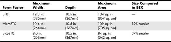
Each board has the same basic screw hole and connector placement requirements. So if you have a case that fits a full-size BTX board, you can also mount a MicroBTX or picoBTX board in that same case (see Figure 4.13). Obviously, if you have a smaller case designed for MicroBTX or picoBTX, you can't put the larger MicroBTX or BTX boards in that case.
Figure 4.13 BTX specification 1.0a motherboard dimensions.
BTX requires up to 10 mounting holes and supports up to seven slots, depending on the size, as shown in Table 4.6.
Table 4.6 BTX Motherboard Mounting Holes

BTX also clearly specifies volumetric zones around the motherboard to prevent any interference from the chassis or internal components, such as drives, which allows for maximum interchangeability without physical interference or fit problems.
With processors exceeding 100W in thermal output, as well as voltage regulators, motherboard chipsets, and video cards adding to the thermal load in a system, BTX was designed to allow all the high-heat-producing core components to be mounted inline from front to back so that a single high-efficiency thermal module (heatsink) can cool the system. This eliminates the need for an excessive number of fans. The thermal module includes a heatsink for the processor, a high-efficiency fan, and a duct to direct airflow through the system. Extra support for the thermal module is provided under the board via a support and retention module (SRM), which provides structural support for heatsinks that are much heavier than allowed in ATX designs. The thermal module pulls air directly from the front of the case over the processor and memory for better cooling than with ATX systems.
BTX uses the same power connectors as in the latest ATX12V v2.x power supply form factor specifications, including a 24-pin main connector for the board and a 4-pin ATX12V connector for the CPU voltage regulator module. The particular power supply form factor used depends mostly on the chassis selected.
A typical tower system has components arranged as shown in Figure 4.14.
Figure 4.14 BTX tower chassis layout.

From Figure 4.14, you can see that the main heat-producing core components are centrally located inline from front to rear, allowing the most efficient thermal design. Air flows from front to rear through the center, cooling the processor, motherboard chipset, memory, and video card.
To support the heavy processor heatsink and thermal module assembly, an SRM is mounted under the board. The SRM is essentially a metal plate affixed to the chassis under the board, and the thermal module is bolted directly to the SRM instead of to the motherboard. This helps carry the weight of the module and prevents excessive loads from being applied to the processor and motherboard, especially during the shipping and handling of the system.
The BTX I/O connector area is similar to ATX, except that it is at the opposite side of the rear of the board. The size of the area is slightly shorter but wider than ATX, allowing a large number of interfaces and connectors to be built in to the motherboard.
As of early 2006, only a few BTX servers were available in the marketplace. It remains to be seen whether BTX will replace ATX at some point or will become unnecessary as both Intel and AMD introduce lower-wattage processors in 2006 and beyond.
Proprietary Server Designs
Proprietary server designs aren't limited to the world of blade servers. Many four-way and almost all eight-way or larger servers use proprietary designs. There are several reasons for this:
- These systems are designed for upgrading at a processor, memory, and storage level rather than a motherboard level.
- Motherboard form factors such as ATX and its server offshoots, such as SSI, are not suitable for very large systems.
- ATX, BTX, and SSI standards do not support hot-swapping of processors and memory.
- ATX, BTX, and SSI do not support fault-tolerant system designs.
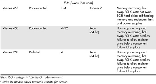
For these reasons, proprietary designs have been and will continue to be popular. All servers running RISC processors are, by definition, proprietary. Itanium-based processors also use proprietary designs. However, systems running x86 processors might also feature proprietary designs. Table 4.7 lists some of the major proprietary server designs available from major vendors.
Table 4.7 x86 and Itanium 2-Based Proprietary Server Designs1
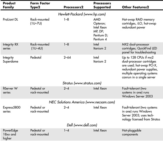
One of the benefits of considering proprietary server designs is the greater emphasis on redundancy and hot-swapping of defective hardware that is possible. While many midrange and high-end servers feature various levels of fault-tolerant design, such as hot-swap memory, fans, and drives, it's still possible for a failure in another part of the server to cripple the unit or shut it down entirely. If your business depends on true 24x7x365 reliability from a server, you might want to consider a server that replicates every major component and processes information in parallel. This type of server is known as a fault-tolerant server.
Fault-Tolerant Servers
Because fault-tolerant servers process information in parallel, using two or three replicated systems in one, a failure in one part of the server does not cause data loss or even require a shutdown; the parallel components continue to work and provide the information needed.
Major vendors of fault-tolerant servers include Stratus, NEC, and Hewlett-Packard. Their products are discussed in the following sections.
Stratus ftServer and Continuum Servers
Stratus (www.stratus.com) offers several lines of fault-tolerant servers:
- The ftServer W series runs Windows Server 2003 and supports Xeon processors. It offers up to four-way fault-tolerant operation.
- The ftServer T series runs Red Hat Enterprise Linux and supports Xeon processors. It offers up to four-way fault-tolerant operation.
- The ftServer V series runs Stratus's own VOS operating system. Stratus provides migration tools and support to move existing applications to VOS. The V Series also supports Xeon processors and offers up to four-way fault-tolerant operation.
- The Stratus Continuum series runs VOS; the Continuum 400 also runs HP-UX (the Hewlett-Packard version of UNIX).
The ftServer W and T series are roughly comparable to the NEC Express5800 series (discussed in the next section). Because they run Windows Server 2003 or Linux, they would be easy to add to any network already running those operating systems.
NEC Express5800 Series
NEC (www.necsam.com) offers a line of fault-tolerant servers known as the Express5800 series. The Express5800 series offers both Linux and Windows Server 2003–based systems with up to four-way Xeon processors. The Express5800 series uses technology licensed from Stratus.
Hewlett-Packard Integrity NonStop Series
Hewlett-Packard (www.hp.com) offers a line of fault-tolerant servers known as the Integrity NonStop series. The Integrity NonStop series, introduced in 2005, differs from the previous NonStop series because it uses Intel Itanium 2 processors, whereas the previous NonStop servers used Silicon Graphics MIPS S88000 processors.
Hewlett-Packard refers to its fault-tolerant design as NonStop Advanced Architecture (NSAA). NSAA is designed to provide fault tolerance at both software and hardware levels. Therefore, Integrity NonStop servers run a specially designed operating system and applications.
The Integrity NonStop series is designed to handle much larger server tasks than the Stratus W or T series or the NEC Express5800 series, with scalability up to 4,080 processors and up to 64TB of memory.
Power Supplies and Connectors
Servers based on the ATX or microATX form factors generally use an ATX power supply, while pedestal servers based on one of the SSI form factors generally use an EPS12V power supply. Servers that use proprietary form factors, as well as many slimline 1U and 2U servers, use various form factors. The following sections deal with standard types of power supplies and connectors, including ATX, ATX12, and EPS12V, among others.
ATX Power Supply Standards
ATX power supplies were originally designed for use in desktop computers, and they are also widely used in entry-level tower and slimline servers. ATX power supply standards include the following:
- ATX version 2.03—Older entry-level tower servers
- ATX12V—More recent entry-level tower servers
- ATX1U—1U slimline servers
- ATX2U—2U slimline servers
The following sections provide information on these power supply standards.
ATX/ATX12V Power Supplies and Connectors
Motherboards that support the ATX version 2.03 power supply use a 20-pin main power connector, as shown in Figure 4.15.
Figure 4.15—The ATX version 2.03 power supply connector uses a positive-locking plug to secure the power supply cable.
Some servers may also feature a 6-pin auxiliary power connector, as shown in Figure 4.16. This additional connector provides additional 3.3V and 5V power to the motherboard. ATX power supplies with ratings of 250 watts or more feature this connector, but if your motherboard does not feature this connector, you can just leave the auxiliary power connector unconnected.
Figure 4.16 ATX auxiliary power connector.
Most recent servers that use ATX power supplies also feature a 4-pin connector called the ATX12V connector, shown in Figure 4.17. This connector provides additional 12V power to meet the requirements of newer processors, such as the Pentium 4.
Figure 4.17 An ATX12V power connector.

Power supplies that feature the ATX12V connector shown in Figure 4.17 are known as ATX12V power supplies. Most ATX power supplies on the market today, particularly those with 300w or higher ratings, meet ATX12V standards. ATX12V version 1.x power supplies also include the 6-pin auxiliary connector, although most recent servers do not use it.
Figure 4.18 illustrates a typical ATX12V v1.x power supply. Note the 4-pin floppy and hard disk power cables shown above the 20-pin main power supply cable.
Figure 4.18 An ATX12V v1.x power supply.
The ATX12V version 2.0 power supply standard was introduced in 2003. The 6-pin auxiliary connector was discontinued, and the main power connector was enlarged from 20 pins to 24 pins, using the Molex 39-01-2240 connector. ATX12V version 2.0 and newer connectors also feature integrated power supply connectors for SATA drives, which are increasingly common today. Figure 4.19 compares the 20-pin ATX and 24-pin ATX12V version 2.x power supply connectors to each other. The 24-pin ATX12V version 2.x connector uses the same physical connectors as the ATX-GES and EPX12V power supply connectors used in multiple-processor servers.
Figure 4.19 The ATX 2.03 power supply connector (left) and ATX12V 2.x power supply connector (right).
Figure 4.20 compares the motherboard connectors and pinouts used by these power supplies.
Figure 4.20 Pinouts for the ATX2.03/ATX12V v1.x (top) and ATX12V 2.x (bottom) power supplies.
Tip
If your server uses the 20-pin ATX power supply connector, you can use the newer ATX12V v2.x power supply by using a 20-pin–to–24-pin adapter. Many power supply vendors ship such an adapter with their ATX12V v2.x power supplies, or you can purchase it separately.
ATX1U/2U Rack-Mounted Power Supplies
Rack-mounted servers use a variety of power supply standards. Although most 1U and 2U servers use the power supply standards developed by the SSI Forum, some use the ATX1U and ATX2U power supply standards discussed in this section.
![]() See "SSI Rack-Mounted Power Supply Standards," p. 253.
See "SSI Rack-Mounted Power Supply Standards," p. 253.
The ATX1U and ATX2U power supply standards use the same 20-pin ATX power supply, floppy, and hard disk power connectors used by the ATX 2.03 and ATX12V v1.x power supply standards (refer to Figure 4.14). Some 200w and larger ATX1U power supplies also feature the 4-pin ATX12V power supply connector (refer to Figure 4.17), while ATX2U power supplies feature the 6-pin auxiliary power supply connector shown in Figure 4.15.
Figure 4.21 illustrates typical ATX1U and ATX2U power supplies.
Figure 4.21 Typical ATX1U (top) and ATX2U (bottom) power supplies.

Typical ATX1U power supplies use two 40mm fans for cooling, one at the front and one at the back. Typical ATX2U power supplies use a 60mm fan for cooling.
SSI Power Supply Standards
The SSI Forum has developed a series of power supply and connector form factors designed for use in various types of servers. These include the following:
- EPS12V—Nonredundant power supply for pedestal-mounted servers
- ERP12V—Redundant power supply for pedestal-mounted servers
- EPS1U—Nonredundant power supply for 1U rack-mounted servers
- EPS2U—Nonredundant power supply for 2U rack-mounted servers
- ERP2U—Redundant power supply for 2U rack-mounted servers
- PSMI—Power Supply Management Interface
The following sections provide details of these power supplies and connectors.
SSI Pedestal Power Supply and Connector Standards
The ATX12V v2.x power supply standard discussed earlier in this chapter is actually based on the SSI Forum's EPS12V standard, one of the power supply standards developed by the SSI Forum for use in servers.
![]() See "SSI Form Factor Specifications," p. 234.
See "SSI Form Factor Specifications," p. 234.
Because both standards are sponsored in part by Intel, it should not be surprising that features from the SSI EPS power supply standard should eventually find their way into the ATX standard. The EPS12V and ATX12V v2.x power supplies use the same 24-pin connector and the same pinout (refer to Figures 4.18 and 4.19). However, the EPS12V power supply differs from the ATX12V v2.x power supply by providing an 8-pin 12V connector rather than the 4-pin 12V connector shown in Figure 4.17. The additional 12V lines provide sufficient 12V power for multiple-processor motherboards. (Recent and current processors use voltage regulators powered by 12V lines rather than 5V lines as with older processors.)
Note
For motherboards equipped with a 4-pin 12V connector, you can plug the 8-pin cable into the 4-pin connector without needing an adaptor.
An EPS12V power supply closely resembles an ATX12V v2.0 power supply except that an EPS12V unit is somewhat deeper. An ATX power supply has a maximum depth of 140mm, while an EPS12V power supply can be as much as 230mm deep. Because an EPS12V power supply can be used in place of an ATX power supply if the chassis permits, some vendors refer to EPS12V power supplies as "extended ATX" power supplies. If you want to use an EPS12V power supply in a server chassis designed for ATX hardware, check the space available for the power supply and compare it to the depth of the EPS12V power supply you are considering.
ERP12V power supplies use the same connectors and form factor as EPS12V power supplies, but they contain two or, occasionally, three removable power supply modules. Generally, each module has its own AC power cord. By connecting each module to a different circuit, you have protection against AC power failure as well as against power supply module failure.
![]() For more information about redundant power supplies, see "Redundant Power Supplies (RPSs)," p. 675.
For more information about redundant power supplies, see "Redundant Power Supplies (RPSs)," p. 675.
SSI Rack-Mounted Power Supply Standards
Although the EPS12V power supply can be considered a "supersized" power supply in both features and form factors, EPS power supply standards for rack-mounted 1U and 2U servers feature much different form factors. While the EPS1U and EPS2U power supplies use the same 24-pin main power connector and other power connectors used by the EPS12V power supply, they feature slimmer form factors designed to fit in rack-mounted cabinets and provide adequate cooling.
Typical EPS1U power supply designs feature a trio of 40mm fans: one at the front of the power supply and two at the rear. Typical EPS2U power supply designs feature a 60mm fan. See Figure 4.22.
Figure 4.22 Typical EPS1U (top) and EPS2U (bottom) power supplies.

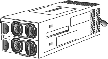
SSI has also developed the ERP2U standard for redundant 2U rack-mounted power supplies. Essentially, an ERP2U power supply contains two removable power supply modules similar in size to the ESP1U power supply shown in Figure 4.22. A folding handle can be flipped upright to enable each module to be removed. ERP2U power supplies use the same connectors as other SSI power supplies. See Figure 4.23 for a typical example.
Figure 4.23 Rear view of a typical ERP2U redundant power supply.
ATX GES and WTX Power Supply Connectors
Although all recent x86 server motherboards with 24-pin connections are designed to use either ATX12V v2.x or EPS12V power supplies, some servers use one of two other power supply standards:
- AMD developed the ATX GES power supply standard to support its first server-class processor, the Athlon MP, when used in dual-processor (two-way) configurations.
- Some servers based on the Intel 860 chipset used a version of the WTX power supply standard.
Caution
Because the ATX GES and WTX power supplies use different pinouts than the ATX12V and EPS12V power supplies, if you install an ATX GES or WTX-compatible power supply in a server designed to use ATX12V v2.x or EPS12V, or vice versa, you will damage the motherboard and power supply.
The WTX power supply pinout listed in Table 4.8 was used primarily by motherboards based on the Intel 860 chipset and the first-generation Xeon processor based on the Pentium 4. These motherboards include the Tyan S2608 (Thunder i860), Iwill DP400, and MSI MS-6508. These motherboards also used a 6-pin CPU power supply connector to provide additional power for the motherboard's CPU power regulator.
Table 4.8 ATX-GES, EPS12V, and WTX 24-Pin Primary Power Connector Pinouts

The ATX GES power supply standard shown in Table 4.8 was used by the Tyan Thunder K7 (S2452 series) and Tyan Thunder K7X (S2468 series) motherboards made for the AMD Athlon MP processor. Note that the Tyan Thunder K7X Pro uses an EPS12V power supply.
Table 4.8 compares the pinouts of the ATX-GES, WTX, and EPS12V/ATX12V v2.x 24-pin primary power connectors.
If you need to replace the power supply in a server, be sure to verify what standard it uses. Some power supply vendors list specific motherboards or system compatibility information on their websites to help you select the correct power supply.
Note
The ATX GES power supply also uses an 8-pin processor power connector: Pin 1 provides +5V, pin 2 is used for power good, pins 3–5 provides ground, and pins 6–8 provide +12V. The WTX power supply also uses a 6-pin processor power connector: pins 1–3 provide +12V, and pins 4–6 are signal grounds.
Server Motherboard Components
As the previous section indicates, the power supply is a very important part of server design. Power supply designs have been developed in conjunction with motherboard designs to make sure there is enough power to operate the many components built in to, or plugged in to, modern server motherboards.
Most modern server motherboards have at least the following major components on them:
- Processor socket(s)/slot(s)
- Chipset (North Bridge/South Bridge or memory and I/O controller hubs)
- Super I/O chip
- ROM BIOS (Flash ROM/firmware hub)
- DIMM/RIMM (RAM memory) sockets
- PCI/PCI-X/PCI-Express bus slots
- CPU voltage regulator
- Battery
- Integrated PCI or low-end AGP video
- Integrated Fast (10/100) or Gigabit (10/100/1000) Ethernet
Many boards also have Serial ATA (SATA) or SCSI RAID interfaces onboard.
These standard components are discussed in the following sections.
Processor Sockets and Slots
Server motherboards often support two or more processors. Depending on the server and processor type, the processor might be installed in a ZIF socket for easy insertion and removal, a single-processor cartridge, or a proprietary multiprocessor cartridge. Most recent servers use socketed processors, but a few high-end servers use proprietary processor cartridges. For example, the Hewlett-Packard Integrity rx and Superdome series can use either standard Intel Itanium 2 processors or proprietary mx2 two-processor cartridges.
Typically, systems based on the ATX, BTX, and SSI motherboard form factors support up to four processors. Most systems with more than four processors use proprietary motherboard designs. Note that servers that use proprietary motherboards (primarily four-way or larger) often use proprietary processor boards. The processor board might provide enhanced cooling features not present with standard processor sockets. See the vendor's instructions for adding or removing processors in servers that use processor boards or cartridges.
![]() See "Processor Socket and Slot Types," p. 62.
See "Processor Socket and Slot Types," p. 62.
Single Versus Dual-/Multiple-Processor Sockets
One of the factors that influences what motherboard to use in a server is the number of processors you want it to support initially and in the future. A standard ATX motherboard can support up to two socketed processors. However, if more processors are needed, larger form factors must be used. Table 4.9 lists the maximum number of processors supported by industry-standard form factors.
Table 4.9 The Number of Processors Supported by Motherboard Form Factors

Note that the number of processors supported by a blade server is the number of processors per blade multiplied by the number of server blades per chassis. Thus, if a chassis can support 10 server blades, and each server blade can hold two processors, the blade server chassis contains up to 20 processors.
Chipsets and Super I/O Chips
Although several server motherboards might have the same form factor, the processors, memory types, and other features they support are controlled by the chipset used by the motherboard designer. The chipset is the motherboard; therefore, any two boards with the same chipsets are functionally identical unless the vendor has added features to those provided by the chipset or removed support for certain chipset features.
The chipset contains the processor bus interface (called front-side bus [FSB]), memory controllers, bus controllers, I/O controllers, and more. All the circuits of the motherboard are contained within the chipset. Because the chipset controls all the major features of the system, including the processor, we recommend selecting the chipset as the first part of the server selection process.
Chipsets designed with server use in mind vary from desktop PC chipsets in several ways, including the following:
- Support for memory-reliability technologies such as error-correcting-code (ECC) and registered SDRAM and DDR RAM
- Support for PCI-X expansion slots (a faster, wider version of PCI that supports 64-bit operation and speeds up to 133MHz); PCI-X is backward compatible with PCI
- Support for two-way and higher processor counts (when feasible); the ability to run multiple-processor configurations is affected by the processor used. For example, the Pentium 4, Pentium D, and AMD Opteron 1xx series support single-processor configurations only, and the Xeon DP and Opteron 2xx series support dual-processor configurations. The Xeon MP and Opteron 8xx support higher numbers of processors.
Major chipset vendors for servers include Intel, ServerWorks, AMD, and nVidia. See Chapter 3, "Server Chipsets," for more information.
The third major chip on many server motherboards is called the Super I/O chip. This is a chip that integrates legacy devices such as floppy controllers and serial, parallel, PS/2 mouse, and keyboard ports. Increasingly, the South Bridge chip incorporates the Super I/O chip's functions.
Memory: SIMM/DIMM/RIMM/SDRAM/DDR
You should consider the type and speed of memory used by a particular server or server-class motherboard when you select or build a server. Server memory differs from desktop PC memory in several ways:
- Many servers still use PC100 or PC133 SDRAM rather than the newer DDR memory. Because its use is no longer widespread and less of it is produced, SDRAM memory is actually now more expensive than DDR memory. If you are upgrading multiple servers, the additional cost could be significant.
- Most servers use registered memory rather than the unbuffered memory used by desktop PCs. Registered memory contains a small buffer chip to improve signal strength, which is very important for memory reliability in large modules.
- Virtually all servers include ECC features in the chipset and BIOS. ECC uses the parity bit to correct single-bit memory errors and report larger memory errors. Many high-end servers include additional memory-reliability features such as hot-swapping memory and memory scrubbing.
Registered ECC memory modules are more expensive than the normal unbuffered, non-parity memory used by desktop PCs, but the extra reliability provided by these features makes the extra cost worthwhile.
The most common types of memory used by servers include the following:
- PC100 or PC133 registered SDRAM with ECC
- Various speeds of registered DDR SDRAM with ECC
- Various speeds of registered DDR2 SDRAM with ECC
Older servers might use one of these types of memory:
- PC66 registered SDRAM with ECC
- Rambus RDRAM with ECC
- EDO DRAM with ECC
For more information about memory types, see Chapter 5, "Memory."
Expansion Slots: ISA, PCI, AGP, and Others
Although today's servers have more integrated devices than ever before, the number and type(s) of expansion slots available is still an important factor to consider when building or buying a server.
The most common expansion slot types found on recent servers include the following:
- PCI—Although desktop computers normally use only the 32-bit/33MHz version of PCI, servers often use 64-bit/66MHz slots (which are backward compatible with 32-bit/33MHz versions).
- PCI-X—PCI-X runs at much faster speeds than PCI, making it an excellent choice for high-performance network adapters or RAID host adapters. PCI-X slots are backward compatible with PCI cards.
If you support or find yourself working on older servers, particularly those used in industrial applications, you might also encounter systems that still support ISA and EISA slots. On the other end of the spectrum, PCI-Express is an emerging technology found in some of the latest servers. Eventually you can expect it to replace PCI and PCI-X.
Finally, there's AGP. Although AGP is a very important bus type for desktop PCs, it is seldom found in servers except for low-end systems also suitable for workstation use.
The following sections discuss these slot designs in greater detail.
ISA Slots
Industry Standard Architecture (ISA) is the bus architecture that was introduced as an 8-bit bus with the original IBM PC in 1981; it was later expanded to 16 bits with the IBM PC/AT in 1984. ISA is the basis of the modern PC and was the primary architecture used in the vast majority of PC systems until the late 1990s. It might seem amazing that such a presumably antiquated architecture was used for so long, but it provided reliability, affordability, and compatibility, plus this old bus is still faster than many of the peripherals connected to it.
Note
The ISA bus hasn't been seen in either standard servers or desktop PCs for several years. However, it continues to be used in industrial computer (PICMG) designs. That said, it is expected to eventually fade away from those systems as well.
Two versions of the ISA bus exist, based on the number of data bits that can be transferred on the bus at a time. The older version is an 8-bit bus; the newer version is a 16-bit bus. The original 8-bit version ran at 4.77MHz in the PC and XT, and the 16-bit version used in the AT ran at 6MHz and then 8MHz. Later, the industry as a whole agreed on an 8.33MHz maximum standard speed for 8-/16-bit versions of the ISA bus for backward compatibility. Some systems have the capability to run the ISA bus faster than this, but some adapter cards do not function properly at higher speeds. ISA data transfers require anywhere from two to eight cycles. Therefore, the theoretical maximum data rate of the ISA bus is about 8MBps, as the following formula shows:
8.33MHz x 2 bytes (16 bits) ÷ 2 cycles per transfer = 8.33MBps
The bandwidth of the 8-bit bus would be half this figure (4.17MBps). Remember, however, that these figures are theoretical maximums. Because of I/O bus protocols, the effective bandwidth is much lower—typically by almost half. Even so, at about 8MBps, the ISA bus is still faster than many of the peripherals connected to it, such as serial ports, parallel ports, floppy controllers, keyboard controllers, and so on.
Figure 4.24 describes the pinouts for the full 16-bit ISA expansion slot (8-bit ISA cards plug in to the top portion of the slot only), and Figure 4.25 shows how the additional pins are oriented in the expansion slot.
The dimensions of a typical AT expansion board are as follows:
- 4.8 inches (121.92mm) high
- 13.13 inches (333.5mm) long
- 0.5 inches (12.7mm) wide
Figure 4.24 Pinouts for the 16-bit ISA bus.
Figure 4.25 The ISA 16-bit bus connector.

The EISA Bus
The EISA standard was developed primarily by Compaq in 1988. EISA was the company's attempt at taking over future development of the PC bus from IBM. Compaq formed the EISA committee, a nonprofit organization designed specifically to control development of the EISA bus, and provided the bus designs freely to other vendors. Unfortunately, very few EISA adapters were ever developed. Those that were developed centered mainly around disk array controllers and server-type network cards.
The EISA bus was essentially a 32-bit version of ISA that provided full backward compatibility with 8-bit or 16-bit ISA cards. EISA cards use automatic configuration via software.
The EISA bus added 90 new connections (55 new signals plus grounds) without increasing the physical connector size of the 16-bit ISA bus. At first glance, the 32-bit EISA slot looks a lot like the 16-bit ISA slot. However, the EISA adapter has two rows of stacked contacts. The first row is the same type used in 16-bit ISA cards; the other, thinner row extends from the 16-bit connectors. Therefore, ISA cards can still be used in EISA bus slots. Although this compatibility was not enough to ensure the popularity of EISA buses, it is a feature that was carried over into the desktop VL-Bus standard that followed. The physical specifications of an EISA card are as follows:
- 5 inches (127mm) high
- 13.13 inches (333.5mm) long
- 0.5 inches (12.7mm) wide
The EISA bus can handle up to 32 bits of data at an 8.33MHz cycle rate. Most data transfers require a minimum of two cycles, although faster cycle rates are possible if an adapter card provides tight timing specifications. The maximum bandwidth on the bus is 33MBps, as the following formula shows:
8.33MHz x 4 bytes (32 bits) = 33MBps
Figure 4.26 describes the pinouts for the EISA bus. Figure 4.27 shows the locations of the pins; note that some pins are offset to allow the EISA slot to accept ISA cards. Figure 4.28 shows the card connector for the EISA expansion slot.
Figure 4.26 Pinouts for the EISA bus.

Figure 4.27 Pin locations inside the EISA bus connector.
Figure 4.28 The EISA bus connector.
PCI, PCI-X, and PCI-Express
In early 1992, recognizing the need to overcome weaknesses in the ISA and EISA buses, Intel spearheaded the creation of another industry group: the PCI Special Interest Group (PCI-SIG). This group was formed with the same goals as the VESA group in relation to the PC bus.
The PCI bus specification was released in June 1992 as version 1.0 and since then, it has undergone several upgrades. Table 4.10 shows the various releases of PCI.
Table 4.10 PCI Specifications

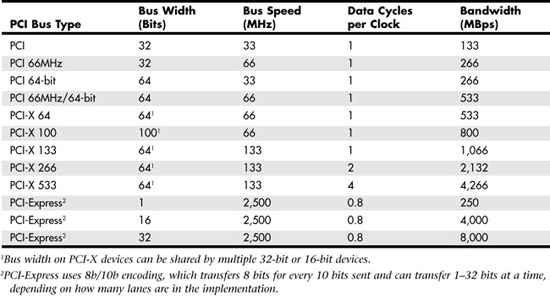
Servers typically offer a mixture of PCI and PCI-X or PCI-X and PCI-Express slots. The specifications for different types of PCI slots are listed in Table 4.11.
Table 4.11 PCI Bus Types
Aiding performance is the fact that the PCI bus can operate concurrently with the processor bus; it does not supplant it. The CPU can be processing data in an external cache while the PCI bus is busy transferring information between other parts of the system; this is a major design benefit of the PCI bus.
The PCI specification identifies three board configurations, each designed for a specific type of system with specific power requirements; each specification has a 32-bit version and a longer 64-bit version. The 5V specification is for stationary computer systems (using PCI 2.2 or earlier versions), the 3.3V specification is for portable systems (also supported by PCI 2.3), and the universal specification is for motherboards and cards that work in either type of system. 64-bit versions of the 5V and universal PCI slots are found primarily on server motherboards. The PCI-X 2.0 specifications for 266 and 533 versions support 3.3V and 1.5V signaling; this corresponds to PCI version 2.3, which supports 3.3V signaling. PCI-X slots also support PCI cards.
Unlike older card designs, such as ISA and EISA, PCI does not use jumper blocks or DIP switches for configuration. Instead, software or a Plug and Play (PnP) BIOS does the configuration. This was the model for the Intel PnP specification. True PnP systems are capable of automatically configuring the adapters.
PCI-SIG developed PCI-Express during 2001–2002, based on the 3GIO draft high-speed bus specification originally developed by the Arapahoe Work Group (a work group led primarily by Intel). The initial PCI-Express 1.0 specification was released in 2002. However, the first systems to use PCI-Express slots did not appear until 2004.
The key features of PCI-Express are as follows:
- Compatibility with existing PCI enumeration and software device drivers
- Physical connection over copper, optical, or other physical media to allow for future encoding schemes
- Maximum bandwidth per pin, which allows small form factors, reduced cost, simpler board designs and routing, and reduced signal integrity issues
- An embedded clocking scheme, which enables easy frequency (speed) changes compared to synchronous clocking
- Bandwidth (throughput) that can increase easily with frequency and width (lane) increases
- Low latency, suitable for applications that require isochronous (time-sensitive) data delivery, such as streaming video
- Hot-plugging and hot-swapping capabilities
- Power management capabilities
PCI-Express, like other high-speed interfaces, such as SATA, USB 2.0, and IEEE 1394 (FireWire or i.LINK), uses a serial bus for signaling. A serial bus sends 1 bit at a time over a single wire at very high speeds. Serial bus signaling avoids the problems caused by parallel buses such as PCI and PCI-X, which must synchronize multiple bits sent simultaneously and may have problems with jitter or propagation delays.
PCI-Express is a very fast serial bus design that is backward compatible with current PCI parallel bus software drivers and controls. In PCI-Express, data is sent full-duplex (that is, via simultaneously operating one-way paths) over two pairs of differentially signaled wires called a lane. Each lane allows for about 250MBps throughput in each direction initially, and the design allows for scaling from 1 to 2, 4, 8, 16, or 32 lanes. The most common configurations in PCs and servers are x1 (one lane), x4, and x16.
For example, a high-bandwidth configuration with eight lanes allowing 8 bits to be sent in each direction simultaneously would allow up to 2000MBps bandwidth (each way) and use a total of only 40 pins (32 for the differential data pairs and 8 for control). Future increases in signaling speed could increase that to 8000MBps each way over the same 40 pins. This compares to PCI, which has only 133MBps bandwidth (one way at a time) and requires more than 100 pins to carry the signals. For expansion cards, PCI-Express takes on the physical format of a smaller connector that appears adjacent to any existing PCI slots on the motherboard. Figure 4.29 shows how PCI-Express x1 and x16 slots compare to 33MHz PCI and 133MHz PCI-X expansion slots.
Figure 4.29 PCI-X, PCI-Express x16, PCI, and PCI-Express x1 slots compared to each other.
PCI-Express uses an IBM-designed 8-bit–to–10-bit encoding scheme, which allows for self-clocked signals that easily allow future increases in frequency. The starting frequency is 2.5GHz, and the specification allows increasing up to 10GHz in the future, which is about the limit of copper connections. By combining frequency increases with the capability to use up to 32 lanes, PCI-Express will be capable of supporting future bandwidths up to 32GBps.
PCI-Express is designed to augment and eventually replace many of the buses currently used in PCs and servers. In addition, it will replace video interfaces such as AGP and act as a mezzanine bus to attach other interfaces, such as SATA, USB 2.0, IEEE 1394b, Gigabit Ethernet, and more. Currently, PCI-Express is used alongside PCI-X and PCI slots, as Figure 4.29 suggests.
Because PCI-Express can be implemented over cables as well as onboard, it can be used to create systems constructed with remote "bricks" that contain the bulk of the computing power. Imagine the motherboard, processor, and RAM in one small box, hidden under a table, with the video, disk drives, and I/O ports in another box, sitting out on a table within easy reach. This will enable a variety of flexible PC form factors to be developed in the future without compromising performance.
For more information on PCI-Express, you can consult the PCI-SIG website (www.pcisig.org).
The AGP Bus
The AGP bus was created in 1996 by Intel specifically for high-performance graphics and video support. Although the PnP BIOS treats AGP like a PCI slot in terms of IRQ and other hardware resources, it uses different connectors and is otherwise separate from PCI.
Table 4.12 lists the various versions of AGP that have been developed for PCs. Although you might find AGP slots in some servers, systems with AGP slots are primarily workstation or PC systems. Currently, servers don't need anything other than basic 2D GUI graphics for system management, and therefore most servers use PCI-based graphics, such as the ATI Rage XL, on the motherboard.
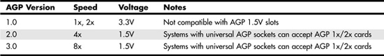
Table 4.12 AGP Versions and Specifications
We recommend using AGP video in a server only if you cannot use PCI video—for example, if you run out of PCI slots and your server does not incorporate video. If you need to use AGP video, keep in mind the differences between AGP slots:
- Most recent AGP video cards are designed to conform to the AGP 4X or AGP 8X specification, each of which runs on only 1.5 volts.
- Most older motherboards with AGP 2X slots are designed to accept only 3.3V cards.
If you plug a 1.5V card in to a 3.3V slot, both the card and motherboard could be damaged, so special keys have been incorporated into the AGP specification to prevent such disasters. Normally, the slots and cards are keyed such that 1.5V cards fit only in 1.5V sockets, and 3.3V cards fit only in 3.3V sockets. However, universal sockets do exist that accept either 1.5V or 3.3V cards. The keying for the AGP cards and connectors is dictated by the AGP standard, as shown in Figure 4.30.
Figure 4.30 AGP 4X/8X (1.5V) card and AGP 3.3V, universal, and 1.5V slots.
As you can see from Figure 4.30, AGP 4X or 8X (1.5V) cards fit only in 1.5V or universal (3.3V or 1.5V) slots. Due to the design of the connector and card keys, a 1.5V card cannot be inserted into a 3.3V slot.
Caution
Some AGP 4x/8x-compatible motherboards require you to use 1.5V AGP 4x/8x cards only; be sure to check compatibility between the motherboard and the AGP card you want to buy to avoid problems. Some AGP 4x/8x-compatible slots use the card retention mechanism shown in Figure 4.31. Note that AGP 1x/2x slots have a visible divider not present on the newer AGP 4x/8x slot. AGP 4x slots can also accept AGP 8x cards and vice versa.
Figure 4.31 AGP standard (1x/2x), AGP 4x, and AGP Pro slots compared. AGP 4x and AGP Pro can accept AGP 1x, 2x, and 4x cards. AGP 4x and AGP Pro slots can also accept AGP 8x cards.

Server/workstation motherboards with AGP slots might use a variation known as AGP Pro, now in version 1.1a. AGP Pro defines a slightly longer slot with additional power pins at each end to drive bigger and faster AGP cards that consume more than 25 watts of power, up to a maximum of 110 watts. AGP Pro slots are backward compatible, meaning that a standard AGP card can plug in, and a number of motherboard vendors have used AGP Pro slots rather than AGP 4x slots in their products. Because AGP Pro slots are longer, an AGP 1x/2x card can be incorrectly inserted into the slot, which could damage it, so some vendors supply a cover or an insert for the AGP Pro extension at the rear of the slot. This protective cover or insert should be removed only if you want to install an AGP Pro card.
Figure 4.31 compares the standard AGP 1x/2x, AGP 4x, and AGP Pro slots.
CPU Voltage Regulators
Because virtually all x86 processors run on a fraction of 3.3V DC (the lowest power level available from a server's power supply), server and PC motherboards alike feature voltage regulators. Occasionally the voltage regulator is built in to a removable daughtercard, but in most cases, the voltage regulator is built in to the motherboard. The voltage regulator uses a series of capacitors and coils and is usually located near the processor socket(s) or slot(s). Figure 4.32 shows the location of a typical voltage regulator on a typical server motherboard.
Figure 4.32 Voltage regulator components on a typical server motherboard.

If you plan to use an aftermarket active or passive heatsink to cool your processor(s), you should be sure to check the clearance between the processor socket(s) and the voltage regulator's components. Some voltage regulators are located so close to the processor socket(s) that extra-large heatsinks cannot be used.
BIOS Chips
The BIOS chip in any given server might take one of the following forms:
- A socketed chip
- A surface-mounted chip
The BIOS chip provides the interface between the operating system and the motherboard's onboard hardware. In virtually any server built in the past decade, the BIOS chip's contents can be updated through software. BIOSs that support software updating are known as flash BIOS chips.
BIOS settings are stored in a separate chip known as the CMOS chip or as the nonvolatile RAM/real-time clock (NVRAM/RTC) chip.
![]() For more information on configuring the system BIOS, see "ROM BIOS," p. 286.
For more information on configuring the system BIOS, see "ROM BIOS," p. 286.
CMOS Battery
A small battery on the motherboard, often called the CMOS battery, maintains the BIOS settings stored in the CMOS and maintains clock timing when the server is turned off.
If the CMOS battery's voltage falls below minimum amounts, the system clock loses time, and eventually CMOS settings are lost. When that happens, the BIOS returns to its default settings the next time power is restored. Most recent servers use the same CR2032 3V lithium watch battery used by most recent desktop PCs. However, some older servers use other battery types, including rechargeable Ni-Cad battery packs or chips that incorporate battery and CMOS RAM/RTC. See your server or motherboard manual for details.
Figure 4.33 shows a BIOS chip and CMOS battery on a typical server motherboard.
Figure 4.33 Voltage regulator components on a typical server motherboard.
System Resources
System resources are the communications channels, addresses, and other signals hardware devices use to communicate on the bus of an x86 or Itanium-based server. At their lowest level, these resources typically include the following:
- Memory addresses
- IRQ (interrupt request) channels
- DMA channels
- I/O port addresses
These are listed roughly in the order in which you would experience problems with them. Memory conflicts are perhaps the most troublesome of these and certainly the most difficult to fully explain and overcome. Memory conflicts are discussed in Chapter 5. This chapter focuses on the other resources listed here, in the order in which you will likely have problems with them.
Historically, IRQs have caused more problems than DMAs because they are in much higher demand; virtually all cards use IRQ channels. Fewer problems exist with DMA channels because fewer cards use them: DMA channels are only used by legacy devices, and there are usually more than enough channels to go around. I/O ports are used by all hardware devices on the bus, but there are technically 64KB of them, which means there are plenty to go around.
If you are managing a modern server that uses PnP configuration, hardware resources are configured automatically for you. However, if you are working with older servers that use ISA cards or use non-PnP operating systems such as Windows NT 4.0, you are responsible for ensuring that each hardware device has nonconflicting resources.
These resources are required and used by many components of a system. Adapter cards need these resources to communicate with the system and accomplish their purposes. Not all adapter cards have the same resource requirements. A serial communications port, for example, needs an IRQ channel and an I/O port address, whereas most network cards use an IRQ channel and an I/O port address, and some also use a 16KB block of memory addresses. As a system's complexity increases, the chance for resource conflicts increases, particularly if your system does not use PnP configuration. Modern servers with several additional devices can really push the envelope and become a configuration nightmare for the uninitiated. Sometimes under these situations the automatic configuration capability of PnP can get confused or fail to optimally configure resources so that everything will work.
There are two major methods that you can use for managing PnP configuration:
- A server with a PnP BIOS can usually be configured to use the operating system's PnP configuration or to use its own PnP handlers. If the BIOS is configured not to use a PnP operating system, the BIOS's own PnP handlers will be used to manage PnP hardware.
- If the BIOS is configured to use a PnP operating system, such as Windows 2000 Server, Windows Server 2003, or recent Linux distributions (particularly those based on kernel 2.4 or later), the operating system will be responsible for managing PnP hardware.
Depending on which type of PnP handler you are using and the operating system, you might be able to modify resource assignments by using the PnP software that comes with the card (typically used by ISA cards with PnP configuration options) or the Device Manager in Windows 2000 Server and Windows Server 2003. Thus, you can sometimes improve on a default configuration by making some changes. Even if the automatic configuration gets confused (which happens more often than it should), fortunately, in almost all cases, a logical way to configure the system exists—when you know the rules.
IRQ
IRQ channels, or hardware interrupts, are used by various hardware devices to signal the motherboard that a request must be fulfilled. This procedure is the same as a student raising his hand to indicate that he needs attention.
These interrupt channels are represented by wires on the motherboard running to the slot connectors and to onboard devices. When a particular interrupt is invoked, a special routine takes over the system, which first saves all the CPU register contents in a stack and then directs the system to the interrupt vector table. This vector table contains a list of memory addresses that correspond to the interrupt channels. Depending on which interrupt was invoked, the program corresponding to that channel is run.
The pointers in the vector table point to the address of whatever software driver is used to service the card that generated the interrupt. For a network card, for example, the vector might point to the address of the network drivers that have been loaded to operate the card; for a hard disk controller, the vector might point to the BIOS code that operates the controller.
After the particular software routine finishes performing whatever function the card needed, the interrupt control software returns the stack contents to the CPU registers, and the system then resumes whatever it was doing before the interrupt occurred.
Through the use of interrupts, a system can respond to external events in a timely fashion. Each time a serial port presents a byte to the system, an interrupt is generated to ensure that the system reads that byte before another comes in. Keep in mind that in some cases a port device—in particular, a modem with a 16550 or higher UART chip—might incorporate a byte buffer that allows multiple characters to be stored before an interrupt is generated.
Hardware interrupts are generally prioritized by their numbers; with some exceptions, the highest-priority interrupts have the lowest numbers. Higher-priority interrupts take precedence over lower-priority interrupts by interrupting them. As a result, several interrupts can occur in a system concurrently, with each interrupt nesting within another.
Interrupts are handled in two ways:
- Edge triggered
- Level triggered
The ISA and EISA buses use edge-triggered interrupt sensing, in which an interrupt is sensed by a changing signal sent on a particular wire located in the slot connector. A different wire corresponds to each possible hardware interrupt. Because the motherboard can't recognize which slot contains the card that used an interrupt line and therefore generated the interrupt, confusion results if more than one card is set to use a particular interrupt. Each interrupt, therefore, is usually designated for a single hardware device. The only documented interrupt sharing supported by the ISA/EISA bus was the assignment of COM 1 and COM 3 to IRQ 4 and COM 2 and COM 4 to IRQ 3. However, this "sharing" was valid only if COM 1 and COM 3 (or COM 2 and COM 4) were not in use at the same time. Any attempt to use two devices set to the same IRQ crashed the system.
On the other hand, devices connected to the PCI bus (which also includes PCI-X, PCI Express, AGP slots and USB and IEEE 1394 ports) can share interrupts. The real problem is that there are technically two sets of hardware interrupts in the system: PCI interrupts and ISA interrupts. For PCI cards to work in a PC or server, the PCI interrupts are first mapped to ISA interrupts, which are then configured as non-shareable. Consequently, early PCI users continued to have problems with IRQs.
Fortunately, PCI IRQ steering was introduced starting with Windows 95 OSR 2.x and is part of Windows 2000 Server and Windows Server 2003. PCI IRQ steering allows a plug-and-play operating system such as Windows to dynamically map, or "steer," PCI cards (which almost all use PCI INTA#) to standard PC interrupts and allows several PCI cards to be mapped to the same interrupt. You can find more information on PCI IRQ steering in the section "PCI Interrupts," later in this chapter.
Hardware interrupts are sometimes referred to as maskable interrupts, which means the interrupts can be masked or turned off for a short time while the CPU is used for other critical operations. It is up to the system BIOS and programs to manage interrupts properly and efficiently for the best system performance. The following sections discuss the IRQs that any standard devices use, as well as what might be free in your system.
Table 4.13 shows the typical uses for interrupts in the 16-bit ISA and 32-bit PCI/AGP buses and lists them in priority order from highest to lowest. The obsolete ISA and EISA buses used a similar IRQ map.
Table 4.13 16/32-Bit ISA/PCI/AGP Default and Typical Interrupt Assignments

Note
32-bit and 64-bit cards also use 16-bit IRQs (9–15).
Notice that interrupts 0, 1, 2, 8, and 13 are not on the bus connectors and are not accessible to adapter cards. Interrupts 8, 10, 11, 12, 13, 14, and 15 are from the second interrupt controller and are accessible only by boards that use the 16-bit extension connector because that is where those wires are located. IRQ9 is rewired to the 8-bit slot connector in place of IRQ2, so IRQ9 replaces IRQ2 and, therefore, is available to 8-bit cards, which treat it as though it were IRQ2. IRQs used by 16-bit ISA cards are also used by newer expansion bus types such as PCI, PCI-X, AGP, and PCI Express.
If you are managing an older server that uses ISA or EISA cards, or even a server that uses onboard legacy devices such as serial and parallel ports, the likelihood of IRQ conflicts is greater than on servers that use only PCI/AGP/PCI-X/PCI Express slots and onboard PCI devices.
PCI Interrupts
The PCI bus supports hardware interrupts (IRQs) that can be used by PCI devices to signal to the bus that they need attention. The four PCI interrupts are called INTA#, INTB#, INTC#, and INTD#. These INTx# interrupts are level sensitive, which means the electrical signaling enables them to be shared among PCI cards. In fact, all single-device or single-function PCI chips or cards that use only one interrupt must use INTA#. This is one of the rules in the PCI specification. If additional devices are within a chip or onboard a card, the additional devices can use INTB# through INTD#. Because there are very few multifunction PCI chips or boards, practically all the devices on a given PCI bus share INTA#.
Before the development of PCI IRQ steering, PCI interrupts had to be mapped to ISA interrupts. Because ISA interrupts cannot be shared, the result was that each PCI card using INTA# on the PCI bus was mapped to a different non-shareable ISA interrupt. For example, you could have a system with four PCI slots and four PCI cards installed, each using PCI interrupt INTA#. These cards would each be mapped to a different available ISA interrupt request, such as IRQ9, IRQ10, IRQ11, or IRQ5 in most cases.
PCI IRQ steering enables multiple PCI-bus devices to share a single IRQ. In addition to using a compatible operating system, such as Windows 2000 Server or Windows Server 2003, the system BIOS must also support IRQ steering.
Generally, the BIOS assigns unique IRQs to PCI devices. Although Windows has the capability to change these settings, it typically does not do so automatically, except where necessary to eliminate conflicts. If there are insufficient free IRQs to go around, IRQ steering allows Windows to assign multiple PCI devices to a single IRQ, thus enabling all the devices in the system to function properly. Without IRQ steering, Windows begins to disable devices after it runs out of free IRQs to assign.
On systems running Windows 2000 Server 2000 and Windows Server 2003, IRQ steering is obvious in the Device Manager: Multiple PCI devices would be listed with the same IRQ. You can have several PCI devices mapped to the same ISA IRQ only in the following situations:
- If no ISA devices are using the IRQ
- If the BIOS and operating system support PCI IRQ steering
- If PCI IRQ steering is enabled
Advanced Programmable Interrupt Controller (APIC)
As a replacement for the traditional pair of 8259 interrupt controllers, Intel developed APIC in the mid-1990s. Although all processors since the original Pentium contain an APIC, an APIC must also be present in the motherboard's chipset, and the BIOS and operating system must also support APIC. APIC support is present on most recent motherboards, and it is also supported by Windows 2000 Server, Windows Server 2003, and recent Linux distributions. You can enable or disable APIC support in the system BIOS.
APIC provides support for multiple processors, but it is also used on single-processor computers. The major benefit of APIC for a single-processor system is support for virtual PCI IRQs above 15. Most APIC implementations support virtual IRQs up to 24. Although Windows 2000 tends to place PCI IRQs into the traditional ISA range of 0–15, even when APIC is enabled, Windows Server 2003 and Linux distributions with APIC support make full use of APIC services when installed on a system with APIC enabled. On Windows Server 2003, APIC limits IRQ sharing to enable devices to perform better with fewer conflicts. For example, on one typical Windows system with APIC enabled (see Figure 4.34), PCI IRQs are assigned thus:
- PCI IRQ 16: onboard audio / AGP graphics (shared)
- PCI IRQ 17: add-on card USB 1.1 controller (non-shared)
- PCI IRQ 18: add-on card USB 1.1 controller (non-shared)
- PCI IRQ 19: 10/100 Ethernet adapter / add-on card USB 2.0 controller (shared)
- PCI IRQ 21: onboard USB 1.1 controllers (3) / onboard USB 2.0 controller (shared)
Figure 4.34 The IRQ map for a typical system with APIC support.
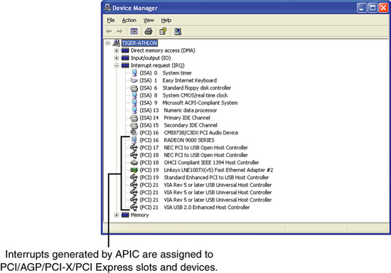
Note that APIC must be enabled in the system BIOS when Windows 2000 Server or Windows Server 2003 is installed to make APIC services available.
Note
The default view used by Device Manager in Windows 2000, Windows Server 2003, and client operating systems displays devices by type. To view IRQs and other hardware resources such as DMA, I/O port addresses, and memory addresses, select View, Resources by Type.
Linux Interrupt Handling
Linux handles PCI interrupts differently than Windows 2000 Server or Windows Server 2003. Linux does not assign IRQs to devices until they are actually used. To ensure that Linux has assigned IRQs to all onboard devices, you should use each onboard device as soon as Linux is installed.
To view Linux IRQ usage, you can use the command-line program cat/procs/interrupts. Each IRQ in use is listed by its IRQ number. Each IRQ number displays the type of interrupt controller used to generate the IRQ and the device that is using the IRQ.
Unlike Windows 2000 Server and Windows Server 2003, Linux is not designed to share IRQs. If two or more IRQs are listed as using the same IRQ when you run cat/procs/interrupts, you have an IRQ conflict unless the devices are using the same add-on card. To resolve the conflict, see the following tip.
Tip
To fix conflicts between cards on a modern x86 server that uses a PnP BIOS or operating system, try the following:
- Disable the BIOS setting for PnP operating system, particularly if you use Linux. If you use Windows 2000 Server or Windows Server 2003 and this setting is already disabled, try enabling it.
- Select the option to clear the Enhanced System Configuration Data (ESCD) settings in the BIOS and restart the system. The system will reconfigure PnP cards.
- If you have conflicts between cards in different slots or between cards and onboard devices, move one of the conflicting cards to a different slot.
- Disable unused legacy ports such as integrated parallel and serial ports. This can enable the BIOS to use the IRQs reserved for those ports for PCI and other non-legacy devices.
Recent Linux distributions also support APIC, enabling you to use PCI interrupts above 15, if APIC is enabled in the system BIOS. If APIC is enabled, each PCI device is likely to be assigned to its own IRQ, eliminating conflicts. Linux is not designed to support IRQ sharing, so the use of APIC on a Linux-based server is even more essential to avoid IRQ problems. Note that APIC is fully supported in Linux kernel v2.6 and higher.
The PCI bus enables two types of devices to exist: bus masters (initiators) and slaves (targets). A bus master is a device that can take control of the bus and initiate a transfer. The slave device is the intended destination of the transfer. Most PCI devices can act as both masters and slaves, and to be compliant with the PC'97 and newer system design guides, all PCI slots must support bus master cards.
The PCI bus is an arbitrated bus: A central arbiter (part of the PCI bus controller in the motherboard chipset) governs all bus transfers, giving fair and controlled access to all the devices on the bus. Before a master can use the bus, it must first request control from the central arbiter, and then it is granted control for only a specified maximum number of cycles. This arbitration allows equal and fair access to all the bus master devices, prevents a single device from hogging the bus, and prevents deadlocks because of simultaneous multiple device access. In this manner, the PCI bus acts much like a local area network (LAN), albeit one that is contained entirely within the system and runs at a much higher speed than conventional external networks between PCs.
DMA Channels
Communications devices that must send and receive information at high speeds use DMA channels. A serial port does not use a DMA channel, but an ISA-based SCSI adapter often does, as does a parallel port using ECP or EPP/ECP modes. DMA channels can sometimes be shared if the devices are not the type that would need them simultaneously. However, there is hardly any need to share DMA channels on a system that has no ISA or EISA slots.
Note
There are several types of DMA in a modern PC. The DMA channels referred to in this section involve the ISA bus. Other buses, such as the ATA/IDE bus used by hard drives, have different DMA uses. The DMA channels explained here don't involve your ATA/IDE drives, even if they are set to use DMA or Ultra DMA transfers.
Since the introduction of the 286 CPU, the ISA bus has supported eight DMA channels, with seven channels available to the expansion slots. Similar to the expanded IRQ lines described earlier in this chapter, the added DMA channels were created by cascading a second DMA controller to the first one. DMA channel 4 is used to cascade channels 0–3 to the microprocessor. Channels 0–3 are available for 8-bit transfers, and channels 5–7 are for 16-bit transfers only. Table 4.14 shows the typical uses for the DMA channels on a typical x86 or Itanium server.
Table 4.14 16-Bit ISA Default DMA Channel Assignments as Used on x86 and Itanium Servers
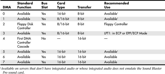
In Table 4.14, DMA channels 0, 1, and 5 would be assigned to audio if the server had an ISA sound card or a PCI sound card or integrated audio that emulates the Creative Labs Sound Blaster Pro. However, these DMA channels are listed as available because most servers do not have onboard or card-based audio.
I/O Port Addresses
A computer's I/O ports enable communications between devices and software in the system. They are equivalent to two-way radio channels. If you want to talk to the serial port, you need to know on which I/O port (radio channel) it is listening. Similarly, if you want to receive data from the serial port, you need to listen on the same channel on which it is transmitting.
Unlike IRQs and DMA channels, systems have an abundance of I/O ports. There are 65,535 ports to be exact—numbered from 0000h to FFFFh—which is an artifact of the Intel processor design more than anything else. Even though most devices use up to 8 ports for themselves, with that many to spare, you won't run out anytime soon. The biggest problem you have to worry about is setting two devices to use the same port. Most modern plug-and-play systems resolve any port conflicts and select alternative ports for one of the conflicting devices.
One confusing issue is that I/O ports are designated by hexadecimal addresses similar to memory addresses. They are not memory; they are ports. The difference is that when you send data to memory address 1000h, it gets stored in your SIMM or DIMM memory. If you send data to I/O port address 1000h, it gets sent out on the bus on that "channel," and anybody listening in could then "hear" it. If nobody is listening to that port address, the data reaches the end of the bus and is absorbed by the bus-terminating resistors.
Driver programs primarily interact with devices at the various port addresses. The driver must know which ports the device is using to work with it, and vice versa. That is not usually a problem because the driver and device come from the same company.
Motherboard and chipset devices are usually set to use I/O port addresses 0h–FFh, and all other devices use 100h–FFFFh. Table 4.15 shows the commonly used motherboard and chipset-based I/O port usage.
Table 4.15 Motherboard and Chipset-Based Device Port Addresses
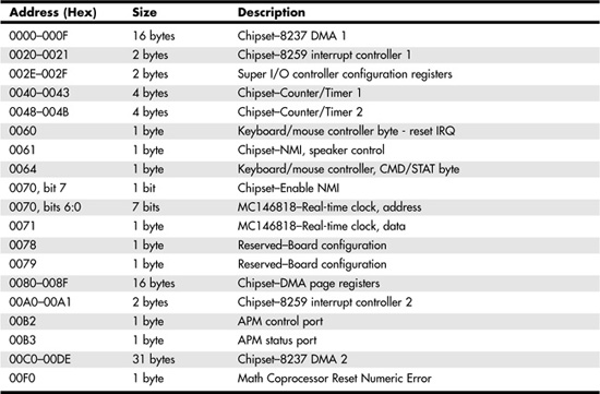
To find out exactly which port addresses are being used on your motherboard, consult the board documentation or look up the settings in the Windows Device Manager.
Bus-based devices typically use the addresses from 100h up. Table 4.16 lists the commonly used bus-based device addresses and some common adapter cards and their settings.
Table 4.16 Bus-Based Device Port Addresses
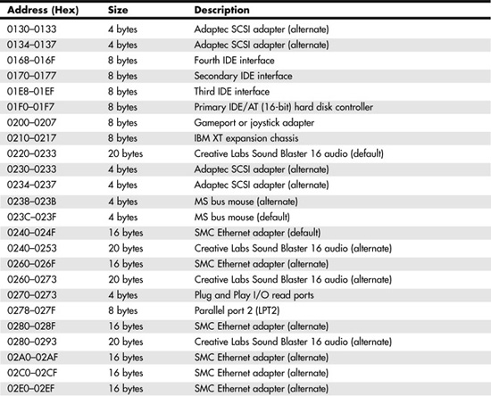
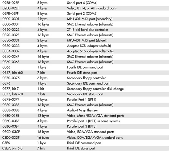

To find out exactly what your devices are using, you should consult the documentation for the device or look up the device in the Windows Device Manager. Note that the documentation for some devices might list only the starting address instead of the full range of I/O port addresses used.
Figure 4.35 shows a portion of the I/O port address map for a typical 32-bit Windows system. Note that some I/O port address ranges appear to have a conflict, such as 03B0–03FBB, which is used by the chipset's AGP controller and the installed video card (RADEON 9000). However, this is not a conflict but actually indicates that the I/O port address range is used to communicate between the devices listed.
Figure 4.35 A portion of a system's I/O port address, as displayed by the Windows Device Manager.
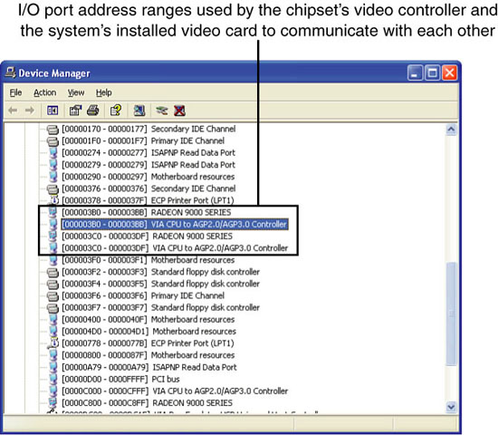
Virtually all devices on the system buses use I/O port addresses. Most of these are fairly standardized, which means conflicts or problems do not often occur with these settings.
Embedded and Integrated Components
There are a variety of connectors on a modern motherboard. Figure 4.36 shows connector locations on a typical motherboard. Note that Figure 4.36 combines features from several different motherboards; you might not see every feature on a particular motherboard. Several of these connectors, such as power supply connectors, serial and parallel ports, and keyboard/mouse connectors, are covered in other chapters.
Figure 4.36 Typical motherboard connectors on a dual-processor server.
This section provides figures and tables that show the configurations and pinouts of most of the other interface and I/O connectors you will find.
One of the biggest problems many people overlook when building and upgrading systems is the front panel connections. Connectors that don't match between the motherboard and chassis are one of the small but frustrating things that can be problematic in an otherwise smooth upgrade or system build. Unfortunately, there is no single standard in use for front panel connectors on servers. The de facto standard for front panel connections in servers is the SSI front panel I/O connector shown in Figure 4.37. Motherboards that fully adhere to one of the current SSI standards (CEB, EEB, and TEB) use this I/O connector. Note that this I/O connector is often located on the left edge of the motherboard, as viewed from the front, rather than on the front edge, as with many desktop motherboards.
Figure 4.37 Front panel connections specified by SSI server standards.
This is a much larger connector than the 10-pin keyed header defined by the "Intel Front Panel I/O Connectivity Guide" first developed in 2000 and followed by Intel and some other desktop PC makers. The SSI front panel connector supports additional LEDs used for system faults, activity and fault lights for up to two onboard NICs, temperature sensor, system ID, NMI, SMBus, and chassis intrusion. These features are very important for server management. Most current Intel server motherboards use the SSI connector.
Other major brands of server motherboards, however, use different connector standards, and sometimes a single brand of server uses more than one front panel connector standard on different models. See the manual for a particular server or server motherboard to determine the pinout and features supported.
Tip
If your server uses SATA drives connected to an add-on card rather than the motherboard's integrated host adapter, the front drive access light will not operate. This light is normally connected to pins 7 and 9 of the SSI front panel connections shown in Figure 4.37 or to the equivalent pins on servers that use a different front panel connection standard. To enable the HDD activity light to operate when SATA drives connected to an add-on card are in use, connect the HDD activity light to the SATA adapter card, if possible. See the documentation for your server's SATA host adapter card to determine whether the card has a connector for HDD activity lights.
To adapt the connectors in a chassis to those on a motherboard, in some cases you might need to change the connector ends by removing the terminals and reinserting them into different positions. For example, in a chassis that uses a 3-pin power LED connection and a motherboard with only a 2-pin connection, you have to remove one of the terminals, reinsert it into the middle position on the 3-pin connector, and then plug the connector in to the motherboard so that two pins are mated and the third empty position is hanging off the end of the connector. Fortunately, the terminals are easy to remove by merely lifting a latch on the side of the connector and then sliding the terminal and wire back out. When the terminal is inserted, the latch automatically grabs the terminal and locks it into position. To minimize the need to adapt connectors, you should use a chassis recommended by your server motherboard vendor.
Many server motherboards include front panel USB connectors, which are designed to be connected to front-mounted USB connectors in the chassis. The standard uses a single 10-pin keyed connector to provide two USB connections. The pinout of a standard dual USB motherboard header connector is shown in Figure 4.38 and Table 4.17.
Figure 4.38 Front panel dual-USB header connector configuration.
Table 4.17 Front Panel USB Header Connector Pinout

Many chassis includes multiple inline connectors for the dual-USB–to–front panel connection instead of a single keyed connector. An example of this is shown in Figure 4.39.
Figure 4.39 Front panel USB cable using multiple individual non-keyed connectors.
Using the multiple individual connectors shown in Figure 4.39, you would have to plug each individual connector in to the proper pin. Some internal chassis USB cables use two 5-pin inline connectors, in which case you just need to ensure that you don't put them on backward. You should consult your motherboard and chassis manual for more information if you are unsure about your particular connections.
Caution
If your chassis uses multiple individual non-keyed connections, you must be sure to connect them properly to the connector on the motherboard. If you connect them improperly, you can cause a short circuit to occur that can damage the motherboard or any USB peripherals you plug in to the front panel connectors. Higher-quality motherboards usually have self-healing fuses on the power signals, which can prevent damage if such a situation occurs. You might want to tape the cables together before inserting them to keep them in the right sequence.
Other miscellaneous connectors might appear on server motherboards as well; several are shown in Table 4.18–4.24.
Table 4.18 Battery Connector
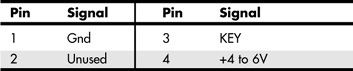
Table 4.19 LED and Keylock Connector
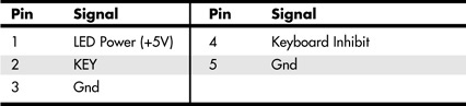
Table 4.20 Speaker Connector
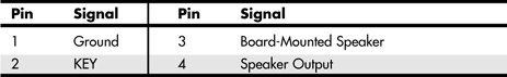
Table 4.21 Chassis Intrusion (Security) Pin-Header

Table 4.22 Wake on LAN Pin-Header
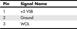
Table 4.23 Wake on Ring Pin-Header
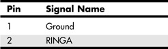
Table 4.24 SMB (I2C) Connector
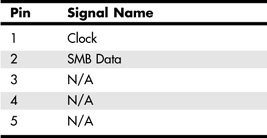
Most modern server motherboards have five or more fan connectors for use with the processor fan(s), rear chassis fan, front chassis fan, and voltage regulator (power) fan(s) (see Tables 4.25 and 4.26). They all generally use the same 3-pin connector, with the third pin providing a tachometer signal for optional speed monitoring. If the motherboard is capable of monitoring the fan speed, it can sound an alarm when the fans begin to slow down due to bearing failure or wear. The alarm sound can vary, but it normally comes from the internal speaker and might be an ambulance siren–type sound. Some systems use both 3-pin and 4-pin fan connectors; the extra pin provides support for pulse width modulation (PWM) fan speed control via the system BIOS, enabling the fan to run faster or slower, as needed, to provide adequate system cooling.
Table 4.25 Three-Pin Fan Power Connectors
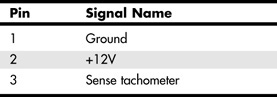
Table 4.26 Four-Pin Fan Power Connectors

Note that pins 1 through 3 of the 4-pin fan headers in Table 4.26 are the same as the pinouts in Table 4.25. Even though some motherboards have both types of fan headers (see Figure 4.36 for an example), you should use all the same type of fan if you enable thermal management control in the system BIOS.
Caution
Do not place a jumper on the fan connector; serious board damage will result if the 12V is shorted to ground.
SCSI, ATA/IDE, and SATA
Unlike desktop PCs, which use primarily ATA/IDE or SATA interfaces for hard disks, most servers use SCSI interfaces for hard disks, including RAID arrays. As a result, a typical server may feature one or two 68-pin SCSI connectors on the motherboard, with corresponding SCSI host adapter chips.
Servers use ATA/IDE host adapters primarily for optical (CD, DVD) drives. Depending on the chipset, ATA/IDE host adapters might run at typical UDMA speeds up to UDMA-100 or UDMA-133, or they might run at much slower PIO speeds.
Some recent servers use SATA ports in place of SCSI ports. In most cases, the SATA ports can be operated in a RAID 0 (striping) or RAID 1 (mirroring) configuration. If four SATA ports (and drives) can be connected to the motherboard, RAID 0+1 can be used for speed and safety. Some servers also support the new SAS (Serial Attached SCSI) standard, which supports both SAS and SATA drives.
The configuration of ATA/IDE and SATA host adapters on a server motherboard is performed through the system BIOS. Depending on the motherboard, SCSI and SAS host adapters might be enabled or disabled via the system BIOS or via jumpers on the motherboard. Note that the system or option BIOS is used to configure SATA or SCSI drives in a RAID array and to configure SCSI settings.
If SATA, SCSI, or SAS drives are supported by an add-on adapter, the adapter's BIOS is used to configure the interface and drives.
![]() For more information about ATA/IDE and SATA drives and interfaces, see Chapter 6, "The ATA/IDE Interface."
For more information about ATA/IDE and SATA drives and interfaces, see Chapter 6, "The ATA/IDE Interface."
![]() For more information about SCSI and SAS drives and interfaces, see Chapter 7, "The SCSI Bus."
For more information about SCSI and SAS drives and interfaces, see Chapter 7, "The SCSI Bus."
NICs, Modems, and Wireless NICs
Depending on the server, a network adapter (NIC) might be plugged in to a PCI, PCI-X, or PCI-Express x1 slot or might be located on the motherboard. Older servers with integrated NICs usually feature a 10/100 Ethernet RJ-45 port, while current servers with integrated NICs might feature a 10/100/1000 Ethernet RJ-45 port. Servers with two NIC ports can be used as routers without the addition of an additional NIC.
Although wireless networks using the IEEE 802.11 (Wi-Fi) family of standards are extremely common, there are virtually no servers with integrated wireless Ethernet NICs. Dial-up modems are also quite scarce on servers. Although servers designed for communications might feature one or more RJ-11 telephone jacks, these are normally used for connections to telephone switches rather than by analog modems.
Legacy Ports (Serial, Parallel, Keyboard, and Mouse)
Although legacy ports (serial, parallel, PS/2 keyboard, and PS/2 mouse) are fading away in current desktop and notebook computer designs, these ports are still virtually universal in server designs. There are several reasons for the continued popularity of legacy ports:
- Most KVM (keyboard, video, mouse) switches, which are often used to permit a single keyboard, mouse, and display to control multiple systems, support legacy ports plus VGA.
![]() For more information about KVM switches, see "KVM Switches," p. 497.
For more information about KVM switches, see "KVM Switches," p. 497.
- Serial ports enable a server to be controlled via an ASCII terminal or a Telnet connection from a remote PC.
- Parallel ports support dot-matrix and laser/LED printers for use in printing status reports.
Note that some server systems and motherboards omit the parallel port but usually include the other legacy ports listed here.
Servers that use ATX or other ATX-derived motherboard form factors provide access to legacy ports via the port cluster at the rear of the motherboard. PICMG-based single-board computers might place some legacy ports on the rear bracket, while others might be located on header cables. Although proprietary server designs vary in their legacy port locations, virtually all of them place the legacy ports at the rear of the system.
USB and IEEE 1394
USB ports are quite common on servers, but the level of USB support varies by server. Older servers might support USB 1.1 devices only, while most recent servers also support USB 2.0 devices.
If you plan to use USB input devices (mouse and keyboard), you need to be sure to verify that USB legacy support is available and enabled in the system BIOS. See "CMOS Settings and Specifications," later in this chapter, for details.
Although most recent and current servers support USB 2.0 devices, most servers do not support USB devices such as floppy or flash memory drivers as boot devices. If your system does not support USB drives as boot devices and you plan to use floppy disk–based diagnostic or testing software, you should specify a traditional floppy-controller–based 1.44MB floppy drive as part of your server's configuration or use bootable CD-based diagnostic and testing programs. To determine whether your server can boot from a USB drive, check the server's BIOS configuration.
Although USB ports are common on servers, the only servers that incorporate IEEE 1394 ports are Macintosh servers. Servers can use IEEE 1394 ports for high-speed external storage.