Chapter 6
Create and Deploy Virtual Machines and vApps
VCP5 Exam Objectives Covered in This Chapter:
- Create and Deploy Virtual Machines
- Identify capabilities of virtual machine hardware versions
- Configure and deploy a Guest OS into a new virtual machine
- Place Virtual Machines In Selected ESXi Hosts/Clusters/Resource Pools
- Identify methods to access and use a virtual machine console
- Install/Upgrade/Update VMware Tools
- Identify VMware Tools device drivers
- Configure virtual machine time synchronization
- Identify virtual machine storage resources
- Configure/Modify disk controller for virtual disks
- Configure appropriate virtual disk type for a virtual machine
- Create/Convert thin/thick provisioned virtual disks
- Configure disk shares
- Determine appropriate datastore locations for virtual machines based on application workloads
- Configure/Modify virtual CPU and Memory resources according to OS and application requirements
- Configure/Modify virtual NIC adapter and connect virtual machines to appropriate network resources
- Convert a physical machine using VMware Converter
- Import a supported virtual machine source using VMware Converter
- Modify virtual hardware settings using VMware Converter
- Create and Deploy vApps
- Determine when a tiered application should be deployed as a vApp
- Create a vApp
- Add objects to an existing vApp
- Identify and Edit vApp settings
- Configure IP pools
- Suspend/Resume a vApp
- Clone and Export a vApp
This chapter will cover the objectives of sections 4.1 and 4.2 of the VCP5 exam blueprint. It will focus on creating and deploying virtual machines and vApps.
This chapter will first cover identifying the capabilities of virtual machine hardware versions. Configuring and deploying a guest OS into a new VM will also be covered. Identifying methods to access the console of a VM will be covered. The chapter will cover how to install and upgrade VMware Tools and how to identify VMware Tools device drivers. Configuring VM time synchronization will be covered. It will cover how to identify VM storage resources and how to modify the disk controller for virtual disks. The chapter will also cover how to configure the appropriate virtual disk type for a virtual machine. Creating and converting thin and thick provisioned virtual disks and configuring disk shares will be covered. The chapter will also cover placing virtual machines in selected ESXi hosts, clusters, and resource pools.
The chapter will cover converting a physical machine (P2V) and importing a supported VM source using VMware Converter. Modifying VM hardware settings using VMware Converter will also be covered. It will also cover configuring and modifying vCPU and memory resources according to OS and application requirements, in addition to configuring and modifying virtual NIC adapters and connecting VMs to appropriate network resources. Determining appropriate datastore locations for virtual machines based on application workloads will also be discussed.
The final section of this chapter will cover determining when a tiered application should be deployed as a vApp. It will cover how to create, clone, and export vApps. Configuring IP pools for vApps will be covered, as well as editing vApp settings. The chapter will also cover how to add objects to an existing vApp and suspend and resume a vApp.
Creating and Deploying Virtual Machines
Everything covered thus far in this book has been about getting to this point. The virtual infrastructure exists in its entirety to run virtual machines. Knowing how to create and deploy VMs is an essential task for any virtual infrastructure administrator. The first topic covered is identifying the capabilities of virtual machine hardware versions.
Identifying Capabilities of Virtual Machine Hardware Versions
A virtual machine hardware version is used to designate the features of the virtual hardware. The virtual machine hardware version indicates the hardware features available in the virtual machine and can include things such as the BIOS or EFI, number of CPUs, maximum memory configuration, and more. When a virtual machine is created using the vSphere Client, you can use the Custom option to choose the version of the virtual machine hardware. By default, new virtual machines will be created with the latest version of the virtual hardware available on the host where the VM is being created. In vSphere 5, this will be virtual machine hardware version 8.
Virtual machine hardware version 8 includes the following capabilities:
- 32 vCPU support
- 1TB memory support
- Virtual NUMA (vNUMA) support
- Enhanced graphics, including 3D support
- USB 3.0 device support
- Client-connected USB devices
- EFI BIOS
- Smart card reader support
- Support for Mac OS X Server v10.6
The capabilities of virtual machine hardware version 8 are an improvement over the capabilities of virtual machine hardware version 7, which was included with vSphere 4. The capabilities of virtual machine hardware version 7 included support for eight vCPUs and 255GB memory. Comparing virtual machine hardware version 7 with virtual machine hardware version 4, which included support for four vCPUs and 64GB minus 4MB memory, makes it somewhat easier to see the evolution of the virtual machine hardware versions.
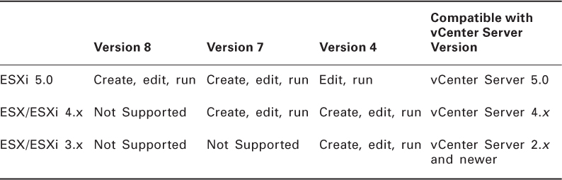
Virtual machines using virtual machine hardware versions prior to version 8 can still be run on ESXi 5 hosts but will not have all of the features of virtual machine hardware version 8. Table 6.1 shows the ESX/ESXi host and virtual hardware compatibility.
Table 6.1 ESX/ESXi Host and virtual hardware compatibility
If you want to use the latest features included in virtual machine hardware version 8, you must also use ESXi 5.

Virtual machine hardware versions can be upgraded; this process was covered in Chapter 2 of this book.
Now that I have covered the capabilities of virtual machine hardware versions, I will cover configuring and deploying a guest operating system into a new virtual machine.
Configuring and Deploying a Guest OS into a New Virtual Machine
There are two different ways to configure and deploy a virtual machine in vSphere 5. If you are familiar with vSphere 4, you will undoubtedly be comfortable with the process of configuring and deploying VMs from the vSphere Client, and with vSphere 5 this process is the same. Exercise 6.1 will cover configuring and deploying a new virtual machine.
Exercise 6.1: Configuring and Deploying a New VM with the vSphere Client
1. Connect to a vCenter Server with the vSphere Client.
2. Choose a datacenter, host, cluster, resource pool, or virtual machine folder and right-click it. Select the New Virtual Machine option from the context menu that appears.
3. The Create New Virtual Machine Wizard will launch.
4. Choose the Custom option in the Configuration section and click the Next button.
The Typical option can also be used here, but this will limit the number of choices you get to make when creating the VM. Specifically, one of the options that will be skipped is the virtual machine hardware version, which will default to the latest version supported on the ESXi host you deploy the VM to.
5. Give the virtual machine a unique name of up to 80 characters in length and specify an inventory location. Click the Next button to continue.
Additional information on initial virtual machine placement will be presented in the next section of this chapter.
6. If resource pools are configured on the destination host, choose a resource pool for the new VM and click the Next button. If resource pools are not configured on the destination host, then the wizard will simply skip this step.
7. Select a datastore that suits the workload requirements of the VM and that is large enough to hold the entire contents of the VM. Click the Next button to continue.
If you are using either VM storage profiles or Storage DRS, then there are additional options presented on this screen. If either of these options is appropriate for your environment, select them now. Storage DRS is covered in Chapter 8 of this book.
8. Keeping in mind the virtual machine hardware version compatibility listed in
Table 6.1, choose virtual machine hardware version 8. If there will be compatibility issues with virtual machine hardware version 8, choose virtual machine hardware version 7 instead. Click the Next button to continue.
9. Select the guest operating system of Microsoft MS-DOS, as shown here.
It is important to remember that the guest operating system that is selected here will impact the remaining choices presented in the Create New Virtual Machine Wizard. A simple demonstration of this will now be presented.
10. Click the Next button. Because MS-DOS supports only a single processor, the wizard will skip the CPU step of the wizard and go straight to the Memory step. Take note of the prepopulated Memory Size field value here.
11. Click the Back button. Change the Guest Operating System Version to Microsoft Windows Server 2008 R2 (64-bit) and then click the Next button.
12. Because Windows 2008 Server R2 supports multiple processors, you will now be presented with the option to select the number of virtual sockets and the number of cores per virtual socket. Leave both of these values at the default of 1 and click the Next button to continue.
13. On the Memory screen, note that the prepopulated memory size value has been changed to reflect the VMware-recommended value specific to this guest OS. Again, accept the default value and click the Next button.
14. Choose the number of NICs that this virtual machine will have and assign them to the appropriate network. Also, use the drop-down menus to choose the appropriate network, adapter type, and whether the adapter will be in a connected state at power on. In the image shown here, the VM is assigned a single VMXNET3 adapter that will be connected to the VM Network (dvSwitch) at power on.
15. After the networking for the virtual machine has been configured, choose the SCSI controller to use for the virtual machine. Unless you have a specific use case, use the default selected controller. Click the Next button to continue.
The virtual network adapters and the SCSI controllers in the previous two steps will be discussed in detail later in this chapter.
16. Choose the Create A New Disk option and click the Next button. Note that there are options available to use an existing disk or to omit the disk entirely.
17. Provide the capacity for the new virtual disk using the options at the top of the screen. Select the Thin Provision option for Disk Provisioning, and use the Store With The Virtual Machine option for Location.
It is important to coordinate the virtual disk sizing with the datastore selected in step 7 earlier in this exercise. If you attempt to create a 200GB virtual disk on a datastore with 100GB of free space, you will receive an error. The disk provisioning options will be discussed later in this chapter.
18. After the virtual disk has been sized, click the Next button.
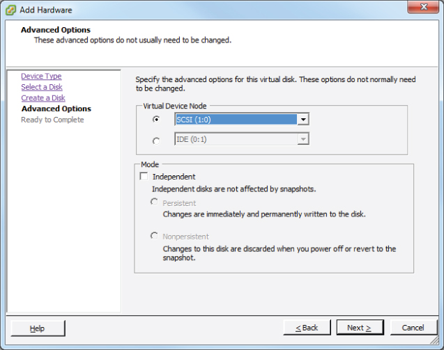
19. Accept the default value of SCSI 0:0 for Virtual Device Node and leave the Independent Mode option unchecked.
The Virtual Device Node setting identifies which SCSI controller will be used. In step 15 of this exercise, a controller type was selected. The disk you created in steps 16–17 will be attached to this controller as the first disk.
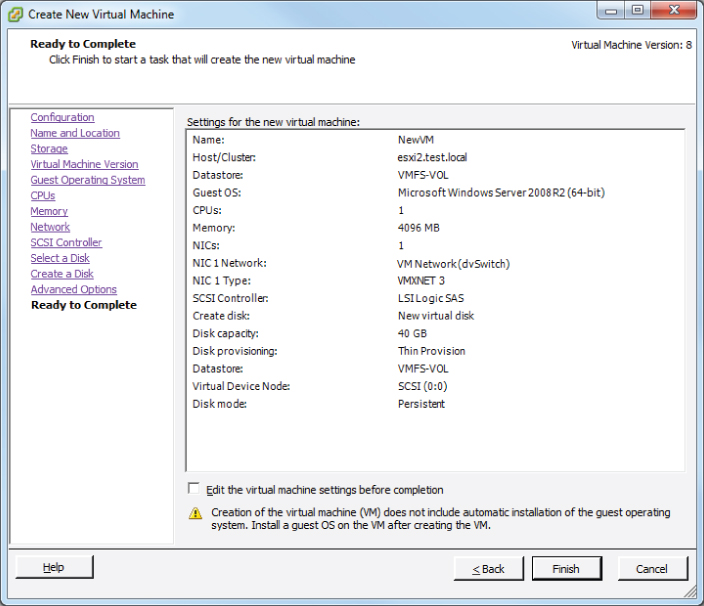
20. Click the Next button to continue and review the information presented in the Ready To Complete screen.
21. Take note of the Edit Virtual Machine Settings Before Completion option, which if checked will allow you to make additional changes to the VM's settings before creating the VM. Omit this option for now.
Also take note of the informational text at the bottom of the screen. This is a reminder that the Create New Virtual Machine Wizard will not install a guest operating system into the virtual machine. The guest OS must be installed, as a separate process just like with a physical machine, after the VM is created.
22. Click the Finish button to begin creating the new VM. A Create Virtual Machine task will begin. When it completes, the new VM will be listed in the inventory.

Virtual machines that use the EFI firmware have a minimum RAM requirement of 96MB, or they will not stay powered on.
I have now covered configuring and deploying a new VM with the vSphere Client. The other method for deploying a new VM in vSphere 5 is to use the vSphere Web Client. Exercise 6.2 will cover deploying a new virtual machine with the vSphere Web Client.
Exercise 6.2: Configuring and Deploying a New VM with the vSphere Web Client
1. Open a web browser and connect to the FQDN of the vCenter Server that will be used for this exercise.
2. Click the blue Log In To vSphere Web Client link.
3. When the vSphere Web Client loads, enter your credentials. These can be the same credentials used in the vSphere Client.
4. Choose a datacenter, host, cluster, resource pool, or virtual machine folder in the left pane. In the upper-right margin of the right pane, look for two icons. One is blue with a small green plus sign, and the other is a gray gear with a downward-facing arrow beside it.
5. Click the blue icon with the small green plus sign or click the gear and choose the Create Virtual Machine option from the Inventory menu. This will launch the Provision Virtual Machine Wizard.
6. Highlight the Create A New Virtual Machine option in the center of the screen by clicking it and then click the Next button to continue.
7. Give the virtual machine a unique name of up to 80 characters in length and specify an inventory location.
8. Select a folder or datacenter where the VM will be located. You can also search for the folder or datacenter using the provided search function. Click the Next button to continue.
Additional information on initial virtual machine placement will be presented in the next section of this chapter.
9. Select a cluster, ESXi host, vApp, or resource pool that will provide resources to this virtual machine. Click the Next button to continue.
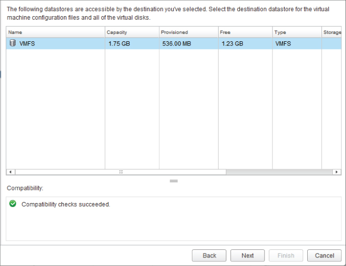
10. Select a datastore that suits the workload requirements of the VM and that is large enough to hold the entire contents of the VM. Ensure that the green circular icon with an arrow (compatibility check) is present at the bottom of the screen before continuing.
11. Click the Next button to continue.
12. Keeping in mind the virtual machine hardware version compatibility listed in
Table 6.1, choose virtual machine hardware version 8. If there will be compatibility issues with virtual machine hardware version 8, choose virtual machine hardware version 7 instead. Click the Next button to continue.
13. Choose Guest OS Family of Windows and Guest OS Version of Microsoft Windows Server 2008 R2 (64-bit) and click the Next button to continue.
14. On the Customize Hardware screen, review the settings for this new virtual machine. The settings will appear similar to what's shown here.
15. Use the drop-down menus to change the value for the New Network field and ensure that a check mark appears in the Connect box.
16. Click the right-pointing gray arrow that is located beside the New Hard Disk option to expand the new hard disk options. Locate the Disk Provisioning field in the left pane and then select the Allocate And Commit Space On Demand (Thin Provisioning) check box. The result should look like this.
After the thin provisioning has been selected, take a few moments to explore the rest of the disk options. Also, take some time to explore the remaining screens and view the available options in the vSphere Web Client. Note that both a Virtual Hardware view and a VM Options view are available, and these views can be toggled using the buttons at the top of the screen.
17. After reviewing the options in the Customize Hardware portion of the wizard, click the Next button to continue configuring and deploying this virtual machine.
18. You will be presented with the Review Settings screen. Verify the information presented here is correct and click the Finish button to deploy the new VM.
19. A Notification window will appear in the lower-right corner reporting a task in progress. A Create New Virtual Machine task will also appear in the Recent Tasks list in the vSphere Client.
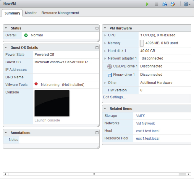
20. When the VM has been deployed, the vSphere Web Client view will refresh to show the new virtual machine.
21. Review the virtual machine settings in the vSphere Web Client for accuracy. Leave the vSphere Web Client open, because it will be used in the next exercise.
Just like with the vSphere Client, deploying a VM will not install an operating system on the VM. Use the same procedures for installing an OS that you would use for physical hardware.
I have now covered configuring and deploying a new virtual machine in the vSphere Client and the vSphere Web Client. In the next section, I will discuss in more detail the placement of virtual machines.
Placing Virtual Machines in Selected ESXi Hosts/Clusters/Resource Pools
When the virtual machines were created in Exercises 6.3 and 6.4, part of the process was to identify the inventory location. Figure 6.1 shows this step when using the vSphere Web Client.
The cluster, ESXi host, and resource pool can each be selected when the virtual machine is created. The available options will depend on how the virtual infrastructure is designed. For example, a cluster without DRS enabled will not have the resource pools as an option. The decision you make for the initial placement is in no way permanent, and virtual machines can move about the virtual infrastructure either through manual processes such as vMotion or through automated migrations from DRS.
Now that I have shown how to build virtual machines and discussed the options for their initial placement, I will cover identifying the methods used to access a virtual machine console.
Identifying Methods to Access and Use a Virtual Machine Console
Unlike physical machines, virtual machines don't have a keyboard, monitor, and mouse that an individual can physically sit down in front of and use to manage the VM. However, the virtual machine console can still be accessed. Several methods can be used to access virtual machine consoles. Applications such as Remote Desktop (RDP) and VNC can be used to access consoles, and vSphere also includes two built-in options. The vSphere Client and the vSphere Web Client both include the ability to access a virtual machine console.
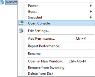
To access the virtual machine console from the vSphere Client, simply right-click any virtual machine in the inventory and choose the Open Console option from the context menu that appears, as shown in Figure 6.2.
The vSphere Web Client can also be used to access a virtual machine console, but the process is a bit more detailed. Exercise 6.3 will cover the steps required to access a virtual machine console using the vSphere Web Client.
Exercise 6.3: Accessing a Virtual Machine Console with the vSphere Web Client
1. Open a web browser and connect to the FQDN of the vCenter Server that will be used for this exercise.
2. Click the blue Log In To vSphere Web Client link.
3. When the vSphere Web Client loads, click Download Client Installation Plug-in located in the bottom-left corner of the screen.
4. Use the procedure appropriate for your web browser to launch the VMware Remote Console Plug-in application.
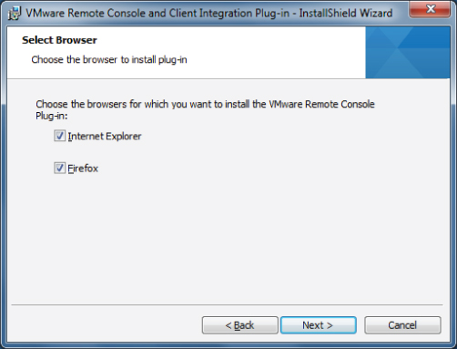
5. When the VMware Remote Console Application launches, click the Next button to begin. Select the boxes for the web browsers on which you want to install the plug-in.
6. You may be prompted to close your web browser(s) before continuing. Click the Install button to begin the installation of the VMware Remote Console Application.
7. Click the Finish button when the installation completes. Open your web browser and return to the vSphere Web Client login screen.
8. After logging in, expand the objects in the left pane and locate a virtual machine. Select a virtual machine in the left pane by clicking it.
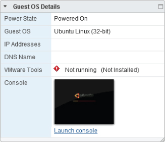
9. In the center of the screen in the Guest OS Details pane, click the blue Launch Console link.
10. The Console window will open in a new tab in the browser window.
For working in the console window, using the vSphere Web Client, here are some helpful commands:
- Pressing Ctrl+Alt will release the cursor from the console window.
- Pressing Ctrl+Alt+Enter will exit full screen mode.
Now that I have covered identifying the various methods used to access virtual machine consoles, you can turn your attention to installing, upgrading, and updating the VMware Tools.
Installing, Upgrading, and Updating VMware Tools
Although never required for guest OS functionality, VMware Tools enhance the performance of a VM's guest operating system and provide additional management functionalities for the VM. VMware Tools can be installed manually using the vSphere Client, and the procedure will be covered in Exercise 6.4 for a Windows guest operating system.
Exercise 6.4: Installing VMware Tools Using the vSphere Client
1. Open a console session to a virtual machine.
2. From the VM menu option, choose the Guest submenu and then select the Install/Upgrade VMware Tools option.
3. An Install VMware Tools dialog will be presented. Review this information and click the OK button to continue.
4. The CD-ROM image will be mounted, and if enabled, autorun.exe will launch Setup. If autorun.exe does not begin installation, browse the contents of the mounted CD-ROM and start the installation manually.
5. Click the Next button on the VMware Tools Welcome screen.
6. Choose the Custom option and click the Next button to continue.
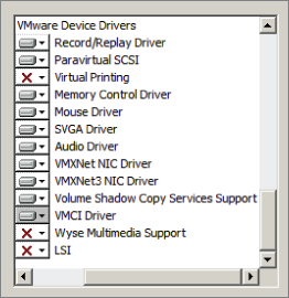
7. In the left pane, expand the VMware Device Drivers and review the list of device drivers that will be installed. The complete list of device drivers is shown here.
8. Note that the installation directory can be changed by using the Change button. Click the Next button to continue.
9. Click the Install button to install the VMware Tools.
10. When the installation is complete, click the Finish button. You will then be prompted to reboot the guest OS. Click the Yes button to reboot the VM now.
Now that I have covered installing VMware Tools in a virtual machine, I will cover upgrading and updating the VMware Tools. Upgrading and updating the VMware Tools is likely also a familiar process for most virtual infrastructure administrators, because it is a VMware-recommended best practice to keep the VMware Tools at the latest release available.
As mentioned in Chapter 2, VMware Tools can be upgraded manually, or virtual machines can be configured to check and upgrade automatically during power cycling of the VM. Update Manager is another option for upgrading the VMware Tools. An interesting fact is that the upgrade is actually an uninstall of the old VMware Tools followed immediately by an install of the latest version of the VMware Tools. Exercise 6.5 will cover the steps for upgrading an existing VMware Tools installation on Windows Server 2008 R2 to the latest version.
Exercise 6.5: Upgrading VMware Tools Using the vSphere Client
1. Open a console session to a virtual machine.
2. From the VM menu option, choose the Guest submenu and then select the Install/Upgrade VMware Tools option.
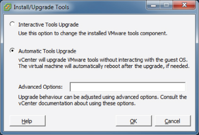
3. An Install/Upgrade Tools dialog will appear.
4. Choose the Automatic Tools Upgrade option and click the OK button.
The Automatic Tools Upgrade option will uninstall the old VMware Tools, install the new version of the VMware Tools with no interaction, and then reboot the guest OS if necessary.

When choosing the Automatic Tools Upgrade option, if a reboot is required, it will happen without prompting. Be sure to remember this when choosing the option you will use to upgrade the VMware Tools.
One other option that is occasionally required is to update the VMware Tools. This can be useful in situations where a particular device driver needs to be added or removed from the installation. The process for updating the VMware Tools is nearly identical to the upgrade process. The difference will be covered in Exercise 6.6, where the steps to remove Virtual Printing will be covered.
Exercise 6.6: Updating VMware Tools Using the vSphere Client
1. Open a console session to a virtual machine.
2. From the VM menu option, choose the Guest submenu and then select the Install/Upgrade VMware Tools option.
3. An Install/Upgrade Tools dialog will be presented.
4. Choose the Interactive Tools Upgrade option and click the OK button.
5. The CD-ROM image will be mounted, and if enabled, autorun.exe will launch Setup. If autorun.exe does not begin installation, browse the contents of the mounted CD-ROM and start the installation manually.
6. The VMware Tools installer will launch. Click the Next button on the Welcome screen to begin.
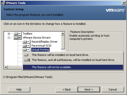
7. Choose the Modify option and click the Next button to continue.
8. In the left pane, expand the VMware Device Drivers item and locate Virtual Printing. Select Virtual Printing and choose This Feature Will Not Be Available, as shown here.
9. The Virtual Printing icon will now have a red X to its left. Click the Next button to continue.
10. Click the Modify button to begin the update of the VMware Tools.
11. Click the Finish button when the update completes and click the Yes button on the restart prompt.
The version of VMware Tools included with vSphere 5 is supported on both vSphere 4.x and vSphere 5 virtual machines. The version of VMware Tools included with vSphere 4.x is also supported in vSphere 5.
I have now covered installing, upgrading, and updating the VMware Tools. In the next section, I will cover the device drivers that are included with the VMware Tools.
Identifying VMware Tools Device Drivers
The VMware Tools provide device drivers for the mouse, sound, graphics, networking, and more, but the device drivers that are installed in a typical VMware Tools installation will depend on the guest operating system. Performing a custom installation of VMware Tools, or a modify operation of an existing installation, will allow you to choose which device drivers are installed in the guest OS. Table 6.2 lists the VMware Tools device drivers that could be included in a VMware Tools installation and a brief description of each.
Table 6.2 VMware Tools device drivers
| Record/Replay |
Used to enable recording and replaying of virtual machines. |
| Paravirtual SCSI |
Used to provide increased performance for paravirtualized SCSI devices. |
| Virtual Printing |
Used to allow guests to access the host's printers. |
| Memory Control |
Used to provide enhanced memory management functionality. |
| Mouse |
Used to smooth mouse movement in the guest OS. |
| SVGA |
Used to enable 32-bit displays, greater display resolutions, and improved graphics performance. |
| Audio |
Used to provide audio for virtual sound cards. |
| SCSI |
Used when the BusLogic adapter is specified for a virtual machine. |
| VMXNet NIC |
Used to provide increased performance for network devices. |
| Volume Shadow Copy Service Support |
Used to enable VSS support for Windows Vista or Windows Server 2003 or newer. Older versions of Windows will use the FileSystem Sync driver instead. |
| VMCI |
Used to enable VM-to-VM or VM-to-host communications using datagrams and shared memory. |
| Wyse Multimedia Support |
Used to enhance remote desktop multimedia experience. |
| LSI |
Used to provide enhanced drivers for LSI controllers. |
Windows Vista and newer guest operating systems will use the VMware SVGA 3D (Microsoft – WDDM) driver, instead of the SVGA driver. This driver is used to add support for Windows Aero.
Now that I have covered the VMware Tools device drivers, I will move on to configuring virtual machine time synchronization.
Configuring Virtual Machine Time Synchronization
The VMware Tools have the ability to synchronize the time of the guest OS with the time of the ESXi host that the guest is running on. This feature is known as periodic time synchronization. When this feature is enabled, VMware Tools will check once a minute to determine whether the clocks are synchronized. If the clocks are not in sync, the time will be adjusted in the guest OS accordingly. The VMware Tools will move the time ahead for guests that have fallen behind and will slow down the clock on guests that have become ahead of the current host time.
In most cases, the native functions (Win32Time, NTP) used in operating systems will be more accurate than periodic time synchronization and should be used instead to guarantee accurate time in the guest OS. Regardless of the approach taken, only a single method of time synchronization should ever be used.
Exercise 6.7 will cover the steps used to determine whether VMware Tools periodic time synchronization is in use. I will also cover how to enable and disable periodic time synchronization. This exercise will use a Windows Server 2008 R2 guest OS and will use the command-line tools. As a reminder, vSphere 5 will be the final vSphere release to support the VMware Tools GUI.
Exercise 6.7: Configuring Periodic Time Synchronization in a Virtual Machine
1. Obtain a console session to a virtual machine with a Windows 2008 R2 guest OS and log in.
2. Open a command prompt and type the following command:
cd “C:Program FilesVMwareVMware Tools”
Note that on different Windows operating systems, this path may vary. On Linux and Solaris the path will be /usr/sbin and will vary on other operating systems as well.
3. At the command prompt, type the following command:
VmwareToolboxCmd.exe timesync status
Note that on Linux, Solaris, and FreeBSD the command is as follows:
vmware-toolbox-cmd
4. The results of this command are shown here.
5. In this example, time synchronization is disabled. To enable time synchronization, the following command would be entered:
VmwareToolboxCmd.exe timesync enable
6. If time synchronization is disabled, the following command would be entered to enable it:
VmwareToolboxCmd.exe timesync disable
At this point, periodic time synchronization has been disabled. Certain operations will trigger the VMware Tools to synchronize time in the virtual machine:
- Starting VMware Tools service/daemon (reboot or power on)
- Resuming a VM from a suspend operation
- Reverting to snapshot
- Shrinking a disk
To completely disable all VMware Tools–initiated time synchronization functionality for a VM, the virtual machine's .vmx file must be modified.
Now that I have covered time synchronization, I will cover identifying virtual machine storage resources.
Identifying Virtual Machine Storage Resources
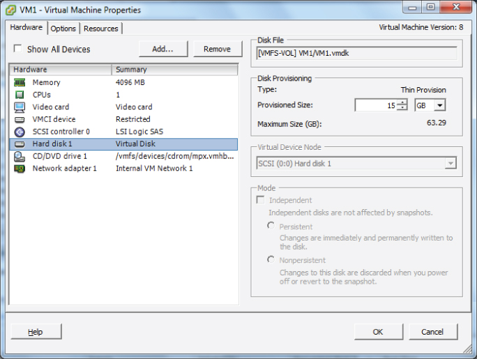
In Exercise 6.1 you configured and deployed a virtual machine. Part of the configuration was the creation of a virtual disk for the virtual machine. Now that the VM has been deployed, I will identify its storage resources. Figure 6.3 shows the storage resources used by a virtual machine.
Four areas are listed for the selected storage resource. The first field is Disk File and shows the path information of the virtual disk. The Disk File field includes the datastore, the VM directory name, and the virtual disk name.
The second area listed is Disk Provisioning. The Type value is listed first in the Disk Provisioning area and shows the disk format used by the virtual disk. The next item listed in the Disk Provisioning area is Provisioned Size. This shows the amount of disk space provisioned for the virtual disk. The final item listed is the Maximum Size (GB) value, which represents the maximum size the VMDK file can grow to.
The third area is Virtual Device Node. This represents the SCSI controller and the drive number. In Figure 6.3, SCSI 0:0 is used, meaning SCSI controller 0 and disk 0. Note that this value is grayed out for powered-on virtual machines.
The final area is Mode. This is where independent disks can be configured. As with the virtual device node, the disk mode field is also grayed out for powered-on virtual machines. Independent disks are excluded from snapshot operations. Two modes can be used with independent disks:
Independent Persistent This disk behaves just like a normal disk, and all writes are committed to disk.
Independent Nonpersistent All changes to this type of independent disk are lost at VM power off or reset.
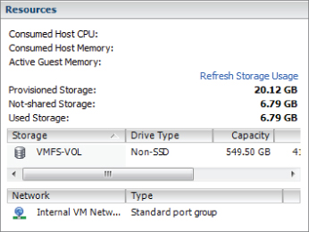
There is one other location to obtain information about virtual machine storage resources. In the Resources panel on the Summary tab for the virtual machine there are three fields, as shown in Figure 6.4.
The storage resource information presented here consists of the following:
Provisioned Storage This value represents the provisioned size of all virtual disks in the virtual machine plus the size of the virtual machine's swap file.
Not-shared Storage This is the amount of storage used only by the VM and not shared with other VMs.
Used Storage This is the amount of space consumed by all of the files that make up the virtual machine, including swap files, config files, and snapshots. For thin provisioned disks, this value will typically report a value less than the value reported for the Provisioned Storage field.
Now that I have covered identifying virtual machine storage resources, I will cover configuring and modifying disk controllers for virtual disks.
Configuring and Modifying Disk Controller for Virtual Disks
Virtual SCSI controllers are used by virtual machines to access their virtual disks. When you create a virtual machine, the default controller for the guest operating system you selected will be provided. This controller type will seldom need to be changed. The virtual SCSI controller types are described here:
BusLogic Parallel This is an emulated version of a hardware storage adapter from BusLogic. This adapter is typically used with older operating systems that include the BusLogic driver by default.
LSI Logic Parallel This is an emulated version of a hardware storage adapter from LSI. This adapter is typically used with newer operating systems that include the LSI driver by default.
LSI Logic SAS This controller was introduced with vSphere 4 and is intended to provide increased performance over the BusLogic and LSI Logic Parallel controllers. It is available only for VMs that are using virtual machine hardware version 7 or newer. As some vendors phase out support for parallel SCSI, the LSI Logic SAS adapter could also be a wise choice to ensure future compatibility. Check with your OS vendor for more information.
VMware Paravirtual This storage controller was also introduced with vSphere 4 and is intended to provide high performance with lower CPU utilization. It is intended for use with high I/O and high-performance storage and is not supported by all operating systems. Check the following VMware KB article to ensure operating system compatibility with the VMware Paravirtual SCSI (PVSCSI) adapter:
http://kb.vmware.com/kb/1010398
Virtual disks cannot be reassigned to a different controller type.
In addition to specifying the disk controller type, you can also configure the SCSI bus sharing type to be used with the controller. SCSI bus sharing allows different virtual machines to access the same virtual disk(s) simultaneously and is useful in clustering solutions. The three types of SCSI bus sharing are as follows:
None This is the default setting and does not allow the virtual disks to be shared.
Virtual This setting allows virtual disks to be shared by virtual machines located on the same ESXi host.
Physical This setting allows virtual disks to be shared by virtual machines located on any ESXi host.
The available operations for SCSI controllers are adding, removing, and changing the type, as well as setting the bus sharing options. In Exercise 6.8 you will add an additional disk controller and configure the SCSI bus sharing options for it. The exercise will begin with a Windows 2008 R2 guest OS on a virtual machine with a single LSI Logic SAS controller and virtual disk.
Exercise 6.8: Configuring and Modifying a Disk Controller in the vSphere Client
1. Connect to a vCenter Server with the vSphere Client.
2. Right-click a powered-off virtual machine from the inventory. Choose the Edit Settings option from the context menu that appears.
3. The Virtual Machine Properties editor will appear, as shown here.
The first step is to add an additional controller to the virtual machine.
4. Click the Add button located at the top of the Hardware tab. The Add Hardware window will appear. Select Hard Disk from the list of devices in the middle of the screen and click the Next button to continue.
5. On the Select A Disk screen, choose the Create A New Virtual Disk option and click the Next button.
6. Give the disk a capacity of 1GB and choose the Thick Provision option for Disk Provisioning. Click the Next button to continue.
7. On the Advanced Options screen, use the drop-down menu to change Virtual Device Node to 1:0, as shown here.
Choosing virtual device node 1:0 will create a new virtual disk controller, since the default disk added to the VM upon creation is typically on virtual device node 0:0.
8. Click the Next button to continue. On the Ready To Complete screen, click the Finish button.
9. Notice that in the Virtual Machine Properties window, there are new bold entries for the controller and disk you just added. Select the New SCSI Controller (Adding) item.
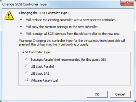
10. Note the SCSI Controller Type listed in the top right of this screen. Click the Change Type button.
11. A Change SCSI Controller Type window will appear.
12. Review the warning information presented before proceeding.
13. Change the SCSI Controller Type option to VMware Paravirtual and click the OK button.
14. Now notice that in the Virtual Machine Properties window, the LSI Logic SAS controller has been changed to Paravirtual.
At this point, the disk controller has been changed, but you still need to change the SCSI Bus Sharing options. The remainder of this exercise will cover the steps required to change the SCSI Bus Sharing options.
15. In the Virtual Machine Properties window, click the Virtual option listed under SCSI Bus Sharing.
16. Click the OK button to save the changes.
17. A Reconfigure Virtual Machine task will start. When this task completes, the virtual machine is ready to be powered on and used.
Disk controllers can also be added, removed, modified, and have their SCSI bus sharing options changed using the vSphere Web Client.
Now that I have covered configuring and modifying a disk controller, I will move on to showing how to configure the appropriate virtual disk type for a virtual machine.
Configuring Appropriate Virtual Disk Type for a Virtual Machine
As you saw in Exercise 6.8, when virtual disks are created, certain properties can be specified. These properties include the size of the disk, the type of provisioning to use, the location to store the disk, the virtual device node, and the disk mode. In this section, the different virtual disk types will be discussed.
Virtual disk types, disk provisioning, and format are all used to refer to the type of virtual disk used in a virtual machine. The three types of virtual disks are flat disk, thick provision, and thin provision.
A flat disk, which is also known as a Thick Provision Lazy Zeroed disk, is a VMDK file that is created and all of the space is provisioned immediately. While the space is provisioned immediately, the space is actually zeroed on command. A virtual disk that is created as 20GB will consume 20GB of space on the datastore, regardless of the actual disk usage in the guest OS.
Zeroed or zeroing is the process where disk blocks are overwritten with zeroes. This process is performed to ensure that no prior data is still on the volume that might cause problems with the VMDK.
A thick provisioned disk, which can also be known as a Thick Provision Eager Zeroed disk, is a VMDK file that is created and all of the space is provisioned immediately. With this type of VMDK, the space is also zeroed at the time of creation. This type of disk takes the longest to create and is required for certain features like VMware FT. A virtual disk that is created as 20GB will consume 20GB of space on the datastore, regardless of the actual disk usage in the guest OS. There is a slight performance increase with this format, since the zeroing does not have to happen at runtime like it does with the other two formats.
A thin provisioned disk is a VMDK file that is created with a zero size, and it will grow on demand as required. A virtual disk that is 20GB will consume approximately the actual space used by the guest operating system.
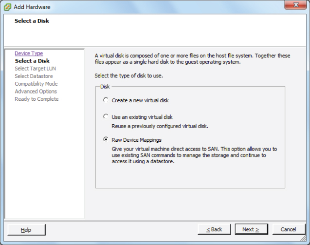
In addition to virtual disks, raw device mappings can be used in virtual machines. A raw device mapping (RDM) file can be used to store virtual machine data directly on the SAN, as opposed to storing it in a VMDK file on a VMFS datastore. This can be useful if SAN snapshots are required, if applications that are SAN aware are used, or if Microsoft Cluster Service (MSCS) is used.
Adding an RDM to a virtual machine will create an RDM file that points to the raw device. This RDM file will have a .vmdk extension and will even report the size of the raw device in the Datastore Browser, but this file contains only the mapping information. Two compatibility modes can be used with RDMs:
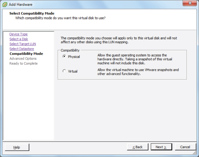
Physical This compatibility mode allows the guest OS to access the raw device directly and is used for SAN-aware applications running in a virtual machine. Snapshots are not possible with this compatibility mode.
Virtual This compatibility mode allows the guest OS to treat the RDM more like a virtual disk and can be used with snapshots.
In Exercise 6.9, I will cover the steps to add an RDM to a virtual machine using the vSphere Client. Note that for this exercise you will need to have a raw device configured on your SAN.
Exercise 6.9: Adding an RDM to a Virtual Machine with the vSphere Client
1. Connect to a vCenter Server with the vSphere Client.
2. Right-click a virtual machine in the inventory. Choose the Edit Settings option from the context menu that appears.
3. The Virtual Machine Properties window will appear.
4. Click the Add button located at the top of the Hardware tab. The Add Hardware window will appear. Select Hard Disk from the list of devices in the middle of the screen and click the Next button to continue.
5. On the Select A Disk screen, choose the Raw Device Mappings option and click the Next button.
Note that if no applicable storage devices are available, the Raw Device Mappings option will be grayed out and unavailable.
6. Choose the LUN to use by selecting it from the list and click the Next button.
7. Select the default Store With Virtual Machine option and click the Next button.
8. Select the Compatibility Mode for the RDM and click the Next button.
9. Review the Virtual Device Node information and modify it if necessary. Click the Next button.
10. Review the information on the Ready To Complete screen and click the Finish button to add the RDM to the virtual machine.
11. Verify that New Hard Disk is listed and reported as Mapped Raw LUN in the Summary column.
12. Click the OK button on the Virtual Machine Properties window. A Reconfigure Virtual Machine task will begin. When this task completes, the RDM has been added.
13. To configure the RDM, use the native disk management tools in the guest OS to scan for new devices and to format the disk appropriately.
When configuring an RDM disk in the guest OS, make sure that the partition is aligned properly.
Configuring the appropriate virtual disk type for a virtual machine will depend on a variety of factors in your environment. Some of these factors could include the following:
Storage Consumption If space or the ability to over-allocate storage is a primary concern in an environment, then thin provisioned disks would be appropriate.
Fault Tolerance (FT) If VMware FT is required, then thick provisioned disks would be appropriate.
Performance If absolute performance is a concern, then thick provisioned disks would also be appropriate.
Storage Support If your storage is NFS and doesn't support the VAAI NAS extensions, then thin provisioning would be the only option.
Clustering Clustering solutions will often require thick provisioned disks and/or RDMs.
Disk Operations While all VMs are encapsulated and generally very portable, RDMs can be easily moved or attached to other virtual or physical servers in the same SAN fabric.
Now that I have covered configuring appropriate virtual disk types for virtual machines, I will cover creating and converting both thin and thick virtual disks.
Creating and Converting Thin/Thick Provisioned Virtual Disks
As you have seen in previous exercises, the virtual disk formats are typically chosen upon virtual machine creation. The format chosen here is in no way permanent, and the conversion of any disk format to another disk format is easily accomplished. Exercise 6.10 will cover the steps to convert a thin disk, in a powered-off virtual machine, to a thick disk.
Exercise 6.10: Converting a Thin Disk to a Thick Disk
1. Connect to a vCenter Server with the vSphere Client.
2. Select a powered-off virtual machine with a thin provisioned disk from the inventory. You created one of these in Exercise 6.1.
3. Right-click the virtual machine and choose the Edit Settings option from the context menu that appears.
4. When the Virtual Machine Properties window appears, select the hard disk from the list of devices.
5. In the right side of the Virtual Machine Properties window, verify that the Disk Provisioning Type value is reported as Thin Provision.
6. Also note the path to the virtual disk, as shown in the Disk File field at the top right of the Virtual Machine Properties window.
7. Click the Cancel button to exit the Virtual Machine Properties window.
8. Select the Summary tab for this virtual machine, and locate the datastore that houses this virtual machine's virtual disk in the Resources panel under the Storage listing.
9. Right-click the datastore and choose the Browse Datastore option that appears in the context menu.
10. The Datastore Browser will open. Navigate into the directory that is named the same as the VM.
11. Inside this directory, locate the virtual disk file using the path information obtained in step 6. Note the reported values for the virtual disk in both the Size and Provisioned Size columns.
12. Right-click the virtual disk file and choose the Inflate option from the context menu that appears, as shown here.
13. An Inflating window will appear that provides the progress of the inflate operation. This task may take some time to complete for large VMDK files. An Inflate Virtual Disk task will also be listed in the Recent Tasks in the vSphere Client.
14. When the Inflate Virtual Disk task completes, verify the value reported for the virtual disk in the Size column matches what was reported in step 11 for the provisioned size.
15. Open the vSphere Client and select the hard disk from the list of devices.
16. In the right side of the Virtual Machine Properties window, verify that the Disk Provisioning Type value is now reported as Thick Provision.
As shown in Exercise 6.10, the inflate operation will convert a thin provisioned disk to a thick provisioned disk. The vmkfstools command, Storage vMotion, and VMware Converter could each be used to accomplish this same task.
Now that I have discussed converting thin disks to thick, you can turn your attention to configuring disk shares for a virtual machine.
Configuring Disk Shares
In vSphere, shares are used to specify the relative importance of a virtual machine as it pertains to a specific resource. Shares can be configured for CPU, memory, or disk. Disk shares are used to prioritize disk access for virtual machines that access the same datastores.
It is important to note that disk shares are applicable only on a per-host basis and cannot be pooled across a cluster. Shares may have the values of Low, Normal, High, and Custom. Each of these values will be compared to the sum of all shares for all VMs on the host. Virtual machines with the highest share values will have higher throughput and lower latency than virtual machines with lower share values.
An input/output operations per second (IOPs) limit can also be set for a virtual machine. This will limit the number of disk I/O operations per second for the virtual machine.
Exercise 6.11 will cover the steps required to configure disk shares for a virtual machine using the vSphere Web Client. This exercise will set the shares value to High and the IOPs limit to Unlimited, which would give this VM a very high priority.
Exercise 6.11: Configuring Disk Shares for a Virtual Machine Using the vSphere Web Client
1. Open a web browser and connect to the FQDN of the vCenter Server and then log in to the vSphere Web Client.
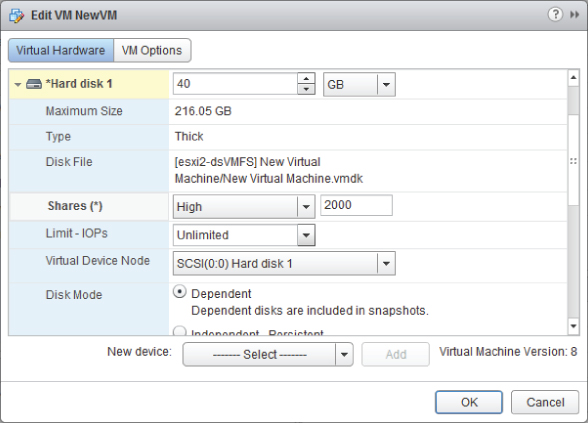
2. Select a virtual machine from the left pane, and then choose the blue Edit Settings link in the VM Hardware panel.
3. An Edit VM window will appear. In the default Virtual Hardware view, click the arrow icon to the left of the hard disk you want to configure shares for. The hard disk item will be expanded to reveal configuration options.
4. Using the drop-down menu to the right of the Shares field, change the value to High. Leave the Limit – IOPs set to unlimited.
5. Click the OK button to save the changes.
The vSphere Client can also be used to configure disk shares for a virtual machine.
Now that I have covered configuring disk shares for a virtual machine, I will cover determining the appropriate datastore locations for virtual machines based on application workloads.
Determining Appropriate Datastore Locations for Virtual Machines Based on Application Workloads
When adding virtual disks to virtual machines, two options are available in the Add Hardware Wizard for choosing the location used to store the virtual disk files:
Store With The Virtual Machine This option will store the virtual disk file in the virtual machine directory, along with the virtual machine's configuration and log files. This approach is generally easy to manage, since all of the virtual machine's files are in a single location.
Specify A Datastore Or Datastore Cluster This option will allow the virtual machine disk file to be stored on a separate datastore or datastore cluster. This approach can add complexity to the management of the VM.
Having multiple datastores and the ability to distribute virtual disks across multiple datastores can offer many advantages. Determining the appropriate datastore location will often come down to looking at the physical storage that is backing the datastore. Certain workloads will require specific disk configurations, and knowing the capabilities of the disks behind the datastore will be beneficial in determining which datastore to use.
Microsoft SQL Server is commonly configured to use both RAID5 and RAID1+0 disk configurations. With multiple datastores on differing RAID sets, this capability can easily be provided for SQL Server or other servers that have similar requirements.
If replication is being used at the storage level, any virtual machine could have its page file placed on a different virtual disk in a different datastore. This could allow very fast page file access, in addition to excluding this constantly changing disk from replication.
Applications that are read-intensive will likely perform extremely well on a datastore backed by storage that is utilizing SSD disks.
Virtual desktops can be placed on datastores backed by storage that supports deduplication.
The key thing to remember when determining the appropriate datastore location is that you will need to understand both the application's requirements and the capability of the storage system backing the datastore. In the next section, I will cover configuring and modifying vCPU and memory resources for specific application requirements.
Configuring and Modifying Virtual CPU and Memory Resources According to OS and Application Requirements
Different virtual machines will require different resources for both CPU and memory, just as physical servers have different configurations. Although it may initially seem like a good idea to give your VMs maximum memory and maximum CPU resources, it is actually a best practice to start small and grow as required. This approach both conserves resources and creates a more scalable environment.
The first step in building out a virtual machine is to look at the system requirements for the guest OS. Windows Server 2008 R2 has the following recommended system requirements:
- Processor: Single 2GHz or faster
- Memory: 2GB
At this point, you know the virtual machine needs a single vCPU and 2GB of RAM. As the second step in sizing your virtual machine, let's look at the system requirements for the application. For this example, let's look at vCenter Server, which has the following system requirements:
- Processor: Two 64-bit CPUs or one 64-bit dual-core processor
- Memory: 4GB
At this point, you know the virtual machine needs two vCPUs or a single dual-core vCPU and 4GB RAM. As the final step in sizing the virtual machine, you would add up any additional system requirements for things such as antivirus or other standard applications that will be installed on the server. Once the final number is totaled, the virtual machine may be sized accordingly using the Virtual Machine Properties Editor in the vSphere Client.
Virtual machines have the ability to grow, and even shrink if required, in a dynamic fashion. If additional applications need to be added to a server, the system requirements can be calculated and adjusted. There is no need to oversize virtual machines, when the environment is this flexible. The final step in sizing is the ongoing performance monitoring of the virtual machine. As problems are found or as the system grows beyond its original capacity, the virtual machine can continue to evolve with the workload.
Now that I have covered sizing the CPU and memory for a virtual machine, you can turn your attention to configuring and modifying network connections for virtual machines.
Configuring and Modifying Virtual NIC Adapter and Connecting Virtual Machines to Appropriate Network Resources
Configuring and modifying virtual NIC adapters is an important part of maintaining the virtual infrastructure. In many environments, there are multiple networks, and some environments will even have DMZ or external-facing networks connected to their ESXi hosts. Because of this, it is very important to understand the networking setup in a given vSphere environment. Configuring networking for a virtual machine involves selecting a network adapter type, a network connection, and the connection options. Before you configure a virtual NIC, take a look at the supported NIC types:
E1000 This is an emulated version of the Intel 82545EM Gigabit Ethernet NIC. Drivers are available in most Linux versions 2.4.19 and newer, Windows XP Professional (64-bit) and newer, and Windows Server 2003 (32-bit) and newer.
Flexible This adapter identifies itself as a Vlance adapter at boot but can function as a VMXNET adapter if the VMware Tools are installed.
Vlance This is an emulated version of the AMD 79C970 PCnet32 LANCE NIC. Drivers are available in most 32-bit guests but not for Windows Vista and newer.
VMXNET This adapter is built for virtual machines and requires the VMware Tools to provide a driver.
VMXNET 2 (Enhanced) This adapter is based on the VMXNET adapter but offers jumbo frames and hardware offload support. This adapter is available for limited guest operating systems running on ESX/ESXi 3.5 and newer and requires the VMware Tools to provide a driver.
VMXNET 3 This adapter is a paravirtualized NIC designed for performance. VMXNET 3 offers jumbo frames, hardware offloads, support for multiqueue, IPv6 offloads, and MSI/MSI-X interrupt delivery. It is important to note that VMXNET 3 is a completely different adapter than either VMXNET or VMXNET 2, and it requires the VMware Tools to provide a driver.
Now that I have covered the available virtual NIC adapters, Exercise 6.12 will cover the steps required to add and configure a virtual NIC to a virtual machine and connect the virtual machine to a network. Note that this exercise will remove the currently configured NIC for the virtual machine and replace it. Use a virtual machine that can lose network connectivity, and document the current networking information for this VM. Also ensure that this VM has the latest version of the VMware Tools installed.
Exercise 6.12: Adding, Configuring, and Connecting a Virtual NIC Adapter Using the vSphere Client
1. Connect to a vCenter Server with the vSphere Client.
2. Right-click a virtual machine in the left pane. Choose the Edit Settings option from the context menu that appears.
3. The Virtual Machine Properties window will appear. Select the listed network adapter. Take note of the Device Status options and the Network Label value.
4. With the network adapter still selected, click the Remove button at the top of the Hardware tab. Note how the network adapter is now in a strikethrough font and the Summary tab reports Removed.
5. Click the Add button at the top of the Hardware tab. The Add Hardware Wizard will launch.
6. Select Ethernet Adapter from the list of devices in the center of this screen and click the Next button.
7. Using the drop-down menu, change Adapter Type to VMXNET 3. Using the drop-down menu, change Network Label to the value from step 3 in this exercise. And using the check box for the Device Status, match the previous setting from step 3. Click the Next button.
8. Review the information on the Ready To Complete screen and click the Finish button.
9. The final configuration should look like the image shown here.
10. Click the OK button to save these changes. A Reconfigure Virtual Machine task will begin. When this task completes, the configuration is complete.
11. Because the NIC was replaced with a new one, the network configuration in the guest OS will need to be reconfigured, before the VM can be used on the network again. Follow the procedures specific to your OS for this step.
There is a field provided to specify the MAC address for a virtual NIC, but there are some fairly strict rules around this operation. Refer to the following VMware KB article for more information:
I have now covered configuring virtual NIC adapters in your virtual machines. In the following section, I will cover converting physical servers with VMware Converter.
Converting a Physical Machine Using VMware Converter
VMware Converter is an application provided by VMware that can be used to convert physical servers to virtual machines (P2V), convert virtual machines to virtual machines (V2V), reconfigure virtual machines, and import various image formats and convert them to virtual machines. In vSphere 5, VMware Converter is now a stand-alone application, and the VMware vCenter Converter plug-in for vSphere Client is no more. It should also be noted that Converter Standalone 4.3 and newer do not support cold cloning.
Cold cloning is the process of booting a physical or virtual machine to VMware Converter media and running the conversion from it. This approach allows for consistent images, because the operating system and applications would all be powered off. In VMware Converter Standalone 5, hot cloning is used. Hot cloning converts the physical server or virtual machine while it is running the guest OS and applications. To ensure consistency with hot clones, it is recommended you stop all services and applications while the conversion is in process. This will ensure that the applications and data are consistent when the conversion is complete.
The cloning process will copy data over the network. There are two primary modes used for the cloning process:
Volume Based This mode will be used if volumes are resized to a smaller size, and it will simply copy each file on the source over the network to the destination.
Disk Based This mode will be used if volumes remain the same size or are increased in size, and it will copy the disk blocks. This mode is much faster than the volume based mode.
Converter Standalone cannot detect any source volumes and file systems that are located on physical disks larger than 2TB.
It is also important to note that Ethernet controllers will change as part of the conversion process. After a P2V operation, networks will have to be reconfigured on the guest OS. The conversion and the change of the underlying hardware can also have implications for software that is licensed on MAC addresses or some other aspect of physical hardware.
VMware Converter Standalone 5 can be installed on a physical server or virtual machine either as a local installation or as a client-server installation. In Exercise 6.13, you will install VMware Converter Standalone 5 on a Windows 2008 R2 virtual machine as a local install and then use it to convert a physical server to a virtual machine.
Exercise 6.13: Installing VMware Converter Standalone and Converting a Physical Server to a Virtual Machine
1. Open a web browser and enter the following URL:
2. Log in or register and then download the VMware vCenter Converter Standalone 5 binary.
3. Verify the checksum for the downloaded file and then launch the executable to begin Setup.
4. Using the drop-down menu, choose the desired Language option, and click the OK button.
5. Click the Next button on the Welcome screen and the Patent screen. Agree to the legal terms and click the Next button.
6. Select the desired installation directory and click the Next button to continue.
7. Choose Local Installation for Setup Type and click the Next button.
8. Click the Install button. When the installation completes, make sure the Run Client Now option is checked and click the Finish button.
9. The VMware vCenter Converter Standalone application will launch. Click the Convert Machine button located in the upper-left corner of the screen, or use the File menu to choose New and Convert Machine.
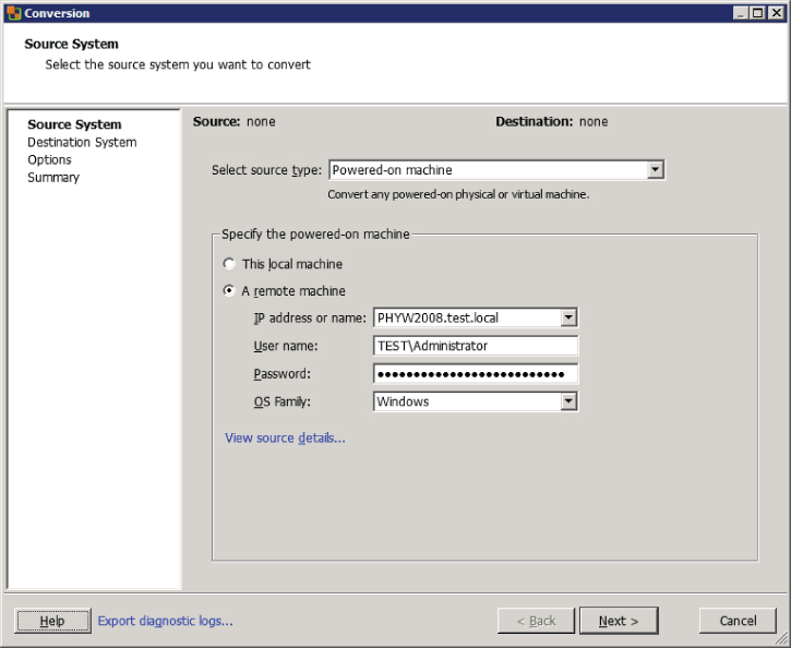
10. A Conversion Wizard will launch. Using the drop-down menu, choose the Powered-on Machine option from the Select Source Type options.
11. Specify a remote machine in the lower portion of the screen and enter the IP address or FQDN of the physical server to be converted. Also, enter a username and password that has Administrative access to the physical server. Choose the appropriate OS family, using the drop-down menu. The final configuration should look similar to the image shown here.
12. Click the blue View Source Details link. You will be prompted to install the VMware vCenter Converter Standalone agent. Choose the Automatically Uninstall The Files When Import Succeeds option and click the Yes button to continue.
13. The status of the agent deployment will be shown on the same window, and when complete, a Machine Details window will appear. Review the details here and click the Close button.
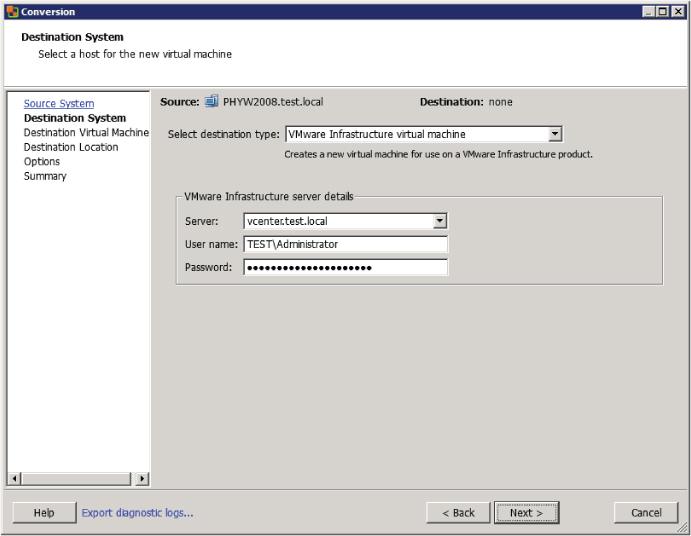
14. On the Destination System screen, select the default Destination Type of VMware Infrastructure Virtual Machine. Enter the FQDN for the vCenter Server that this virtual machine will be managed by, and enter the appropriate credentials for the vCenter Server.
15. Click the Next button to continue.
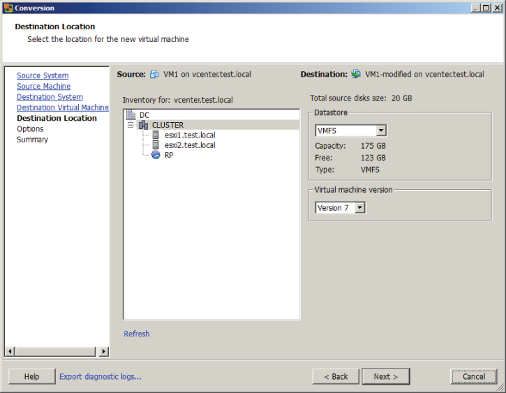
16. At the top of the Destination Virtual Machine screen, name the new virtual machine. Choose an inventory location for the new virtual machine and click the Next button to continue.
17. Now select the cluster or host that the virtual machine will be hosted on from the Inventory option in the middle of the screen. Use the drop-down menu to select a datastore and virtual machine hardware version. Click the Next button to continue.
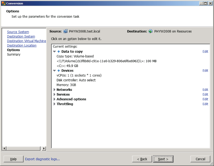
18. On the Options screen, make any changes necessary. This can include reducing the number of vCPUs, changing which disks are copied, resizing the disks that are copied, connecting and disconnecting networks, and more.
Note that any settings that are modified will have a blue diamond located in front of them. When all of the changes have been made, click the Next button.
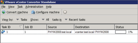
19. Review the information on the Summary screen and click the Finish button. A task will be listed in the VMware Converter Standalone window that shows the source, destination, progress, and more.
20. Selecting the task will populate the Summary and Task Progress tabs at the bottom of the screen. These tabs provide more detail on the progress.
21. When this task completes, open the vSphere Client and locate the converted server in the inventory. Power it on and watch it boot from a console session.
Converting a physical machine to a virtual machine involves much more than just running the VMware Converter. Any hardware agents, hardware management applications, and vendor-specific device drivers will need to be removed. Networking will need to be reconfigured, and some time will likely need to be spent with the system logs to ensure that everything is working properly. Only after this cleanup is complete should the applications on the converted virtual machine be started.
Now that I have covered converting a physical machine to a virtual machine using VMware vCenter Converter Standalone 5, I will cover how to import a supported VM source using VMware Converter.
Importing a Supported Virtual Machine Source Using VMware Converter
VMware Converter can also convert a variety of other sources into vSphere environments. Some of these sources include the following:
- Acronis True Image Echo
- Acronis True Image Home
- Symantec Backup Exec System Recovery
- Symantec LiveState Recovery
- Norton Ghost
- Parallels
- StorageCraft ShadowProtect Desktop
- StorageCraft ShadowProtect Server
- VMware Workstation
- VMware Fusion
- VMware Player
- VMware Server
- vCenter Server
- ESX/ESXi
- Hyper-V
Exercise 6.14 will cover the steps to import a powered-off Hyper-V virtual machine into a vSphere environment using VMware Converter. Not all test environments will have a Hyper-V virtual machine. If you have any of the other supported sources, you may substitute them as necessary in this exercise or just follow along.
Exercise 6.14: Importing a Hyper-V VM Using VMware Converter
1. Open the VMware vCenter Converter Standalone application.
2. Click the Convert Machine button located in the upper-left corner of the screen, or use the File menu to choose New and Convert Machine.
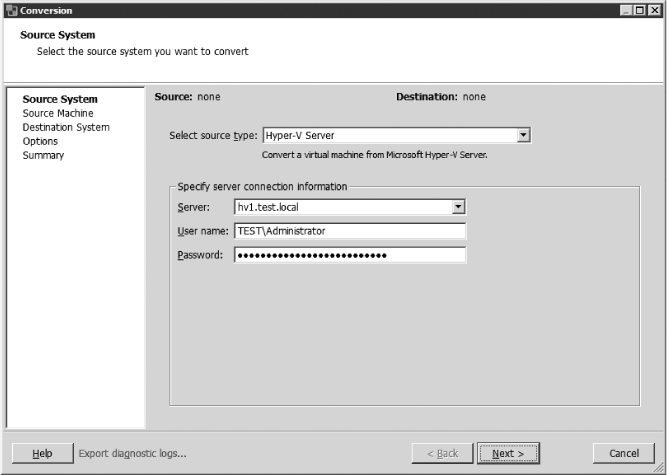
3. A Conversion Wizard will launch. Using the drop-down menu, choose the Hyper-V Server option for Source Type.
4. Enter the FQDN of the Hyper-V Server in the Server field. Enter the appropriate credentials for this Hyper-V Server and click the Next button to continue.
5. Click the Next button, and you will be prompted to install the VMware vCenter Converter Standalone agent on the remote Hyper-V host. Choose the Automatically Uninstall The Files When Import Succeeds option and click the Yes button to continue.
6. The status of the agent deployment will be shown in the same window. When the agent is deployed, the Source Machine screen will be displayed.
7. Select a powered-off Hyper-V virtual machine from the list and click the Next button.
8. Using the drop-down menu, ensure that a destination type of VMware Infrastructure Virtual Machine is selected and enter the FQDN and credentials for the vCenter Server.
9. Click the Next button. At the top of the Destination Virtual Machine screen, name the destination virtual machine. Choose an inventory location for this virtual machine and click the Next button to continue.
10. Now select the cluster or host that the virtual machine will be hosted on from the Inventory option in the middle of the screen. Use the drop-down menu to select a datastore and virtual machine hardware version. Click the Next button.
11. On the Options screen, make any changes necessary. This can include reducing the number of vCPUs, changing which disks are copied over, resizing the disks that are copied over, connecting and disconnecting networks, and more.
12. Click the Next button and review the information presented on the Summary screen. Click the Finish button to begin importing the Hyper-V source.
13. A task will be listed in the VMware Converter Standalone window that shows the source, destination, progress, and more.
14. Selecting the task will populate the Summary and Task Progress tabs at the bottom of the screen. These tabs provide more detail on the progress.
15. When this task completes, open the vSphere Client and locate the converted server in the inventory. Power it on and watch it boot from a console session.
Now that I have covered importing a virtual machine from Hyper-V Server into a vSphere environment, I will use VMware Converter to show how to modify the virtual hardware settings of a virtual machine.
Modifying Virtual Hardware Settings Using VMware Converter
So far, I have covered two ways to use VMware Converter. I showed how to perform a P2V and import a Hyper-V Server source. Another useful function that can be performed by VMware Converter is a V2V conversion within the vSphere environment. Using VMware Converter for a V2V operation is particularly useful in two situations:
- Shrinking disks
- Downgrading the virtual machine hardware version
Although virtual disks can be easily expanded, shrinking them is not as easily accomplished. Likewise, there is no mechanism in place to easily downgrade the virtual machine hardware version. A V2V operation can solve both of these problems.

Using VMware Converter for V2V Conversions
A virtual infrastructure administrator recently upgraded the virtual machine hardware version on a virtual machine in the production environment. Several days later an incident is reported by the owner of the application running on this virtual machine. The application owner reports that problems began immediately following the virtual machine hardware version upgrade.
The virtual infrastructure administrator decides to use VMware Converter to perform a V2V of the virtual machine. The V2V conversion will allow the virtual machine hardware version to be changed back to the prior version. The converted version of the application can then be loaded offline or on a test network to verify whether it functions correctly with the previous version of the virtual machine virtual hardware.
In Exercise 6.15, you will use VMware Converter to perform a V2V conversion on an existing powered-off virtual machine with virtual machine hardware version 8. You will convert this virtual machine to virtual machine hardware version 7, and you will also shrink the OS volume on this virtual machine in the process of the conversion.
Exercise 6.15: Performing a V2V Conversion to Modify Virtual Hardware Settings Using VMware Converter
1. Open the VMware vCenter Converter Standalone application.
2. Click the Convert Machine button located in the upper-left corner of the screen, or use the File menu to choose New and Convert Machine.
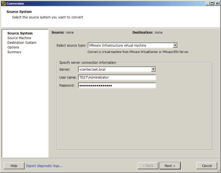
3. A Conversion Wizard will launch. Using the drop-down menu, choose the VMware Infrastructure Virtual Machine option for Source Type.
4. Enter the FQDN of the vCenter Server where the virtual machine that will be converted is located. Provide appropriate credentials for the vCenter Server and click the Next button.
5. Depending on how your environment is configured, a Converter Security Warning dialog may appear. If you trust this certificate, click the Ignore button to continue.
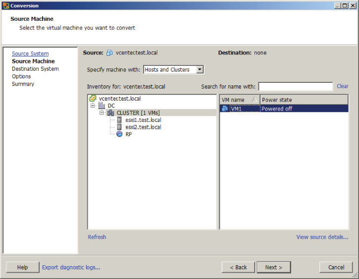
6. On the Source Machine screen, select the host, cluster, folder, or resource pool that the VM to be converted is located in. Once the VM is located in the right pane, select it by clicking it. Click the Next button.
7. On the Destination System screen, select the default destination type of VMware Infrastructure Virtual Machine. Enter the FQDN for the vCenter Server that this converted virtual machine will be managed by, and enter the appropriate credentials for the vCenter Server.
The vCenter Server selected in step 7 can be the same vCenter Server that was specified in step 4 of this exercise, but it could also be another vCenter Server. The remainder of this exercise will assume that the same vCenter Server was chosen.
8. Click the Next button, and then you may be presented with another Converter Security Warning dialog. As in step 5, you can choose Ignore if you trust your environment.
9. At the top of the Destination Virtual Machine screen, name the new virtual machine. Choose an inventory location for the new virtual machine and click the Next button to continue.
The V2V operation will create a copy of the source, so the destination VM will need to have a different name if the same vCenter Server is being used.
10. Now select the cluster or host that the virtual machine will be hosted on from the Inventory option in the middle of the screen, and use the drop-down menu to select an appropriate datastore. Change the virtual machine hardware version to Version 7 using the drop-down menu. The final configuration should look like the image shown here.
Choosing virtual machine hardware version 7 in the previous step was one objective of this exercise. In the remaining steps, you will resize the C: source volume to achieve the other objective of shrinking a virtual disk.
11. Click the Next button.
12. On the Options screen, click the blue Edit link to the right of the Data To Copy item. Using the drop-down menu for Data Copy Type, change the value to Select Volumes To Copy. The screen will refresh to show a new set of options.
13. In the row where the C: source volume is listed, locate the Destination Size column. Using the drop-down menu here, review the current size and the minimum size values.
14. Decide on a new smaller size for the C: source volume and then pick the <Type Size In GB> option from the drop-down menu. The drop-down menu will now allow you to enter this value. Enter the number only and then press the Enter key on the keyboard. The drop-down menu will now update to reflect the value you just entered. The final configuration will look like this.
15. Review the information on the Summary screen and click the Finish button to begin the V2V conversion.
16. A task will be listed in the VMware Converter Standalone window that shows the source, destination, progress, and more.
17. Selecting the task will populate the Summary and Task Progress tabs at the bottom of the screen. These tabs provide more detail on the progress.
18. When this task completes, open the vSphere Client and locate the converted virtual machine in the inventory. Right-click it and choose the Edit Settings option from the context menu that appears.
19. Verify that the virtual machine hardware version has been downgraded and that the virtual disk has been resized.
I have now covered three ways to use VMware Converter in your vSphere environment. You can now move on to the next section of this chapter, which covers creating and deploying vApps.
Create and Deploy vApps
Besides virtual machines, vSphere can also be used as a platform for running applications. This is accomplished with vApp, which is a container that consists of one or more virtual machines. These virtual machines are treated as a group in the vApp, and properties such as start order and shutdown order can be configured for the group. In this section, I will discuss vApps and how to create and use them.
Determining When a Tiered Application Should Be Deployed as a vApp
By design, a tiered application is logically separated across multiple servers. An example three-tier application in vSphere might include a web frontend running on a virtual machine, a middleware application running on another virtual machine, and a database running in yet another virtual machine. The tiered architecture has certain dependencies, and this is true in both physical and virtual environments. For example, the web server must be able to communicate with the middleware application, which must be able to communicate with the database server. These dependencies are typically covered with documentation and operational procedures.
vApp is an approach that can be used to simplify the dependencies of tiered applications, particularly when all tiers of the application are virtual machines. vApps may have specified start orders for the virtual machines they contain. This allows a tiered application to be encapsulated and treated as a unit rather than its parts. For example, a vApp can be powered up as a unit.
Using vApps
A new project has been requested from the R&D department of a customer's business. They want to create an external web-based customer portal and have requested a set of virtual machines for this project. The list of servers includes a domain controller, a database server, an application server, and a web server. They want this environment to be self-contained and have no connectivity to any of the other networks in the company.
It is decided that a vApp will be used for this project. The virtual machines will be added to the vApp, and it will function as a unit. Start order will be used to ensure the environment is both powered up and shut down in the proper sequence. Using a vApp will simplify both administrative and operational overheads, by treating the entire set of virtual machines as an application.
Now that I have discussed when a tiered application should be deployed as a vApp, I will cover creating a vApp.
Creating a vApp
Before a vApp can be used, it has to be created. vCenter Server is a requirement to use vApps. A vApp can be created in the vCenter Server datacenter object from a DRS-enabled cluster with at least one host. This is shown in Figure 6.5 with vApp1. vApps can also be created on a stand-alone ESX 3.0 or newer host. This is shown in Figure 6.5 with vApp2.
If you plan to deploy a vApp on a DRS-enabled cluster, remember that DRS requires either the Enterprise or Enterprise Plus edition of vSphere.
Exercise 6.16 will cover the steps required to create a vApp.
Exercise 6.16: Creating a vApp Using the vSphere Web Client
1. Open a web browser and connect to the FQDN of the vCenter Server and then log in to the vSphere Web Client.
2. Expand the inventory objects in the left pane and find a valid parent object for the vApp. Right-click this object and choose the Inventory ⇒ New vApp option from the context menu that appears. In the image shown here, the cluster object was used as the starting point.
3. A New vApp Wizard will launch. Give the vApp a unique name in the vApp Name field and select a datacenter or folder in which to deploy it. Click the Next button.
4. Configure the CPU and Memory Resources settings as necessary for your environment, or simply click the Next button to accept the default values.
5. Review the information on the Ready To Complete screen and click the Finish button.
6. After the vApp is created, verify that the vApp is listed in the left pane.
vApps can also be created with the vSphere Client.
You have now created a vApp. At this point, it isn't really useful, so you will next add objects (like tiered applications) to it.
Adding Objects to an Existing vApp
Objects that can be added to a vApp include virtual machines, resource pools, and other vApps. There are two options that can be used to add objects. To add new objects, using the vSphere Client, right-click the vApp and select one of the New options from the context menu. These options are shown in Figure 6.6.
The other option is to add existing objects to the vApp. This is easily accomplished in the vSphere Client or vSphere Web Client, by dragging the objects into the vApp. For example, dragging an existing virtual machine into a vApp will happen without any prompting as long as the move is allowed.
Objects can also be easily removed from a vApp by dragging them to a new location.
Using either the vSphere Client or the vSphere Web Client, take some time now and create at least one new virtual machine or add an existing virtual machine to the vApp created in Exercise 6.16. Once the vApp has been populated with objects, you will start identifying settings for the vApp.
Identifying and Editing vApp Settings
Now that you have created a vApp and added objects to it, you can identify and edit the vApp settings. Exercise 6.17 will cover identifying the various vApp settings and editing the start order options. The vSphere Client will be used for this exercise.
Exercise 6.17: Identifying vApp Settings
1. Connect to a vCenter Server with the vSphere Client.
2. Right-click a vApp in the left pane. Choose the Edit Settings option from the context menu that appears.
3. An Edit vApp Settings window will appear, as shown here.
The Options tab's Resources setting is displayed by default. The Resources setting is used to specify CPU and memory resources for the vApp. Configuring these options is similar to configuring the options for a resource pool, which will be covered in Chapter 8.
4. On the Options tab, click the Properties option in the left pane. This will display any properties that have been defined for the vApp.
5. Click the IP Allocation Policy option in the left pane. This will display the IP allocation policy that the vApp uses. This option will be discussed later in this chapter.
6. Click the Advanced option in the left pane. This will display any information that has been entered about the vApp. There are also two options at the lower part of this screen that can be used to assign advanced properties or the IP address allocation scheme that is used in the IP Allocation Policy option.
7. Click the Start Order tab. This tab displays the order in which the virtual machines in this vApp will be both started and shut down.
Notice that in this image there are two groups. The first group, Group 1, contains a DNS server. No virtual machines in Group 2 will be powered on until the DNS server is first powered up. Then in Group 2, the database server will first be powered up. It will be followed by the application server and finally the web server.
8. Select a virtual machine in the left pane. In the Startup Action section on the right, select the VMware Tools Are Ready check box.
This option will allow the subsequent virtual machines to start up sooner than the 120-second delay if the VMware Tools start sooner. The VMware Tools starting is generally a good sign that the VM is up and running.
9. In the Shutdown Action section on the right, use the drop-down menu to change the default Operation to Guest Shutdown. When this change has been made, the Shutdown Sequence timer becomes enabled.
These changes can be made or customized for each virtual machine in the list. This allows finer control over how the vApp starts up.
10. Now click the vServices tab and note that there are no dependencies defined.
vServices are used to provide access to a service across a network, and a vService Dependency can be used to make a VM or vApp dependent on a vService before starting.
11. Click the OK button on the Edit vApp Settings window to save the changes made to the Start Order in steps 8–9.
12. An Update vApp Configuration task will begin.
I have now covered identifying the various vApp settings and editing the Start Order Startup and Shutdown actions. In the next section, I will cover configuring IP pools for a vApp.
Configuring IP Pools
An IP pool is a network configuration stored in vCenter. The IP pool is associated with one or more virtual machine port groups and can be used to provide IP addresses to virtual machines in a vApp.
An IP pool does not provide the same functionality as a DHCP server. Leveraging IP pools for addressing requires some type of support inside the guest OS of the VMs that make up the vApp.
Exercise 6.18 will cover the steps required to configure an IP pool and set up a vApp to use it.
Exercise 6.18: Configuring an IP Pool and vApp
1. Connect to a vCenter Server with the vSphere Client.
2. Select the Hosts and Clusters view and select the datacenter that contains the vApp. In the right pane, click the IP Pools tab.
3. Click the blue Add link at the top of the IP Pools tab. A New IP Pool Properties window will appear.
4. Enter a value for the IP Pool Name, at the top of the IP Pool Properties window.
5. Using either the IPv4 or IPv6 tab, enter the appropriate subnet and gateway information. Select the Enable IP Pool box and then enter the ranges. An example of the setup for IPv4 is shown here.
Note that the range is a starting IP address, a number sign (#), and a number that represents the value of the range. In the previous image, the range starts at 172.16.0.2 and includes the next 253 addresses. The gateway and broadcast address are always excluded from the range.
6. You can also click the blue View link at the end of the Ranges text box to view the addresses that would be available in the range.
7. Click the DHCP tab. Select the IPv4 DHCP Present box. This option will be discussed in more detail later in this exercise.
8. Click the DNS tab. Populate these fields as appropriate for your environment.
9. Click the Proxy tab. Enter the server name and port number for an HTTP proxy server, if your environment has one.
10. Click the Associations tab. Select at least one of the virtual machine port groups listed here. Click the OK button to save the IP Pool.
11. The IP Pool will now be listed in the IP Pools list in the left pane, and its details appear in the right pane.
At this point the IP pool has been created and is ready to be used. The remainder of this exercise will show how to associate the vApp with this IP pool.
12. Locate the vApp in the left pane and expand its contents. Verify that each VM is connected to a virtual machine port group that you associated the IP pool with in step 10.
13. Select the vApp and right-click it. Choose the Edit Settings option from the context menu that appears. An Edit vApp Settings window will appear.
14. On the Options tab, select Advanced from the left pane. Click the IP Allocation button in the bottom-right corner. An Advanced IP Allocation window will appear.
15. Select the OVF Environment box. Use the drop-down menu in the IP Protocol section to select one of the three options of IPv4, IPv6, or Both.
In the Advanced IP Allocation window, the DHCP option could have also been selected. Selecting this option would allow the vApp to use the DHCP Server entered on the DHCP tab of the IP Pool configuration from step 7 of this exercise. This exercise covers IP pools, so you will use only the OVF Environment option.
16. Click the OK button on the Advanced IP Allocation window to save these changes.
17. In the Edit vApp Settings window, select the IP Allocation Policy option in the left pane. Select the Transient IP Allocation policy.
Note that the DHCP option is grayed out. If the DHCP option had been selected in step 15 of this exercise, then the DHCP option would be available as an option in this screen. Again, this configuration would be used to utilize DHCP and not an IP pool.
18. Click the OK button to save the changes. An Update vApp task will begin. When this task completes, configuration of the IP pool and the vApp is complete.
Before I leave IP pools behind, I will review the IP allocation policies for a vApp. The three available policies are as follows:
Fixed This policy is used when the virtual machines in the vApp are configured with static IP addresses.
Transient This policy is used when the virtual machines in the vApp are configured to use IP pools.
DHCP This policy is used when the virtual machines in the vApp are configured to use a DHCP server to acquire IP addresses.
Now that I have covered IP pools, I will discuss suspending and resuming a vApp.
Suspending and Resuming a vApp
Like virtual machines, vApps can also be suspended and resumed. To suspend a vApp, using the vSphere Client, right-click the vApp and choose the Suspend option from the context menu that appears. You will then be prompted to confirm suspension of the vApp. Virtual machines are suspended based on the reverse start order, and this order can be confirmed by viewing the tasks listed in the Recent Tasks pane in the vSphere Client. Figure 6.7 shows the suspend option in the vSphere Client.
To resume a vApp, using the vSphere Client, right-click the vApp and choose the Power On option from the context menu that appears. Virtual machines will be resumed as specified in the start order, and this order can be confirmed by viewing the tasks listed in the Recent Tasks pane in the vSphere Client. Figure 6.8 shows the Power On option in the vSphere Client.
I have now covered suspending and resuming a vApp; next I will cover cloning and exporting a vApp.
Cloning and Exporting a vApp
vApps can be cloned and exported, just as virtual machines can. Exercise 6.19 will cover the steps required to clone a vApp using the vSphere Client.
Exercise 6.19 Cloning a vApp Using the vSphere Client
1. Connect to a vCenter Server with the vSphere Client.
2. Right-click the vApp in the left pane. Choose the Clone option from the context menu that appears.
3. The Clone vApp Wizard will launch. Select a destination host, cluster, or resource pool for the cloned vApp and click the Next button.
4. Provide the cloned vApp with a unique name and select an inventory location for it. Click the Next button.
5. Select a datastore for the cloned vApp and click the Next button.
6. Select the appropriate disk format and click the Next button.
7. Review the information presented on the Ready To Complete screen and click the Finish button to begin the vApp clone.
8. A Clone vApp task will begin. When this task completes, verify that the cloned vApp is listed in the inventory.
You have now cloned a vApp. Cloning vApps is useful in instances where a copy of a vApp is needed, perhaps for a new test or development environment.
Exporting a vApp is often useful in the same instances that cloning a vApp is useful, but exported vApps can also be imported on different systems in different locations. Exercise 6.20 will cover the steps required to export a vApp.
Exercise 6.20: Exporting a vApp Using the vSphere Client
1. Connect to a vCenter Server with the vSphere Client.
2. Locate the vApp in the left pane and select it. Use the File menu in the vSphere Client to choose the Export option and then choose the Export OVF Template option.
3. The Export OVF Template window will appear.
4. Provide a descriptive name for the OVF template. This will be the name of the file, used in the directory in the next field.
5. Choose a directory with adequate free space to hold the OVF template. The directory chosen here is where the OVF template will be saved to on the same system that the vSphere Client is being run from.
6. Using the drop-down menu, choose the Single File (OVA) format option.
Two options are available here:
Folder Of Files (OVF)
This option is used to package the OVF template as a set of files (.ovf, .vmdk, and .mf).
Single File (OVA)
This option is used to package the OVF template into a single .ova file.
7. Provide a description for the OVF template.
If any virtual machines in the vApp are connected to an ISO file or floppy image, there will be an option allowing you to include these image files as part of the OVF template.
8. If applicable, choose whether to include image files.
9. The final configuration should look similar to the image shown here.
10. Click the OK button. An Export OVF Template task will begin, and a dialog box will appear that provides the progress of the export operation.
11. When this task completes, verify that the vApp was exported to the location you selected on the local file system.
Now that you have cloned and exported a vApp, this chapter is complete. In the next chapter, you will continue to work with virtual machines.
Summary
This chapter covered creating and deploying virtual machines. Knowing how to create and deploy virtual machines is absolutely essential for any virtual infrastructure administrator. In this chapter, I covered identifying the capabilities of the different virtual machine hardware versions and configuring and deploying a virtual machine. How to place VMs in selected ESXi hosts, resource pools, and clusters was covered. I also discussed the various methods that can be used to access and use a virtual machine console. Installing, upgrading, and updating the VMware Tools and the VMware Tools device drivers were covered. I covered configuring virtual machine time synchronization and identifying virtual machine storage resources. I configured disk controllers for virtual disks, appropriate virtual disk types, and disk shares and discussed creating and converting thin and thick provisioned virtual disks. I covered determining appropriate datastore locations for virtual machines based on application workloads. I also covered configuring and modifying vCPU and memory resources according to OS and application requirements. Configuring and modifying virtual NIC adapters and connecting VMs to appropriate network resources were also covered. The first part of this chapter concluded with using VMware Converter to perform a P2V conversion, import a Hyper-V virtual machine, and perform a V2V to modify virtual hardware settings.
The final part of this chapter focused on creating and deploying vApps. Determining when a tiered application should be deployed as a vApp was discussed. I covered creating a vApp and adding objects to an existing vApp. I also covered identifying and editing the settings of a vApp. I configured an IP pool for the vApp and covered suspending and resuming a vApp. I concluded this chapter by covering how to clone and export a vApp.
Exam Essentials
Know how to create and deploy virtual machines. Be able to identify the capabilities of virtual machine hardware versions. Know how to configure and deploy a guest OS into a new virtual machine and how to place the VM in ESXi hosts, clusters, and resource pools. Be able to identify the methods used to access virtual machine consoles. Know how to install, upgrade, and update the VMware Tools and be able to identify the different VMware Tools device drivers. Be able to configure virtual machine time synchronization and identify virtual machine storage resources. Know how to configure and modify disk controllers, virtual disk types, and disk shares. Understand how to create and convert thin provisioned virtual disks. Be able to determine appropriate datastore locations for virtual machines based on application workloads. Know how to configure and modify vCPU and memory resources according to OS and application requirements. Understand how to configure and modify virtual NIC adapters and connect virtual machines to the appropriate network resources. Understand the P2V process using VMware Converter. Know how to import a supported VM source using VMware Converter, and know how to perform a V2V with VMware Converter to modify virtual hardware settings.
Know how to create and deploy vApps. Be able to determine when a tiered application should be deployed as a vApp. Know how to create a vApp and add objects to it. Be able to identify and edit vApp settings. Understand how to configure and use IP pools. Know how to suspend and resume a vApp, in addition to how to clone and export a vApp.
Review Questions
1. You updated the virtual machine hardware version for a virtual machine from version 7 to version 8. Several days later an application on this virtual machine is being reported as no longer working. You need to return the virtual machine back to the previous virtual hardware version. How do you do this?
A. Use the vSphere Client to change the version.
B. Use the vSphere Web Client to change the version.
C. Use VMware Converter to change the version.
D. None of these is correct.
2. Which of the following methods can be used to configure and deploy a new virtual machine? (Choose all that apply.)
A. vMA
B. vSphere Client
C. vSphere Web Client
D. vApp
3. You have a virtual machine with a single 20GB thin disk with 40 percent free space. The virtual machine needs to have a SAN-aware application installed that will consume 100MB of additional disk space. What type of disk should you add to this virtual machine?
A. Physical Compatibility Mode RDM.
B. Virtual Compatibility Mode RDM.
C. No disk needs to be added.
D. None of these is correct.
4. Which of the following are VMware device drivers loaded by the VMware Tools? (Choose all that apply.)
A. Mouse
B. VMCI
C. VMXNet
D. Memory Control
5. Which editions of vSphere include the VMware vCenter Converter plug-in? (Choose all that apply.)
A. Essentials
B. Enterprise
C. Enterprise Plus
D. None of these
6. Which of the following can be used to clone a vApp?
A. VMware Converter
B. vSphere Client
C. vSphere Web Client
D. vMA
7. Which type of SCSI bus sharing allows virtual disks to be shared by virtual machines located on the same ESXi host?
A. None
B. Local
C. Physical
D. Virtual
8. Which of the following DHCP servers can be specified in the IP pools of a vApp?
A. Either IPv4 or IPv6 DHCP servers
B. Both IPv4 and IPv6 DHCP servers
C. Only IPv4 DHCP servers
D. Only IPv6 DHCP servers
9. Which of the following NICs are paravirtualized?
A. vlance
B. VMXNET
C. VMXNET 2
D. VMXNET 3
10. Which of the following objects may be added to an existing vApp? (Choose all that apply.)
A. Virtual machines
B. Resource pools
C. vApps
D. Folders
11. Which of the following statements are correct about the VMware Tools? (Choose two.)
A. The VMware Tools are required for virtual machines.
B. The VMware Tools are required only for advanced functionality in virtual machines.
C. An automatic VMware Tools upgrade can reboot the guest OS without prompting.
D. An interactive VMware Tools upgrade can reboot the guest OS without prompting.
12. Which of the following statements are true about the start order for the virtual machines in a vApp? (Choose two.)
A. Each group is started at the same time, and virtual machines in the groups are started in the order listed.
B. Each virtual machine in the same group is started in the order listed, before the next group begins.
C. Shutdown is performed in reverse order of the start order.
D. Shutdown is performed as a simultaneous operation against all virtual machines in the vApp.
13. Which disk mode results in a disk that loses all changes at virtual machine power-off or reset?
A. Independent Persistent
B. Dependent Persistent
C. Independent Nonpersistent
D. Dependent Nonpersistent
14. You want to use VMware Converter to import a Hyper-V hosted virtual machine into your vSphere 5 environment. Which of the following is the correct way to perform this operation?
A. Run VMware Converter with the Hyper-V virtual machine running.
B. Power off the Hyper-V virtual machine and run VMware Converter.
C. Power off the Hyper-V virtual machine and copy its files to the system where VMware Converter is installed. Then import the Hyper-V VM locally.
D. Use the vSphere Client with the VMware vCenter Converter plug-in to import the Hyper-V virtual machine.
15. You plan to deploy a vApp on a DRS-enabled cluster. Which editions of vSphere will you be able to accomplish this with? (Choose all that apply.)
A. Essentials Plus
B. Standard
C. Enterprise
D. Enterprise Plus
16. Which of the following are capabilities of virtual machine hardware version 8? (Choose two.)
A. 32 vCPU
B. 64 vCPU
C. 512GB RAM
D. 1TB RAM
17. What are the three options available for choosing the location used to store the virtual disk files? (Choose three.)
A. With the virtual machine
B. In a datastore different from the virtual machine
C. In a datastore cluster
D. In a resource pool
18. Which of the following methods can be used to convert a thin disk to a thick disk? (Choose all that apply.)
A. The Datastore Browser Inflate option
B. Storage vMotion
C. VMware Converter
D. vmkfstools
19. Which of the following options can be used to disable periodic time synchronization? (Choose two.)
A. VmwareToolboxCmd.exe
B. vmware-toolbox-cmd
C. vSphere Client
D. vSphere Web Client
20. Which of the following methods can be used to obtain virtual machine console access? (Choose all that apply.)
A. vSphere Client
B. vSphere Web Client
C. ESXi Shell
D. VMware Converter