
Chapter 8
Establish Service Levels with Cluster, Fault Tolerance, and Resource Pools
VCP5 Exam Objectives Covered in This Chapter:
- Creating and Configuring VMware Clusters
- Determine appropriate failover methodology and required resources for an HA implementation
- Describe DRS virtual machine entitlement
- Create/Delete a DRS/HA Cluster
- Add/Remove ESXi Hosts from a DRS/HA Cluster
- Add/Remove virtual machines from a DRS/HA Cluster
- Enable/Disable Host Monitoring
- Configure admission control for HA and virtual machines
- Enable/Configure/Disable virtual machine and application monitoring
- Configure automation levels for DRS and virtual machines
- Configure migration thresholds for DRS and virtual machines
- Create VM-Host and VM-VM affinity rules
- Configure Enhanced vMotion Compatibility
- Monitor a DRS/HA Cluster
- Configure Storage DRS
- Planning and Implementing VMware Fault Tolerance
- Determine use case for enabling VMware Fault Tolerance on a virtual machine
- Identify VMware Fault Tolerance requirements
- Configure VMware Fault Tolerance networking
- Enable/Disable VMware Fault Tolerance on a virtual machine
- Test an FT configuration
- Creating and Administering Resource Pools
- Describe the Resource Pool hierarchy
- Define the Expandable Reservation parameter
- Create/Remove a Resource Pool
- Configure Resource Pool attributes
- Add/Remove virtual machines from a Resource Pool
- Determine Resource Pool requirements for a given vSphere implementation
- Evaluate appropriate shares, reservations and limits for a Resource Pool based on virtual machine workloads
- Clone a vApp
This chapter will cover the objectives of sections, 5.1, and 5.2 of the VCP5 exam blueprint. This chapter will focus on clusters, VMware Fault Tolerance (FT), and resource pools.
This chapter will first cover discussing HA implementation resources and failover methodologies. I will cover describing virtual machine entitlement, along with some basic information about DRS and HA. I will cover the steps required to create and delete a DRS/HA cluster, as well as how to add and remove ESXi hosts from a DRS/HA cluster. I will also cover the steps to monitor a DRS/HA cluster. I will show how to enable and disable host monitoring in a cluster and cover how to configure admission control for HA and VMs. Virtual machine and application monitoring will be covered, along with automation levels for DRS and virtual machines. Configuring the migration thresholds for DRS and virtual machines will be covered. I will cover how to create VM-Host and VM-VM affinity rules. EVC compatibility and monitoring clusters will also be covered. This section will conclude with configuring Storage DRS.
The second section of this chapter will cover the VMware Fault Tolerance feature. I will cover determining the use cases for VMware FT and identifying the requirements to implement FT in a vSphere environment. I will also cover how to create networking for the Fault Tolerance logging traffic. I will cover the steps to enable and disable FT and to test it.
The final section of this chapter will focus on resource pools. The resource pool hierarchy will be described, and the Expandable Reservation parameter will be discussed. I will show how to create and remove resource pools, configure their attributes, and add and remove virtual machines to a resource pool. I will also cover how to determine the resource pool requirements for a given vSphere implementation. I will evaluate appropriate shares, reservations, and limits for a resource pool, based on VM workloads. This chapter will conclude with reviewing the procedure for cloning a vApp.
Creating and Configuring VMware Clusters
In vSphere, a cluster is a collection of ESXi hosts and the virtual machines associated with them that have shared resources and are managed by vCenter Server. Clusters are used to enable some of the more powerful features in vSphere, such as DRS, HA, FT, and vMotion. The first topic I will cover in this chapter is determining the appropriate failover methodology and required resources for an HA implementation.
Determining the Appropriate Failover Methodology and Required Resources for an HA Implementation
As you will see later in this chapter, creating clusters and configuring clusters in vCenter Server are both relatively simple tasks. Like many aspects of vSphere, creating a cluster involves proper up-front planning. Part of this planning is determining how you want the cluster to function. Will the cluster have both DRS and HA enabled, or perhaps just one and not the other? The answers to these questions will impact the way the cluster is designed. Remember that DRS provides load balancing and HA provides high availability. While these two features complement each other well, they serve different functions and don't always have to be used in unison.
For clusters that will use HA, determining the resources that will be required is in part determined by how failures in the cluster will be handled. For example, are all virtual machines required to have a certain amount of uptime? If you have a two-node cluster, with each ESXi host running at 80 percent capacity of memory and processing, then a single host failure will not likely allow you to achieve the virtual machine availability requirements. The failover behavior is handled by admission control policies in the HA cluster and will be discussed later in this chapter.
Knowing your environment's specific availability requirements will determine the appropriate failover methodology and help you determine the resources required for an HA implementation. In the next section, I will describe DRS virtual machine entitlement.
Describing DRS Virtual Machine Entitlement
While each ESXi host has its own local scheduler, enabling DRS on a cluster will create a second layer of scheduling architecture. Figure 8.1 shows this architecture.
Figure 8.1 Global and local schedulers

Both of these schedulers compute resource entitlement for virtual machines. This resource entitlement is based on both a static and dynamic entitlement. The static entitlement consists of a virtual machine's shares, reservations, and limits. The dynamic entitlement for the virtual machine consists of metrics such as estimated active memory and CPU demand.
If the DRS cluster is not overcommitted, then the virtual machine entitlement will be the same as the resource allocation for the virtual machine. In periods of contention, DRS will use the virtual machine entitlement to determine how to best distribute resources.
Now that I have described the virtual machine entitlement, I will cover how to create and delete a cluster.
Creating and Deleting a DRS/HA Cluster
Once the planning and design work is done, creating a cluster is simple. Exercise 8.1 will cover the steps to use the vSphere Client to create a new cluster with HA and DRS enabled.


The newly created cluster likely has a warning, because of the lack of shared storage. Clusters can exist without shared storage, but nearly all of the functionality they provide will require shared storage. Before proceeding, please add shared storage to any ESXi hosts that will be added to the cluster you just created. If you need assistance, check Chapter 5 where I showed how to configure shared storage. The remainder of the exercises in this chapter will assume that the same shared storage is available for each ESXi host in the cluster created in Exercise 8.1.
Another configuration that should exist in each ESXi host in the cluster is VMkernel networking for vMotion traffic. Having vMotion configured enables DRS to migrate virtual machines to different hosts. Exercises 4.4 and 4.15 in Chapter 4 covered configuring vMotion networking, if you need assistance with this step. The remainder of the exercises in this chapter will also assume that vMotion has been configured for each ESXi host in the cluster created in Exercise 8.1.
Occasionally, you might need to delete a cluster. The steps to delete a cluster are simple and consist of right-clicking a cluster in the left pane of the vSphere Client and choosing the Remove option from the context menu that appears. A Remove Cluster confirmation dialog will appear, and clicking the Yes button will delete the cluster.

The steps to create and delete a DRS- and HA-enabled cluster have been covered. However, a cluster with no ESXi hosts is not very functional, so in the next section I will cover how to add ESXi hosts to this cluster.
Adding and Removing ESXi Hosts from a DRS/HA Cluster
Like vCenter Server, a cluster isn't nearly as interesting until ESXi hosts have been added to it. In the previous exercise, I created a new cluster with DRS and HA enabled. In Exercise 8.2, two ESXi hosts will be added to this cluster. This exercise will assume that there is one host already present in the same datacenter as the cluster and that the second host will be added to the cluster as a new host.

Choosing the default option here will put all of the ESXi host's virtual machines in the cluster's root resource pool and will delete any resource pools currently defined on the ESXi host.
You have now added an existing ESXi host from your datacenter into a new cluster. The remainder of the exercise will cover the steps to add a host that was not already being managed by a vCenter Server.


Moving forward, you will need to have at least two ESXi hosts in the cluster, so move the ESXi host back into the cluster now. Once it is back in the cluster, exit maintenance mode on the ESXi host.
You have now added two ESXi hosts to the cluster. Any virtual machines that were already present on either of these two ESXi hosts are now automatically part of the cluster. In the next section, I will cover adding and removing new virtual machines to the cluster.
Adding and Removing Virtual Machines to/from a DRS/HA Cluster
The process of adding a virtual machine to a cluster is very similar to the process of adding a virtual machine to a host or vApp. In chapters 6 and 7 I covered adding virtual machines to ESXi hosts and vApps, deploying OVF templates, and moving machines with VMware Converter. Each of these deployment options allows you to choose a cluster, so adding a virtual machine to a cluster should certainly be familiar ground by now.
To create a new VM that will be a member of a cluster, simply right-click the cluster and choose the New Virtual Machine option from the context menu that appears. One difference when using the Create New Virtual Machine Wizard to add a virtual machine to a cluster is that the option to pick a host or cluster is no longer presented in the configuration options. This is shown in Figure 8.2.
Figure 8.2 No host/cluster option for VM

Virtual machines running on ESXi hosts in the same datacenter but not in the cluster can also be added to the cluster. This could be used for a VM that was in a testing or pilot program but is now ready to be moved into production and benefit from DRS and HA. In Exercise 8.3, the steps to move a powered-on VM from another host to a cluster will be covered. This exercise will require an additional ESXi host that is not part of the cluster and, as mentioned earlier in this chapter, assumes that a vMotion network and shared storage exist for all of the ESXi hosts.

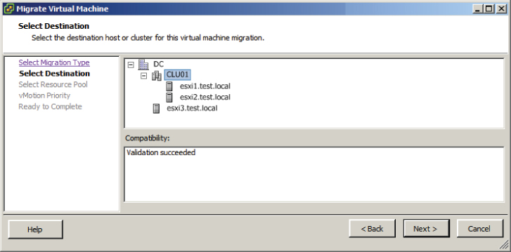
Removing a virtual machine is accomplished in much the same way that a virtual machine is added to a cluster. vMotion can be used to migrate a powered-on VM from a cluster to another host with access to both the vMotion network and the same shared storage. If the vMotion network and shared storage requirements are not met, then the VM can be cold migrated from the cluster to an ESXi host.
You have now created a cluster, added ESXi host(s) to it, and added virtual machines to it. Next I will begin to explore some of the options available in the cluster settings.
Enabling and Disabling Host Monitoring
In Exercise 8.1, you created a DRS/HA cluster, and there were two HA settings that were modified from the default settings. These changes were to disable host monitoring and to disable admission control. Changing these settings initially allowed the cluster to be more flexible for a lab-type environment. Now that the cluster is built and hosts and VMs are running in it, I will configure the HA settings. First I will cover enabling host monitoring.
To begin, right-click the cluster object and choose the Edit Settings option from the context menu that appears. Select vSphere HA in the left pane. Figure 8.3 shows the vSphere HA settings.
The first field is used to enable and disable host monitoring. Enable host monitoring here by selecting the Enable Host Monitoring option. Click OK to save the changes.
Enabling host monitoring will allow ESXi hosts in the cluster to exchange network heartbeats via the HA agents over their management networks. To understand how this works, it is first necessary to discuss how HA works in vSphere 5. HA is completely redesigned in vSphere 5 and now utilizes a master-slave host design. In this design, a single member of the cluster is the master host, while all other hosts are slaves. For network heartbeating, the master host monitors the status of the slave hosts.
If the master host stops receiving network heartbeats from a slave host, it must determine whether the host is failed, isolated, or partitioned. To determine which type of event has occurred, the master host will try to exchange heartbeats with a datastore. This is known as datastore heartbeating and allows the master host to better determine the true state of the slave host(s).
Figure 8.3 vSphere HA options

If the master host can no longer receive heartbeats via the HA agent on the slave host, the slave host is not responding to pings, and the datastore heartbeats are not occurring from the slave host, then the slave host is considered failed. HA will restart the virtual machines that were running on the slave host.
If a slave host is still running but network heartbeats are not being received via the HA agents, the master host will attempt to ping the cluster isolation address. If this ping operation fails, the slave host is considered isolated. The master host will now utilize the host isolation response to determine what action to take with the virtual machines.
If a slave host is no longer receiving network heartbeats from the master host but is able to communicate with other slave hosts, then the slave host is considered partitioned. An election process will take place among the slave hosts in the partition to determine a new master host. This is considered a degraded protection state but will allow the hosts in the cluster to resume the ability to detect failed hosts or isolated hosts so that the correct HA action can be taken.

Host monitoring can be disabled for network or ESXi host maintenance in lab settings or other configurations where you would not want HA to function as normal, such as when first building out the cluster. Now that I have covered host monitoring, I will cover admission control and configuring the admission control policy.
Configuring Admission Control for HA and Virtual Machines
Admission control is used to guarantee that capacity exists in the cluster to handle host failure situations. The current available resources of the cluster are used by admission control to calculate the required capacity, so this value will be dynamic. Placing a host in maintenance mode or experiencing a host failure will change the capacity calculations for the cluster. Admission control attempts to ensure that resources will always be available on the remaining hosts in the cluster to power on the virtual machines that were running on a failed or unavailable host. The recommended configuration for admission control is to enable it. This will allow the cluster to reserve the required capacity and keep you out of host resource saturation situations.
Admission control is further configured by selecting the admission control policy. These policies are used to further define how admission control will ensure capacity for the cluster. The three policies are as follows:
- Host failures the cluster tolerates
- Percentage of cluster resources reserved as failover spare capacity
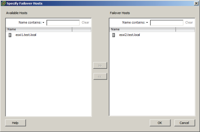
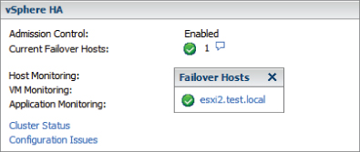
- Specify failover hosts
Each of these three options will now be discussed in more detail, but also keep in mind that HA is a complex subject and that multiple chapters could easily be devoted to it.
Now that I have briefly discussed admission control and the admission control policies, I will show how to configure both in Exercise 8.4.
The final configuration should look like this.
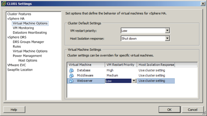
One other item that needs to be addressed is the virtual machine options for vSphere HA. These options are also listed in the cluster settings and are contained in the vSphere HA options. Figure 8.4 shows the Virtual Machine Options screen.
Figure 8.4 Virtual Machine Options screen for HA
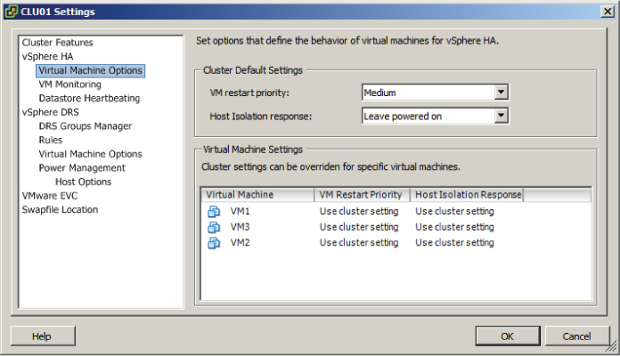
The Virtual Machine Options section of the cluster settings is used to specify the restart priority and host isolation response for both the cluster and the individual virtual machines. The virtual machine restart priority is used to specify the start order for virtual machines, if an HA event occurs. VMs with the highest restart priority are restarted first. This setting can be used to ensure that important virtual machines get powered on first. It is also useful in cases where cluster resources become exhausted in an HA event, to ensure that the more important VMs are powered on.
If you recall the vApp start order options I discussed in Chapter 6, VM restart priority can be used in a somewhat similar way. In an application with a three-tiered architecture, the database server could have a High restart priority, the application server could have a Medium priority, and the web server frontend could have a Low priority. While there will be no guarantees, like with a vApp, it is still a sound approach. There are four settings for virtual machine priority:
- Disabled
- Low
- Medium
- High
The Disabled option can be used to disable HA for virtual machines. This could be useful for clusters that include nonessential virtual machines.
Host isolation response is used configure the behavior of the ESXi host when it has lost its management network connection but has not failed. When a host is no longer able to communicate with the HA agents running on other ESXi hosts in the cluster and is also unable to ping its isolation address, it is considered isolated. Once isolated, the host will execute the isolation response. The isolation responses are as follows:
- Leave powered on
- Power off
- Shut down
These options are self-explanatory, but do know that the shutdown isolation response requires that the guest operating systems have the VMware Tools installed. Now that I have discussed vSphere HA options for virtual machines, I will show how to configure them in Exercise 8.5.
These options will configure HA to shut down the database cleanly and then restart this virtual machine with a high priority. Note that individual virtual machine priority settings will override those of the cluster.
These options will configure HA to shut down the middleware virtual machine and then restart it with a medium priority. Note again that individual virtual machine priority settings will override those of the cluster.
These options will configure HA to shut down the web server frontend for the application and then restart it with a low priority.
I have now covered admission control, covered admission control policies, and configured admission control for a cluster with DRS and HA enabled. I also discussed and configured the virtual machine options within HA. Enabling, configuring, and disabling virtual machine and application monitoring will be covered next.
Enabling, Configuring, and Disabling Virtual Machine and Application Monitoring
VM monitoring is used to provide high availability for individual virtual machines. Where vSphere HA can restart virtual machines when a host fails or becomes isolated, VM monitoring can restart individual virtual machines when they have failed or become unresponsive. Application monitoring works in much the same way, except that a specific application is monitored rather than the virtual machine.
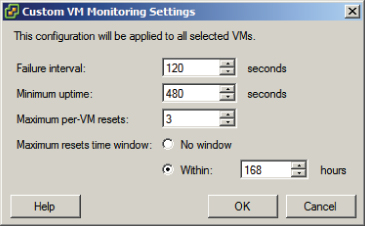
VM monitoring works by monitoring VMware Tools heartbeats and I/O activity from the VMware Tools process running in the guest OS. If VMware Tools heartbeats stop for the duration of the failure interval, the last 120 seconds of disk I/O activity will be checked. If there is no disk I/O in this period, the virtual machine will be reset.
Virtual machine monitoring sensitivity can also be configured for the cluster and for individual VMs. This allows you to fine-tune the monitoring sensitivity both to obtain rapid resolution and to avoid false positives. Table 8.1 shows the VM monitoring sensitivity values for the cluster setting.
Table 8.1 VM monitoring sensitivity settings
| Setting | Failure interval | Reset period |
| High | 30 seconds | 1 hour |
| Medium | 60 seconds | 24 hours |
| Low | 120 seconds | 7 days |
Virtual machines can be configured individually so that an individual VM can have settings that override those of the cluster. These options are configured in the VM Monitoring section of the cluster settings and will be discussed in more detail in Exercise 8.6.
Application monitoring performs similarly to VM monitoring. It differs in that it uses heartbeats from a specific application and thus requires the application to be customized to utilize VMware application monitoring.
In Exercise 8.6, I will show how to enable and configure VM and application monitoring.
Note that this will enable the VM to be restarted if no heartbeat or I/O is detected within a two-minute interval. The virtual machine can be restarted up to three times within the reset period of seven days. If the VM fails a fourth time within the reset period, vSphere HA will take no further action. The remainder of this exercise will again make use of the three-tiered application example. Replace these virtual machines with those in your own lab as necessary.
The database server has now been excluded from VM and application monitoring.

I have now covered enabling and configuring virtual machine and application monitoring for vSphere HA. Next I will move on to DRS and configuring automation levels for DRS and virtual machines.
Configuring Automation Levels for DRS and Virtual Machines
Since DRS is responsible for both the initial placement of virtual machines and migrations using vMotion, automation levels can be configured to help control how involved the distributed resource scheduler will actually be. Table 8.2 shows the available automation levels and a description of each.
Table 8.2 VM monitoring sensitivity settings
| Automation level | Description |
| Manual | No action will be taken, and vCenter Server will inform of suggested virtual machine migrations. |
| Partially automated | vCenter Server will inform of suggested virtual machine migrations and place the virtual machines on ESXi hosts at VM startup. |
| Fully automated | vCenter Server will use vMotion to optimize resource usage in the cluster and place the virtual machines on ESXi hosts at VM startup. |
The automation level can be set for the entire DRS cluster, but virtual machines may have their individual automation levels set to override the cluster settings. In Exercise 8.7, I will set the automation level for a cluster and set a virtual machine's individual automation level to differ from the cluster settings.

The migration threshold settings will be covered in detail in the next section of this chapter.
Changing the automation level for the cluster was the first part of this exercise, and the remainder of the exercise will focus on changing the automation level for an individual virtual machine in the cluster.
Disabling the automation level will prevent vCenter from making or performing migration recommendations for it. Disabling the automation level is also known as pinning a virtual machine to a host.
The final configuration should look like this.

A Reconfigure Cluster task will begin. When this task completes, the DRS automation level has been changed for the virtual machine.
I have now covered configuring the automation level for a DRS cluster and individual virtual machines that are running in the cluster. In the next section, I will configure migration thresholds for DRS and virtual machines.
Configuring Migration Thresholds for DRS and Virtual Machines
In the previous exercise of configuring the cluster automation level, the default migration threshold was accepted. The migration threshold is used to specify which recommendations are generated or applied, depending on the selected cluster automation level. For example, the manual and partially automated automation levels will result only in vMotion recommendations being generated. The migration threshold can be adjusted using the slider provided in the DRS automation-level settings.
Moving the migration threshold slider to the left will make DRS more conservative or minimize the number of recommendations or operations performed by DRS. Moving the slider to the right will make DRS more aggressive and will result in more recommendations or operations in the cluster. Like many of the options in vSphere, the key is to find the migration threshold setting that works best in your particular environment. In Exercise 8.8, I will cover the steps for configuring the migration threshold for DRS.
The migration threshold is applied to the cluster as a whole, and there is no option to change the migration threshold for an individual virtual machine. The closest setting that can be used to exclude virtual machines from the migration threshold setting is the individual virtual machine automation level. As I covered in the previous exercise, the individual virtual machine automation level can be either changed or disabled.
Now that I have covered setting the migration threshold for a DRS cluster, I will cover how to create VM-Host and VM-VM affinity rules.
Creating VM-Host and VM-VM Affinity Rules
Affinity rules are used in clusters to control the placement of virtual machines. Two types of relationships can be established with affinity rules:
For example, an affinity rule can be used to ensure that two virtual machines run on the same ESXi host. This is often used for performance reasons, because all of traffic between virtual machines will be localized. An anti-affinity rule might be used when there are redundant virtual machines established as part of a fault-tolerant design. Keeping these VMs separated could provide protection from unplanned application downtime in the event of an ESXi host failure.
In addition to the two types of relationships established with affinity rules, there are two different types of affinity rules:
The key thing to remember with the two types of affinity rules are that the VM-Host rules apply to groups and they will utilize the DRS Groups Manager. VM-VM rules apply to individual virtual machines and do not utilize the DRS Groups Manager.
Now that I have discussed what affinity rules are and the relationships that can be established with them, Exercise 8.9 will cover the steps required to create a VM-Host affinity rule. As mentioned previously, VM-Host affinity rules are used to group virtual machines and hosts. Both of these groups must be created as DRS groups before any VM-Host affinity rules can be created.

The left pane lists the virtual machines that are not in this DRS group. This should be all virtual machines in the cluster, since there are currently no DRS groups created. It is important to remember that a virtual machine may be in more than one DRS group.
The right pane represents virtual machines that will be contained in the DRS group.


At this point, the DRS groups required to create a VM-Host affinity rule have been created. The remainder of the exercise will cover creating the actual affinity rule.
Note that the Rule tab is the default tab in the Rule window. Also note that the DRS Groups Manager can be accessed from the DRS Groups Manager tab. This is provided as a convenient option.
Three options are available here, and these three components are what actually make up an affinity rule.
Both of these drop-down menus should contain only a single entry, since only a single VM group and host group were created. If multiple groups had been created, the drop-down menus would contain them all.
The final configuration should look like this.


Note that there is a check box listed to the left of the rule name. Removing the check mark from this check box will disable the rule. This can be useful for troubleshooting purposes and will prevent you from having to delete and re-create individual rules.
In step 20 of the previous exercise, four options are available when creating the VM-Host affinity rule. These options are as follows:
There are also a few caveats that need to be mentioned about VM-Host affinity rules:
- If multiple VM-Host affinity rules exist, they are applied equally.
- VM-Host affinity rules are not checked for compatibility with each other.
- DRS and HA will not violate affinity rules, so affinity rules could actually affect cluster functionality.
The best practice is to use VM-Host affinity rules sparingly and to consider using the preferential options in rules. This allows more flexibility.
Now that I have covered VM-Host affinity rules, I will move on to VM-VM affinity rules. Where VM-Host affinity rules are used to specify relationships between VM groups and host groups, a VM-VM affinity rule applies only to individual virtual machines. In Exercise 8.10, I will cover the steps for creating a VM-VM affinity rule.

Just like the VM-Host affinity rules, there is a caveat for VM-VM affinity rules. If VM-VM affinity rules conflict with each other, the newer of the conflicting rules will be disabled. For example, in the previous exercise, I covered how to create an anti-affinity rule. If an affinity rule were to be added with the same two virtual machines, the result would look similar to what is shown in Figure 8.5.
Figure 8.5 Conflicting VM-VM affinity rules

In Figure 8.5, a new rule was added with the name Conflicting Rule that attempted to keep the two web server virtual machines together. Also note that DRS places higher priority on preventing violations of anti-affinity rules than it does on preventing violations of affinity rules. Now that I have covered VM-VM affinity rules, I will cover how to configure Enhanced vMotion Compatibility for a cluster.
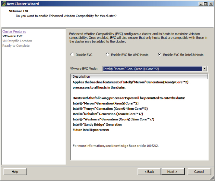
Configuring Enhanced vMotion Compatibility
Enhanced vMotion Compatibility (EVC) can be used in a cluster to allow greater vMotion compatibility for the different ESXi hosts in the cluster. Configuring EVC for a cluster allows the ESXi host processors to present a baseline processor feature set known as the EVC mode. The EVC mode will be equal to the host in the cluster that contains the smallest feature set.
Enabling EVC for a cluster is a simple operation, but it is important to know that the following requirements exist for enabling EVC on a cluster:
- All hosts in the cluster must have only Intel or only AMD processors. Mixing Intel and AMD processors is not allowed.
- ESX/ESXi 3.5 update 2 or newer is required for all hosts in the cluster.
- All hosts in the cluster must be connected to the vCenter Server that is used to manage the cluster.
- vMotion networking should be configured identically for all hosts in the cluster.
- CPU features, like hardware virtualization support (AMD-V or Intel VT) and AMD No eXecute (NX) or Intel eXecute Disable (XD), should be enabled consistently across all hosts in the cluster.
In Exercise 8.11, the steps to configure EVC on a cluster will be covered. In the interest of covering all lab environments, I will create a new cluster with no ESXi hosts for this exercise. This way, if you are using nested ESXi in your lab, you can complete the exercise. It will also allow me to cover how to enable EVC when the cluster is created.
At this point, a cluster has been created with EVC enabled. The remainder of this exercise will focus on the steps required to change the EVC mode.
In the previous exercise, there were no ESXi hosts in the cluster. This allowed flexibility in creating and changing the EVC mode. In the real world, where clusters will have hosts, it is important to understand how EVC mode impacts these hosts.
Lowering the EVC mode for a cluster involves moving from a greater feature set to a lower feature set. This is often useful when introducing ESXi hosts on newer hardware into an existing cluster. It is important to remember that any virtual machines running on ESXi hosts with newer features than the EVC mode supports will need to be powered off, before lowering the EVC mode.
Raising the EVC mode for a cluster involves moving from a lower feature set to a greater feature set. This is often useful when hardware refreshes of ESXi hosts have raised the CPU baseline capability. It is important to remember that any running virtual machines may continue to run during this operation. The VMs simply will not have access to the newer CPU features of the EVC mode until they have been powered off. Also note that a reboot will not suffice, and a full power cycle of the virtual machine is required.
The following two VMware KB articles are helpful for determining both EVC compatibility and processor support:
Now that I have covered configuring EVC mode for a cluster, I will cover how to monitor a DRS/HA cluster.
Monitoring a DRS/HA Cluster
There are many options for monitoring a DRS cluster, and having the vSphere Client open is a great start. If there are significant problems, the cluster item in the inventory will display an alert or warning icon. A warning condition is shown for a cluster in Figure 8.6.
Figure 8.6 Cluster with warning condition

In Figure 8.6 an ESXi host in the cluster was abruptly powered off to simulate a host failure. The cluster went into a warning status, and the ESXi host is listed with an alert status. This real-time information can be quite valuable.
A great deal of additional real-time information can be obtained about a cluster by simply viewing its Summary tab in the vSphere Client. Five panels are available on the Summary tab, and much of the information contained here is the same information found in the cluster settings properties window. Figure 8.7 shows the five panels available for viewing in the cluster Summary tab.
Figure 8.7 Cluster's Summary tab

The General panel shows the status of DRS and HA and the current EVC mode of the cluster. There is also information on the CPU, memory, and storage resources available to the cluster. Inventory information about hosts, processors, datastores, VMs, and vMotion operations are also available in the General panel.
Located under the General panel is the Commands panel, which provides convenient access to many of the same options available in the context menu for the cluster.
The vSphere HA panel is located on the top right and contains information on admission control and admission control policies. Host, VM, and application monitoring information are also available in this panel. At the bottom of the vSphere HA panel, there are two blue links provided for the cluster status and configuration issues. Figure 8.8 shows the vSphere HA Cluster Status window.
Figure 8.8 vSphere HA Cluster Status window
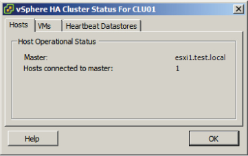
The vSphere HA Cluster Status window defaults to the Hosts tab, where the master node is identified and the number of slave nodes connected to the master node are listed. The VMs tab provides information on the number of VMs protected and unprotected by vSphere HA. The Heartbeat Datastores tab provides information on the datastores used for heartbeating.
The other blue link provided in the vSphere HA panel is to identify configuration issues in the cluster. Clicking this link will open the Cluster Configuration Issues window, where any problems with the cluster will be listed.
The next panel is the vSphere DRS panel, which lists the automation level, DRS recommendations and faults, migration threshold setting, and load standard deviation information. There are also two blue links included in the vSphere DRS panel. The lowest blue link titled View DRS Troubleshooting Guide will launch the help file. The other blue link titled View Resource Distribution Chart is one of the more useful tools for monitoring your cluster's resource consumption. Figure 8.9 shows the DRS Resource Distribution window.
Figure 8.9 DRS Resource Distribution window

The default view in the DRS Resource Distribution window is for CPU resources. Using the gray % and MHz buttons at the top of the window will allow the view to be toggled between utilization views. Each ESXi host in the cluster will be listed in the left column, and each of the colored boxes represents either a single virtual machine or a group of what are essentially idle virtual machines. Green boxes are good to see here! The legend at the bottom of the window shows that green means 100 percent of the entitled resources are being delivered for the VM. Any other color means the VM is not receiving all of its entitled resources. By hovering the cursor over any of these colored boxes, you can obtain the name of the virtual machine and information about its current resource usage.
The memory settings for the cluster are also available in the DRS Resource Distribution window, and this view can be selected by clicking the gray Memory button at the top of the window. Figure 8.10 shows the memory view.
Figure 8.10 DRS memory utilization view
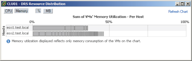
Using the gray % and MB buttons at the top of the window will allow the view to be toggled between utilization views. Each ESXi host in the cluster will be listed in the left column, and each of the gray boxes represents a single virtual machine. Just like with the CPU resources, hovering the cursor over any of these gray boxes will allow you to obtain the name of the virtual machine and information about its current resource usage.
As you can see, the information presented in the DRS Resource Distribution window provides a quick and easy way to see whether your hosts are load balanced and can often be revealing about which VMs are using the most resources. The information presented here also allows you to view more closely how DRS actually load balances.
Another option that can be used to monitor the cluster is the DRS tab that is visible when the cluster is selected in the left pane. The DRS tab default view of Recommendations lists the DRS properties and recommendations, if configured with either the partially automated or manual automation level. The Faults view can be used to view faults that prevented the application of a DRS recommendation. The final view is the History view, which can be used to review historical information for DRS actions.
The Resource Allocation tab, Performance tab, Tasks & Events tab, and Alarms tab can each also be used to monitor a cluster. Alarms can also be configured in vCenter Server to help monitor your cluster. Figure 8.11 shows the default vSphere HA alarm definitions.
Figure 8.11 vCenter alarms for vSphere HA
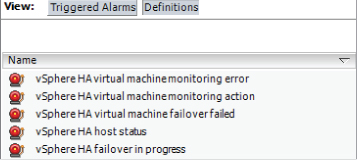
vCenter Server alarms will be covered in detail in Chapter 11, and many of the monitoring topics will also be revisited in Chapter 10 when troubleshooting HA/DRS clusters will be covered.
In addition to the included functionality in vCenter Server, there are additional options like VMware vCenter Operations or any number of third-party solutions that can be used to monitor your clusters. These products can provide additional insight into your virtual infrastructure and are often already deployed in many environments. Operational staff members are also typically trained in using these solutions. Leveraging these existing monitoring solutions can add additional monitoring capabilities for your DRS/HA clusters.
Now that I have covered monitoring a cluster, I will cover how to configure Storage DRS.
Configuring Storage DRS
Storage DRS is a new feature in vSphere 5. Storage DRS offers to datastores what a DRS-enabled cluster offers to ESXi hosts. When a virtual machine is deployed, it can be deployed into a cluster, and DRS will take care of the initial placement of the VM on an ESXi host. DRS can also move the virtual machine to a different host, as necessary, in order to provide the VM its entitled resources. Storage DRS provides both virtual machine placement and load balancing based on I/O and/or capacity. The goal of Storage DRS is to lessen the administrative effort involved with managing datastores by representing a pool of storage as a single resource.
![]()
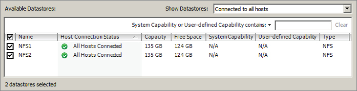
Storage DRS is made possible by the new datastore cluster object, which is simply a collection of datastores with shared resources and management. There are several requirements to use datastore clusters:
- Only ESXi 5 hosts can be attached to any of the datastores in a datastore cluster.
- Mixing NFS and VMFS datastores is not allowed in the same datastore cluster.
- A datastore cluster cannot contain datastores shared across multiple datacenters.
- VMware recommends as a best practice that datastores with hardware acceleration enabled not be used with datastores that do not have hardware acceleration enabled.
Configuring Storage DRS starts with creating a datastore cluster. Exercise 8.12 covers the steps to create a datastore cluster and configure Storage DRS.
The following image can be used as a reference for steps 9 to 14 of this exercise.
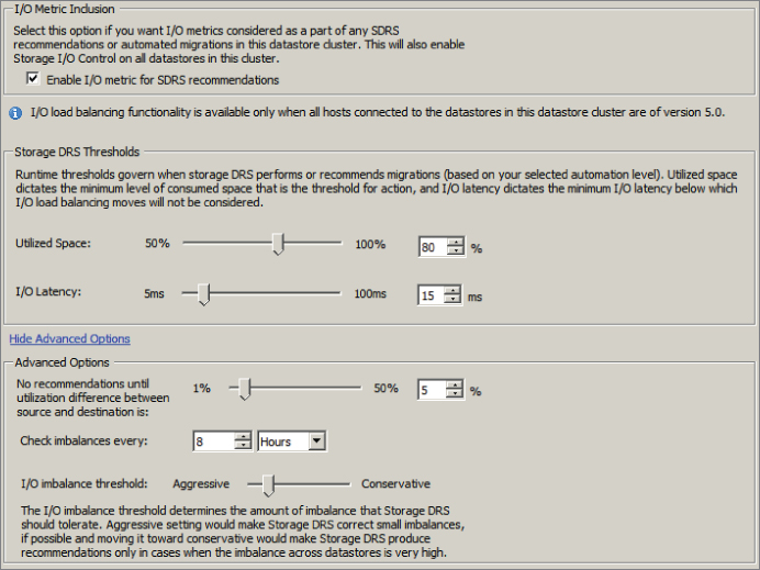
Enabling this option will allow vCenter Server to consider I/O metrics when making Storage DRS recommendations or automated migrations. In other words, this option enables I/O load balancing for the datastore cluster.
The Storage DRS thresholds are similar to the migration threshold setting used in DRS. A percentage of space utilization and a millisecond value of I/O latency can each be configured to trigger Storage DRS to make a recommendation or take an automated action.
This option is configured to ensure that a capacity-based recommendation is worthwhile. In other words, if the source datastore is 94 percent full and the target is 90 percent full, then don't make the move. The difference in these 2 percentages is the value 4. The default value of 5 percent would not allow this move to occur.
This setting is used to determine the frequency that Storage DRS will check capacity and load.
This setting is also similar to the migration threshold used in DRS. It is used to configure the amount of I/O imbalance that Storage DRS should tolerate.
You have now created a datastore cluster and enabled Storage DRS on it. This concludes the first section of this chapter on creating and configuring VMware clusters. In the next section, I will cover VMware Fault Tolerance.
Planning and Implementing VMware Fault Tolerance
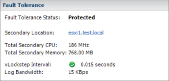
As a VMware Certified Professional, you will be expected to know when and how to use VMware Fault Tolerance (FT). FT is used to provide higher levels of virtual machine availability than what is possible with vSphere HA. VMware FT uses VMware vLockstep technology to provide a replica virtual machine running on a different ESXi host. In the event of an ESXi host failure, the replica virtual machine will become active with the entire state of the virtual machine preserved. In this section, I will cover use cases and requirements for VMware FT, as well as how to configure it.
Determining Use Cases for Enabling VMware Fault Tolerance on a Virtual Machine
VMware FT can provide very high availability for virtual machines, and it is important to understand which applications are candidates for using VMware FT. There are several use cases for VMware FT:
- Applications that require high availability, particularly applications that have long-lasting client connections that would be reset by a virtual machine restart.
- Applications that have no native capability for clustering.
- Applications that could be clustered but clustering solutions want to be avoided because their administrative and operational complexities.
- Applications that require protection for critical processes to complete. This is known as on-demand fault tolerance.
![]()
It is important to remember that VMware FT will not protect virtual machines from guest OS and/or application failures. If either the guest operating system or the applications running in the guest OS fail, then the secondary VM will fail identically. It is also important to note that VMware FT has both resource and licensing implications. If the primary VM uses 2GB of RAM, the secondary VM will also use 2GB of RAM, and both of these RAM allocations will count toward the vRAM total. Now that I have covered the use cases for enabling VMware FT on virtual machines, I will identify some of the requirements for using it.
Identifying VMware Fault Tolerance Requirements
The actual number of requirements to use VMware FT is rather large, and for the VCP exam it would be unreasonable to expect you to know all of them. For this section, only the requirements specifically listed in the vSphere Availability Guide have been included. There are many requirements for using VMware FT at the cluster, host, and virtual machine levels. For the cluster, these requirements include the following:
- Host certificate checking must be enabled in the vCenter Server settings.
- A minimum of two FT-certified ESXi hosts with the same FT version or host build number must be used.
- The ESXi hosts in the cluster must have access to the same datastores and networks.
- The ESXi hosts must have both Fault Tolerance logging and vMotion networking configured.
- vSphere HA must be enabled on the cluster.
In addition to the cluster requirements, the ESXi hosts have their own set of requirements:
- The ESXi hosts must have processors from an FT-compatible processor group.
- Enterprise or Enterprise Plus licensing must be in place.
- ESXi hosts must be certified for FT in the VMware HCL.
- ESXi hosts must have hardware virtualization (HV) enabled in the BIOS.
There are also requirements for the virtual machines that will be used with VMware FT:
- Eager zeroed thick provisioned virtual disks and RDMs in virtual compatibility mode must be used in the virtual machine.
- Virtual machines must be on shared storage.
- The guest OS installed on the virtual machine must be on the list of supported operating systems that can be used with VMware FT.
You should also note that only virtual machines with a single vCPU are compatible with Fault Tolerance. vSMP is not supported. Unsupported devices, such as USB devices, parallel ports, or serial ports, cannot be attached to the virtual machine; also, incompatible features such as snapshots, Storage vMotion, and linked clones must not be used on virtual machines that will be protected with VMware FT.
Now that I have covered the requirements to use VMware FT, I will move on to configuring networking for the fault tolerance logging traffic.
Configuring VMware Fault Tolerance Networking
To use VMware FT, there are two networking requirements that must be met. The first of these requirements is a vMotion network to be used by ESXi hosts in the cluster. vMotion is required, because the secondary VM is initially created by a vMotion of the primary VM to a different ESXi host in the cluster. Because of this design, it is also recommended to have separate 1GbE NICs for vMotion and fault tolerance logging traffic.
The fault tolerance logging traffic is the second network requirement for VMware FT. This is also a VMkernel connection type that is used to move all nondeterministic events from the primary VM to the secondary VM. Nondeterministic events include network and user input, asynchronous disk I/O, and CPU timer events. This is the connection that is used to keep the primary and secondary virtual machines in lockstep.
In Exercise 8.13, I will create a baseline networking setup that will include both vMotion and fault tolerance logging networking. This exercise will use a standard vSwitch and will require two available NICs in each ESXi host in the cluster. If you already have a vSwitch created for vMotion, you can omit the sections of this exercise that pertain to creating the vMotion network.

At this point, the new vSwitch contains a single port group that will be used for vMotion traffic. In the next part of this exercise, another NIC will be added to this vSwitch.

You have now added a second NIC to your vSwitch. In the next part of this exercise, I will show you how to add the fault tolerance logging port group to the vSwitch.
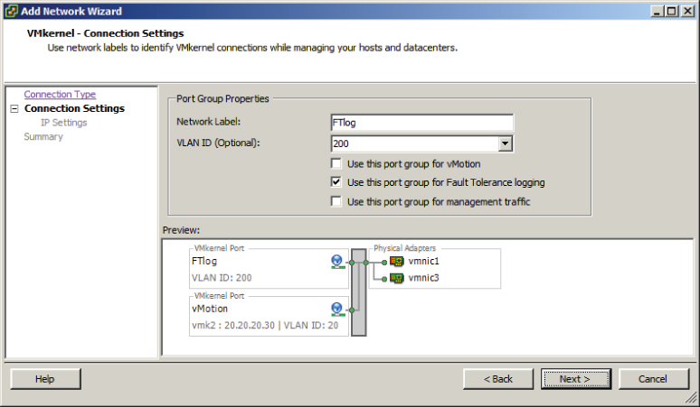
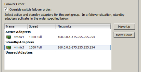
You have created a vSwitch with two physical uplinks and two port groups. The final configuration of the vSwitch will separate the port groups onto different vmnics. This will ensure that vMotion uses one physical uplink and that fault tolerance logging will use the other physical uplink. In the event that a single physical uplink associated with this vSwitch fails, this configuration will provide fault tolerance.

![]()
I have now covered configuring the network for fault tolerance logging to be used with VMware FT. Next I will show how to enable and disable VMware FT on a virtual machine.
Enabling and Disabling VMware Fault Tolerance on a Virtual Machine
Once all of the VMware FT prerequisites are met, the actual process of enabling FT for a virtual machine is incredibly simple. Exercise 8.14 covers the steps to enable FT for a virtual machine.

If the virtual disks were not in the thick provisioned eager zeroed format, the disks will need to be converted to the proper format before FT can be enabled. This disk conversion operation cannot be performed if the virtual machine is powered on. If the virtual disks in the virtual machine were already in the thick provisioned eager zeroed format, then the disk information would not have been present in the Turn On Fault Tolerance dialog.
Now that the steps to protect a VM with FT have been covered, I will cover the steps to disable FT for a VM that has been protected with it. Virtual machines protected with FT can have FT either disabled or turned off. Turning off FT for a VM will delete the secondary VM and all historical performance data. The virtual machine's DRS automation level will also be set at the cluster default settings. This option is used when FT will no longer be used for a virtual machine. Examples of this would be when a virtual machine has had its SLA modified or is due for scheduled maintenance and a snapshot is desired as part of the process.
Disabling FT for a VM will preserve the secondary VM, the configuration, and all historical performance data. Disabling FT would be used if VMware FT might be used again in the future for this virtual machine. An example of this would be when using on-demand fault tolerance for a virtual machine. Exercise 8.15 covers the steps to disable FT for a virtual machine that is currently protected with it.

At this point, the VM is no longer protected by FT. If there was a time where FT protection was again required, the following steps could be used to enable FT on the virtual machine.
Now that I have covered enabling and disabling VMware FT, I will cover the steps required to test an FT configuration.
Testing an FT Configuration
Now that FT has been configured and a virtual machine is being protected by it, the only remaining item is verifying that FT works as expected. The only way to know whether FT will work as expected is to test failover using the built-in functions in vCenter Server or to manually fail a host.
Testing via manually failing a host is easily accomplished. If your ESXi hosts are physical servers, then you could simply pull the power cable on the host that the FT primary VM is running on. If your ESXi hosts are virtual machines, then simply power off the ESXi host that the FT primary VM is running on. Either one of these approaches will guarantee an ESXi host failure. If you have many running virtual machines or simply aren't comfortable powering off your ESXi host this way, then you can also use the FT Test Failover functionality from the Fault Tolerance menu in the vSphere Client. This testing approach is preferred, since it is both fully supported and noninvasive. Exercise 8.16 will cover the steps to test your FT configuration.


Now that I have covered testing an FT configuration, the VMware FT coverage is complete. In the next section of this chapter, I will cover creating and administering resource pools.
Creating and Administering Resource Pools
As a VMware Certified Professional, resource pools are a topic you should be very familiar with. Resource pools are used to partition the CPU and memory resources of ESXi hosts. They offer a convenient way to separate resources along requirements or political boundaries and also offer a way to control the resource usage of multiple virtual machines at once. This offers significant advantages over setting individual virtual machine limits, reservations, and shares. In this section, I will cover how resource pools work and how to configure and use them.
Describing the Resource Pool Hierarchy
Each ESXi host or DRS-enabled cluster has a hidden root resource pool. This root resource pool is the basis for any hierarchy of shared resources that exist on stand-alone hosts or in DRS-enabled clusters. In Figure 8.12, the CLUSTER object represents the root resource pool.
Figure 8.12 Resource pool hierarchy

The root resource pool is hidden, since the resources of the ESXi host or cluster are consistent. Resource pools can contain child resource pools, vApps, virtual machines, or a combination of these objects. This allows for the creation of a hierarchy of shared resources. Objects created at the same level are called siblings. In Figure 8.12, RP-Finance and RP-Legal are siblings. Fin-VM1 and Fin-VM2 are also siblings.
When creating child resource pools below an existing resource pool, the resource pool at a higher level is called a parent resource pool. In Figure 8.12, RP-Legal is a parent resource pool for the child resource pool of RP-Legal-TEST.
Each resource pool can have shares, limits, and reservations specified, in addition to specifying whether the reservation is expandable. The Expandable Reservation parameter will now be defined.
Defining the Expandable Reservation Parameter
The Expandable Reservation parameter can be used to allow a child resource pool to request resources from its parent or ancestors if the child resource pool does not have the required resources. This allows greater flexibility when creating child resource pools. The expandable reservation is best shown in action, so Exercise 8.17 will demonstrate how the expandable reservation works.

The parent resource pool has been created with a 1000MHz reservation, and the Expandable Reservation parameter was not selected. This setting creates a parent resource pool that has a static 1000MHz of CPU resources. In the following steps, a child resource pool will be created.
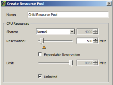
The child resource pool has been created with a 500MHz reservation, and the Expandable Reservation parameter was not selected. This setting creates a resource pool that has a static 500MHz of CPU resources. In the following steps, a VM will be created and powered on.
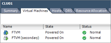
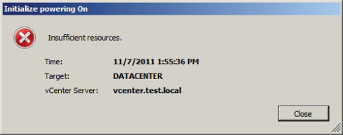
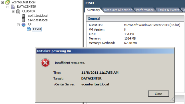
You should be presented with the error shown here.
You should now be presented with a running virtual machine, as shown here.

The expandable reservation allowed Child Resource Pool to pull the required resources from Parent Resource Pool to satisfy the CPU reservation of the virtual machine.
Now that I have defined and discussed the Expandable Reservation parameter, I will cover the steps required to create a resource pool using the vSphere Web Client.
Creating and Removing a Resource Pool
As shown in Exercise 8.17, the actual task of creating resource pools is very simple. Options like the expandable reservation illustrate that the more difficult task is in understanding how resource pools work and how they will be used in your environment. Exercise 8.18 details the steps to create a resource pool using the vSphere Web Client.

In this exercise, two resource pools were created. Assume that the cluster used in this exercise had a combined 6GHz of CPU and 30GB of RAM. In periods of resource contention, the RP-Legal resource pool will receive 4GHz of CPU and 20GB of memory, while the RP-Finance resource pool will receive 2GHz of CPU and 10GB of memory. In periods of no resource contention, the expandable reservation allows either resource pool to have more resources.
The task to delete a resource pool is also very simple. Keep in mind the implications of deleting a resource pool when working with child resource pools. Any virtual machines that are in the resource pool will be moved automatically to the parent resource pool or the root resource pool. To delete a resource pool, right-click it in the vSphere Web Client and choose the Inventory ⇒ Remove option from the context menu. You will be prompted to remove the resource pool, as shown in Figure 8.13.
Figure 8.13 Remove Resource Pool prompt

Click the Yes button to remove the resource pool. A Delete Resource Pool task will begin. When this task completes, verify that any virtual machines in the resource pool were moved as expected.
Now that I have covered creating and removing resource pools, I will next cover how to configure resource pool attributes.
Configuring Resource Pool Attributes
Resource pools can be modified after their creation by configuring their attributes. This is useful in situations where the resource pool requirements have changed. The shares, reservation, and limit can each be modified for the resource pool. Shares, reservations, and limits were discussed in Chapter 7, but they will be reviewed again.
Resource pool shares can be specified with respect to the total resources of the parent resource pool. Sibling resource pools will share the parent's resource, based on their specified share values. Virtual machines in resource pools with the highest share values will be able to consume more resources in periods of resource contention on the ESXi host.
In addition to shares, reservations can be used to guarantee a minimum allocation of CPU and memory for the resource pool. This setting is used to claim a specific amount of the resource for the virtual machine so that these resources will always be available. Memory reservations can also be used to avoid overcommitment of physical memory resources.
Limits are used to set an upper bound for memory and CPU resources. This prevents a virtual machine in the resource pool from using more resources than specified. This setting is by default set to Unlimited for both CPU and memory. Using this setting will ensure that the virtual machine uses close to the vCPU and memory allocations it has been granted.
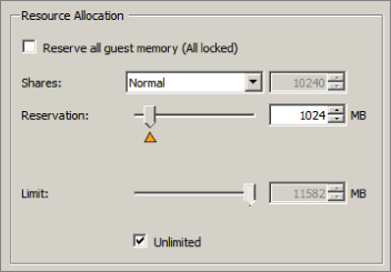
To edit a resource pool in the vSphere Client, right-click it and choose the Edit Settings option that appears in the context menu. The resource pool attributes will be shown and should look similar to what is shown in Figure 8.14.
Figure 8.14 Resource pool attributes

I have now covered how to configure resource pool attributes and will now cover how to add and remove virtual machines to/from a resource pool.
Adding and Removing Virtual Machines to/from a Resource Pool
Objects that can be added to a resource pool include other resource pools, vApps, and virtual machines. There are multiple options that can be used to add virtual machines to a resource pool. In Exercise 8.17, a virtual machine was added to a resource pool by right-clicking the resource pool and selecting the New Virtual Machine option from the context menu.
Virtual machines can also be added to resource pools, while powered on or off, by dragging and dropping them in the vSphere Client. Many virtual machine operations and tasks will also allow you to choose the resource pool as part of the operation. These operations include the following:
- Creating a new virtual machine at the host, cluster, or datacenter level
- Migrating a virtual machine using vMotion or cold migration
- Deploying OVF templates
- Cloning a virtual machine
- Deploying a VM from a template
- P2V conversions with VMware Converter
There are several caveats that must be covered for adding virtual machines to a resource pool:
- If the virtual machine is powered on and the resource pool does not have adequate resources to guarantee its reservations, admission control will not allow the move to complete.
- Virtual machine–configured reservations and limits will not change.
- Virtual machine shares of high, medium, or low will be adjusted to reflect the total number of shares in the new resource pool.
- Virtual machine shares configured with a custom value will retain the custom value. A warning will appear if a significant change in total share percentage would occur.
The operations that can be used to remove a virtual machine from a resource pool are similar to the operations for adding a virtual machine to a resource pool. Virtual machines can be dragged and dropped out of resource pools, while powered on or off, using the vSphere Client. vMotion, cold migrations, removing a virtual machine from inventory, and deleting a virtual machine are additional ways to remove it from a resource pool.
Now that the operations for adding and removing virtual machines to resource pools have been covered, I will cover how to determine the resource pool requirements for a given vSphere implementation.
Determining Resource Pool Requirements for a Given vSphere Implementation
Determining the resource pool requirements for a given vSphere implementation involves knowing or predicting what your environment will require for resources. The requirements will depend on a variety of factors:
- Knowing the characteristics and requirements of workloads or planned workloads
- Knowing the specific terms of SLAs or other agreements that dictate performance
- Knowing whether the resources will be divided along workload, business, or even political boundaries
- Knowing whether the applications would benefit from expandable reservations in resource pools
- Knowing who will own and administer the resource pools
- Knowing whether child resource pools will be created and used
- Knowing whether resource pools or the workloads running in them would benefit from using reservations or limits
- Knowing whether VMware DRS will be used and the vSphere editions (Enterprise and Enterprise Plus) required
- Knowing whether VMware HA will be used
- Knowing whether VMware FT will be used
This is not an all-inclusive list, and each implementation will be different. The key is to know the workloads, the infrastructure layout, licensing, and how the business or organization works. Political factors or budget control may determine the design in many cases, regardless of the technical factors.
Now that I have covered determining the resource pool requirements for a given vSphere implementation, I will move on to evaluating appropriate shares, reservations, and limits for a resource pool based on virtual machine workloads.
Evaluating Appropriate Shares, Reservations, and Limits for a Resource Pool Based on Virtual Machine Workloads
Much like determining the resource pool requirements, evaluating the appropriate settings really means knowing your workloads. In some cases, the workloads themselves may change or have new requirements. In Exercise 8.19, I will evaluate memory reservation settings for a virtual machine that has a new requirement of being protected with VMware FT.

You have now created the new resource pool that will be used for this exercise. The next step is to add a virtual machine to it.

You have now created a resource pool, added a virtual machine to it, and configured the reservation of the resource pool to allow the virtual machine to be powered on. Next FT will be enabled for this virtual machine.
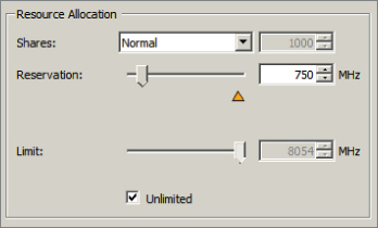
Enabling FT failed, because creating the secondary VM requires the same number of resources from the resource pool as the primary VM requires. The primary virtual machine was powered on, but the secondary was unable to be powered on because the lack of available resources. In the next steps of this exercise, I will adjust the resource pool memory reservation to account for this requirement.
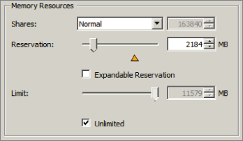
The insufficient resources error appeared again, because VMware FT has an additional overhead that ranges from 5 to 20 percent depending on the workload. You will now adjust the resource pool reservation to account for this 5 to 20 percent overhead. Note that adding 20 percent should guarantee success in the final steps of this exercise.


This exercise could be considered a review of the entire chapter, but its main purpose was to cover the steps to evaluate appropriate reservations for a resource pool based on a virtual machine workload. Next I will briefly review cloning a vApp.
Cloning a vApp
Cloning a vApp was discussed in Chapter 6, and Exercise 6.19 covered the steps necessary to clone a vApp using the Clone vApp Wizard. As a reminder, Figure 8.15 shows the Ready To Complete screen of this wizard.
Figure 8.15 Clone vApp Wizard

This concludes this chapter on clusters, FT, and resource pools.
Summary
The first part of this chapter focused on creating and configuring VMware clusters. This chapter began with determining the appropriate failover methodology and required resources for an HA implementation. DRS virtual machine entitlement was described, and I showed how to create and delete a cluster. I covered adding and removing ESXi hosts to/from a cluster, along with adding and removing virtual machines to/from the cluster. How to enable and disable host monitoring and how to configure admission control were covered. I covered virtual machine and application monitoring. Configuring automation levels for DRS and virtual machines was covered, along with configuring migration thresholds for DRS and individual virtual machines. I created VM-Host and VM-VM affinity rules. I discussed EVC and the steps to configure it. Monitoring a DRS/HA cluster was covered, and the first section concluded with configuring Storage DRS.
The second part of this chapter focused on planning and implementing VMware Fault Tolerance. Determining the use case for enabling VMware Fault Tolerance on a virtual machine was discussed first. I then moved on to identifying VMware Fault Tolerance requirements. Configuring VMware Fault Tolerance logging networking was covered. I enabled and disabled VMware Fault Tolerance on a virtual machine and concluded this section with testing FT configurations.
The final part of this chapter focused on creating and administering resource pools. This section began with describing the resource pool hierarchy. The Expandable Reservation parameter was discussed. Creating and removing resource pools were both covered, along with configuring resource pool attributes. I added and removed virtual machines to a resource pool and discussed determining the resource pool requirements for a given vSphere implementation. I covered evaluating appropriate shares, reservations, and limits for a resource pool based on virtual machine workloads, and I concluded this chapter with a review of cloning a vApp.
Exam Essentials
Review Questions
A. Enterprise or Enterprise Plus licensing must be in place.
B. ESXi hosts must be certified for FT in the VMware HCL.
C. ESXi hosts must have hardware Virtualization (HV) enabled in the BIOS.
D. ESXi hosts must have EVC mode enabled.
A. ESXi 4.1 and newer hosts are required.
B. ESXi 5 and newer hosts are required.
C. Mixing NFS and VMFS datastores is not allowed.
D. Mixing NFS and VMFS datastores is allowed.
A. The host must have host monitoring disabled.
B. The host must be in maintenance mode.
C. The host must be disconnected from vCenter Server.
D. None of these.
A. Single shared 1GbE NIC for vMotion and fault tolerance logging traffic
B. Single dedicated 1GbE NIC for fault tolerance logging traffic only
C. Isolating the fault tolerance logging traffic
D. Routing the fault tolerance logging traffic
A. It will shut down.
B. Nothing.
C. It will be powered off.
D. It will be suspended.
A. VM-Host affinity rule
B. VM-Host anti-affinity rule
C. VM-VM affinity rule
D. VM-VM anti-affinity rule
A. 5 to 10 percent
B. 10 percent
C. 5 to 20 percent
D. 20 percent
A. Priority scheduler
B. Global scheduler
C. Entitlement scheduler
D. Local scheduler
A. The Expandable Reservation parameter can be used to allow a child resource pool to request resources from its parent.
B. The Expandable Reservation parameter can be used to allow a child resource pool to request resources from its parent or ancestors.
C. The Expandable Reservation parameter can be used to allow a parent resource pool to request resources from its child.
D. The Expandable Reservation parameter can be used to allow a parent resource pool to request resources from a sibling.
A. Raising the EVC mode for cluster involves moving from a greater feature set to a lower feature set.
B. Raising the EVC mode for cluster involves moving from a lower feature set to a greater feature set.
C. Running virtual machines will need to be powered off during this operation.
D. Running virtual machines may continue to run during this operation.
A. The VM has an individual memory reservation set.
B. vMotion does not allow this operation.
C. Changing resource pools is not allowed.
D. No resource pools exist in the destination.
A. Manual
B. Partially automated
C. Fully automated
D. None of these
A. Host failures the cluster tolerates
B. Percentage of cluster resources reserved as failover spare capacity
C. Specify failover hosts
D. None of these
A. Shares
B. Reservation
C. Priority
D. Name
A. Failed
B. Unprotected
C. Isolated
D. Partitioned
A. The vSphere Client for the powered-on virtual machine
B. The vSphere Client for the powered-off virtual machine
C. The vSphere Web Client for the powered-on virtual machine
D. The vSphere Web Client for the powered-off virtual machine
A. Pull the power cables from an ESXi host that is running VMs with FT enabled.
B. Use the vSphere Client and right-click the secondary virtual machine. Choose the Delete From Disk option.
C. Put an ESXi host with FT VMs running on it in maintenance mode.
D. Use the vSphere Client and right-click a virtual machine that has FT enabled on it. Choose the Fault Tolerance Test Failover option from the context menu that appears.
A. Move the slider for the automation level to the far left in the DRS settings.
B. Move the slider for the migration threshold to the far left in the DRS settings.
C. Move the slider for the automation level to the far right in the DRS settings.
D. Move the slider for the migration threshold to the far right in the DRS settings.
A. Application that requires high availability
B. Application that has no native capability for clustering
C. Application that requires protection for critical processes to complete
D. Application that has persistent and long-standing connections
A. VMware FT
B. VM monitoring
C. Application monitoring
D. None of these