
Compositing in Vegas
What Is Compositing?
Compositing is the combination or interaction of two or more graphic or video images to create a single finished image. Compositing can be as simple as laying a title onto a visual image or as complex as combining hundreds of photographs, video, and animated elements to create complex images.
Compositing in its most complex forms is absolutely an art; there are compositing artists all over Hollywood, Austin, New York, Sydney, and other major cities who do nothing but create complex imagery for major networks, film, and corporate media departments. The fantastic imagery seen on ESPN, CNN, and in most major motion pictures is the result of these artists’ work. It is most likely that not one major motion picture has been released in the past few years that didn’t contain significant compositing, whether it’s titling, green/bluescreen work, or overlaid imagery. The Matrix is an amazing example of how greenscreen work is brought to the big screen through the creative use of composited images, as is the Lord of the Rings and even the heralded Titanic. Many of the full ship images in Titanic were composited together, including animations of people walking, driving, and loading the ship. Most of the scenes including fish are composited and animated. So in short, compositing is very much about eye candy and illusion.
Basic Compositing
Compositing in its most basic form is titles laid over images. Vegas has a fairly powerful titling toolset, capable of creating all but the most complex of titles.
To insert a title over an image, first place a visual event on the timeline. Right-click the Track Control pane and select Insert Video Track or select INSERT | VIDEO TRACK.
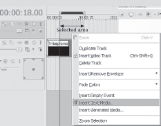
In the new video track, right-click the timeline and choose Insert Text Media from the menu.
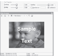
The Title tool opens with the Edit tab displayed, showing the words Sample Text inside. This area is where the words found in the title are inserted. Text size, font, and attributes, such as bold, italic, and justification are also selected here. These attributes and the Edit window work just like a word processor.
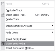
7.1 Right-click brings up this menu, then choose Insert Text Media to insert a title.
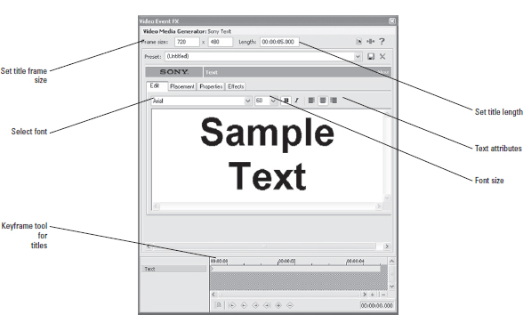
7.2 The Title tool with the Edit tab displayed.
Get your title to exact length the first time. Create a time selection in the project that is the desired length of the title. In the track where you’d like the title to live, right click and choose “Insert Text Media.” A title dialog will open up, set to the length of the selected area. This will override the default title lengths in the Options|Preferences|Editing dialog.
The frame size can be selected at the top of the titling tool. In Vegas, generated media always defaults to 720 × 480, (non-square pixels) but appears correct as to frame size. (If you are creating titles outside of Vegas for NTSC DV, the frame size should always be 655 × 480, and for PAL the frame size should always be 704 × 577.) This factor compensates for the non-square pixel aspect ratio of DV.
The media length is set by default to whatever the length of stills is set at in the OPTIONS | PREFERENCES | EDITING dialog; however, the length of the media can also be selected in the top of the Title tool, overriding this value.
Often, the setting in the Options menu is for stills, yet titles need to run longer. It’s speedy to extend a title by specifying a longer title in this dialog. Titles, of course, can be looped to any length. Presets are available in the titling menu. These presets are there to assist you in creating great titles out of the box, but for truly powerful and professional-looking titles, you need to learn the features of the rest of the titling tool.
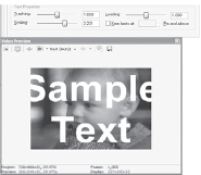
Titles can be positioned anywhere on the Text Placement dialog, which is under the Placement tab.
To manually place a title, click the text in the window of the Edit tab and then drag the title to the desired location. By default, a safe area is defined at 10 percent. This safe area indicates the area in which a title should live if it’s being shown on television. Televisions have an area that is partially covered by a bezel in addition to being unscanned. This area hides approximately 10 percent of the video signal. Some televisions cover more and others less. The safe zone can be defined from a zero size area to a 30 percent safe area, by clicking in the Safe Zone text box and entering the desired safe area size. Ten percent is a typical safe area for NTSC and PAL video. Streamed media requires no safe area.
Title placement can be keyframed if the title should move onscreen.
Title Properties
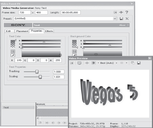
Under the Properties tab, the color, tracking, scaling, and leading of the title can be controlled. Selecting the color is done by placing the cursor in the color palette and clicking. The cursor changes to a small target icon that can be dragged inside the color selector.
If a specific color is desired, the RGB values of the specific color can be entered into the color value boxes. Vegas also offers a color picker, which allows you to use the Eyedropper tool to select a color or range of averaged color.
The Eyedropper tool can be applied to any image on the screen. If a commercial color set is available, exacting color selection is possible.
Color can also be selected based on hue, saturation, and luminance (HSL) by selecting the HSL button just above the Eyedropper tool.
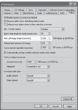
7.4 The Editing tab found in the OPTIONS | PREFERENCES dialog allows users to preset title and still default lengths.
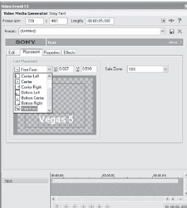
7.5 Titles can be manually placed anywhere, or presets can be used to place a title.
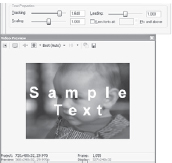
A background color can be specified if necessary. If the title is overlaid on a video image, a background color probably shouldn’t be specified and should be left transparent instead. This feature can be used as an effect over video, and if the opacity of the background color is reduced, the visual image will show through the color, causing the background color to act as a color filter. All color aspects are keyframe-controllable.
The Text Properties area of the Properties tab in the Title tool allows for adjustment of the kerning, leading, and spacing of text. By default, auto-kerning is disabled. Check the button to enable it.
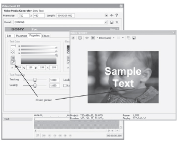
7.6 Using the Eyedropper to match the color title to the flower on the shirt
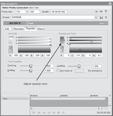
7.7 Selecting a background color’s transparency/opacity.
Tracking controls the distance between letters in the text/title field. Leading controls the space between two lines. Leading fine-tunes a single line of text up and down. Scaling controls the sizing of the letters. All three text controls are keyframable. Scaling tends to be jerky in the scaling of text, so use with caution.
A check box is available for automatic kerning of letters above a preset, user-controlled size. Kerning is the specific spacing between a pair of characters. Some letters take up more space than others, and without kerning, sometimes letters appear to be too far apart in a word. Kerning generally alleviates this problem, although some fonts use more space than others.
Adding Effects to Text
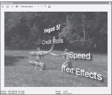
The Effects tab offers a number of options to edit and enhance text. Effects often are used to make text stand out on otherwise busy visual screens or to create a specific mood.
Adding a glow to text can make letters show up when the underlying media is of a similar color. Glow is also often used to give text an image of depth, such as coming out of a vacuum.
Clicking the Draw Outline check box adds a glow to the text. This effect is great for outlining light-colored text with a slightly darker color, creating a slight illusion of 3D.
7.8 The tracking control.
7.9 The leading control.
7.10 The scaling controls.
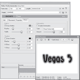
7.11 Using Outline to create a glow around text causes the text to stand out.
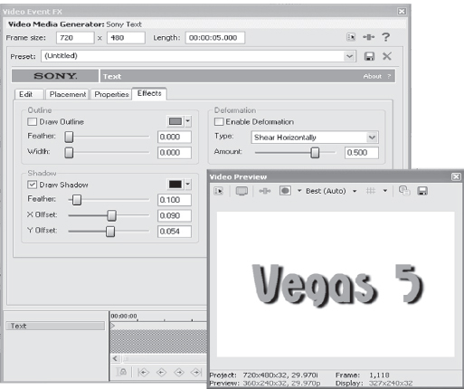
7.12 Adding a shadow adds depth and dimension to text.
The outline can be feathered, which smoothes out the transition between the text and underlying media and softens the edge of the glow. Use this effect to add a bit of flair to text that might otherwise be dull.
Drop shadow, or shadowing, is one of the most useful tools in the Effects tab. Click the Draw Shadow check box, and a shadow will appear beneath text. This shadow can be colored in any color found in the palette by clicking the Color button and then selecting either a preset color or choosing a custom color by using the color picker/eyedropper to select a color.
Shadows can be keyframed to add depth to a title, moving in a direction opposite the original text, which creates an image popular in Hollywood titles today. Colors and opacity can be keyframed and combined with glow to create very rich and deep title attributes. Feathering smoothes and softens the edges of shadows and adds perspective to the depth of the text.
The Deform tool can shear, bend, squish, or compress text. Text can be wrapped around images by curving, or text can be used to give the impression of urgency by keyframing a fast bend as the text comes on or off the screen.
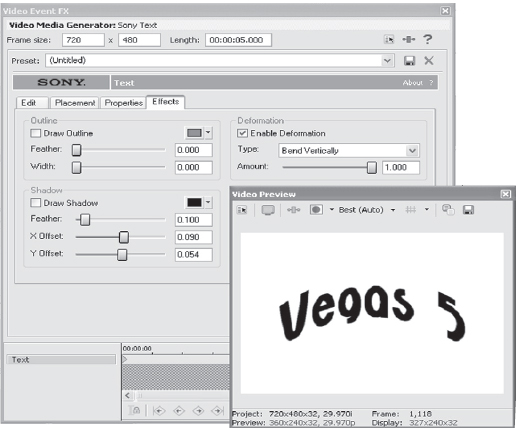
7.13 Bending text around an image can create an illusion of text and image being one image.
You can keyframe text with any one of the many effects in the tab and create flowing text that appears to be very deep, particularly when combined with other text effects.
Each of the three effect sections has slider controls for different text features. Double-clicking a slider returns the slider to its default “null” position. Clicking on the slider activates the effect, and the control can be controlled either with the mouse, or if active, can be moved with the Right Arrow and Left Arrow keys for more precise control.
Learning to manipulate titles is an introduction to compositing, and titles are one of the most creative and yet difficult aspects of film and video production. In the past, complex applications were required to do in-depth titling, while today Vegas contains many of the same tools as the more complex tools offered in the past. With some creativity and inspiration, Vegas can be use to create Hollywood-level titles. In fact, many Hollywood-level films and television productions contain title work created in Vegas.
7.14 Inserting a mix of effects can create complex titles.
Using the Pan/Crop Tool
![]()
Vegas has a Pan/Crop tool that can be used on any video event. This powerful tool can be used to correct camera depth, create motion on a still image, match aspect ratio, or crop out unwanted material from an image. While simple in use, this tool is exremely powerful.
Open the Pan - Crop.veg project so you can follow along visually with this section.
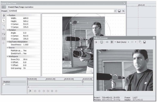
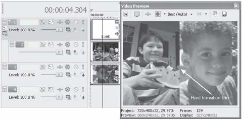
After capturing video and placing it on the timeline, each clip will contain a small Crop symbol. Notice that in Figure 7.14 the image in the monitor screen does not entirely fill the video preview area. Clicking the Crop tool opens a dialog that allows the user to entirely fill the Preview screen and match the image view to the aspect ratio of the Preview screen.
This feature is particularly useful when creating videos of scanned-in still photos or cropping unwanted content from a video image. See Chapter 4 for details on photo sizes and scanning.
With the Crop dialog open, right-click the image inside the Crop window and select ate Output Aspect.
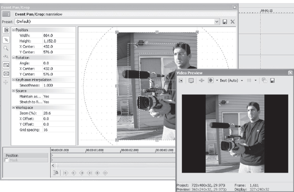
7.15 The photo does not fill the entire Preview window.
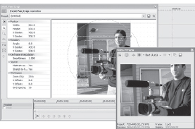
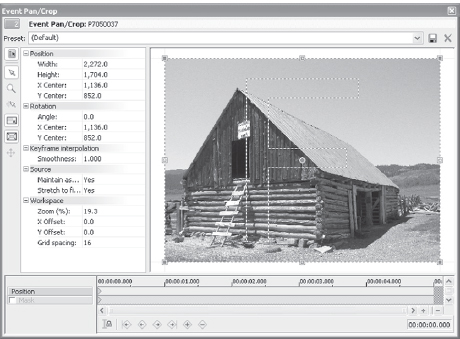
7.16 Selecting the project aspact ratio crop too much of the image out in some instances.
This action causes the image to be cropped to a size that will completely fill the preview area. Now, the Preview window is completely filled with no black background showing. The aspect ratio of the photo, however, appears to be correct even if the photo itself really isn’t. This aspect ensures that all imagery mixed with DV and other graphics can be made to fill the viewing screen completely at all times, matching the aspect ratio of the project. This accomplishment, however, isn’t without its specific issues. For example, we no longer can see the entire image that comprises the photograph shown in Figure 7.15. Notice that the gramophone has lost the overall view in Figure 7.16. The viewer can now see only the part of the gramophone that the editor allows them to see—useful in some situations, but not in others.
Wouldn’t it be great if the still image could move, almost as though a camera had been used to capture the image rather than a scanner?
We can create that movement by the use of keyframes. Right-click again and select the Pan/Crop tool or click the Crop tool icon found on every clip or image on the timeline. Now, move the Selection/Crop window to a new position. The Keyframe tool automatically inserts a keyframe, telling the timeline that at a specified time, the photograph should be cropped differently. Zoom in on the photo and zoom out of the photo, placing keyframes at each point of movement. Notice the added keyframes in Figure 7.17.
Producers of PBS specials, BBC documentaries, wedding videos, and broadcasts apply this same technique to create the illusion of movement. Even if the image is exactly the correct aspect ratio, no one really likes looking at a static photo on a computer or television screen. Even the smallest bits of movement are far more interesting to watch than a static photo.
In the past, tracking cameras, or remote control-operated cameras that mount on a rail, shooting motion images over a still photo, have been used to create this effect. Ric Burns, celebrated filmmaker/documentary genius of The Civil War, The Way West, New York, and others, has employed still images coupled with motion to change the entire face of documentaries. This effect can now be easily accomplished with a scanner and the Pan/Crop tool. This tool is tremendously powerful and useful for putting together slide shows, wedding montages, or other photo-heavy presentations.
Another application uses the Pan/Crop tool to correct bad camera movement. It can also be used to generate camera movement where the camera is static or not moving at all. If the clip of a soccer game, for example, is tripod-shot and static the camera movement could be generated to tell the viewer where they should be looking. A word of caution: don’t zoom in too far, or the pixels will become too large and the detail of the event will wash out. This tool should be used in a subtle way for video. It’s a terrific precursor to a transition.
Still images can usually handle deeper zooms if the resolution is set high enough on the original photo. Typical sizes of photos generally are considered best at 72 dpi for video; in most cases, saving photos at double the standard resolution provides a clean image for zooming and panning. However, preview stills in your scanning software to ensure the best resolution for your needs.
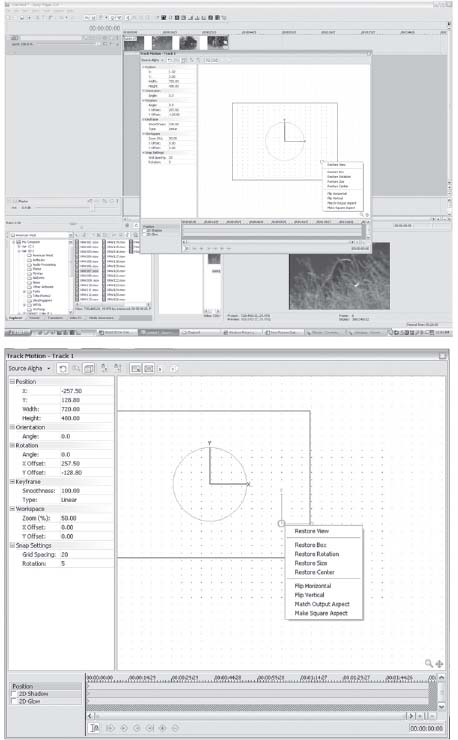
In addition to the Match Output Aspect menu in the right-click dialog, additional choices include the following:
• Restore—restores pan/crop boundaries to the edges of the image. No pan/crop takes place.
• Center—centers pan/crop boundaries around the centering dot found in the middle of the crop boundaries.
• Flip Horizontal—flips images horizontally, making the right side become the left side. (This feature is great for changing a view. Open multicamera.veg for more information.)
• Flip Vertical—flips images vertically, causing most images to be upside down.
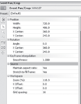
• Match Output Aspect—matches the image aspect ratio to the settings in the FILE | PROPERTIES dialog, which is usually 720 × 480 for DV editing.
• Match Source Aspect—matches the image aspect to the original aspect ratio. Use this setting when applying full photos over other montages and when it is acceptable for the photo’s borders to be seen. This feature will still allow an image to be resized smaller; however, the aspect ratio is that of the original image, not of the project.
7.17 Notice the key frames created to build the illusion of a camera-shot still photo
![]() Tip
Tip
Having photos at too high a resolution creates artifacts on the video image, containing too much information for a video image.
Standard-size graphic images, such as titles, backgrounds, and generated graphics, should be created at no higher than 300 dpi, or double the maximum zoom, and should be sized at 655 × 480 for insertion into a DV project. This configuration compensates for the non-square pixel issues found in DV. Always reduce interlace flicker for photos and consider using the Broadcast colors filter on stills if they are beyond legal colors. The Broadcast filter can be dropped directly on a still image event, or if the timeline contains a large number of stills, the filter can be dropped on the Project window instead. Instead of a Broadcast filter, you might want to try a Levels filter, set to convert Computer RGB to Studio RGB. Set this by reversing the Studio RGB to Computer RGB settings, which will ensure that the entire dynamic range is passed. (See Chapter 8 for more information on legal colors.)
The Pan/Crop tool can also be used to create 3D–like imagery. By spinning an image, whether video, photo, or graphic, the illusion of 3D can be created by adding a glow or shadow to the image. Of course, with the 3D Track Motion tols, this merely becomes an added bonus.
In the second section of the Pan-crop.veg project, a flip or rotation is found on the project. Glow, shadow, and keyframed motion of the pan/crop is applied to the image.
Use the Pan/Crop tool to flip images horizontally, vertically, or to squeeze an image onto the screen. Partnered with the Spherize plug-in found in Vegas, this process is one means of creating unique titles or animations of transitioning video.
Masking with the Pan/Crop Tool
Like the Track Motion tool, the Panning and Cropping tools have undergone a significant face lift. Users of earlier versions of Vegas will find the new tools to have a slight learning curve, but once understood, the power of this new toolset in the Pan/Crop tool is fabulous.
If the Pan/Crop icon isn’t visible on each video event, go to Options>Preferences>Show Video Event Buttons, and tick the check box there. This will cause the Pan/Crop and FX buttons to be visible on each media event. If you are working with single-frame events, you may want to turn this feature off. You can always access Pan/Crop and FX by right-clicking any video event.
Place a video event on the timeline. This can be a generated media event or a video event. Insert the Pan/Crop tool by selecting the Pan/Crop icon found on the event or right-clicking the event and choosing Pan/Crop
7.18 The Pan/Crop tool in Vegas 5 and 6 is different compared to earlier versions of Vegas.
For users of previous versions of Vegas, notice that the familiar interface has changed significantly. Rather than a series of dialogs with dropdown menus, the new tool is slider-based. A parameter is chosen, and the slider used to set the parameter. For example, notice the Zoom option. Click the word Zoom, and the slider next to the parameter lights up. This allows you to zoom more deeply on the image in the Pan/Crop window, and work at fine detail levels without the Pan/Crop preview window requiring a shift in size as it did in previous versions of Vegas. I find that setting this to a level of 50 is a good starting point for most Pan/Crop motion work. As with all of the Sony tools, double-clicking the parameter slider or button resets this to the default. The default setting for the Pan/Crop tool is 100, which may prove to be too large for some work spaces.
The Pan/Crop tool still may be manually moved in the workspace as in previous versions of Vegas, and values may be inserted with the keyboard as previously possible. But the slider tool found in this latest revision may prove to be more creative or intuitive for some users. I find that I grew used to it very quickly and find it a great way of getting my images to position or size very quickly.
Open the Pan/Crop tool the way you usually do, and you’ll see a new control in the Pan/Crop keyframing tool labeled “Mask.” The Mask allows bezier curves to be drawn in the Pan/Crop tool as masks, opening up an entirely new creative realm.
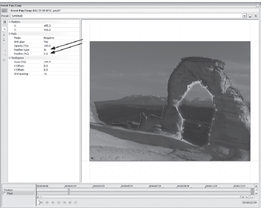
Click the Masks indicator so that Masks is selected in the keyframe tool. Now hold down the Ctrl button, and this will cause the cursor to turn to a pen tool in the Pan/Crop preview window. Left-clicking the pen tool in the Pan/Crop Preview window will insert a point in the window. Now move the cursor to a new location, hold Ctrl, and left-click again. This will create yet another point in the Pan/Crop preview window. Create at least three points, joining one to another. As the pen tool is rolled over the first point in the mask, a small circle will appear, and all mask points will turn yellow, indicating that the mask is a completed path. A selection is now made. Pressing the Alt key and clicking on any of the yellow anchor points will select all anchor points. Clicking on any single anchor point allows it to be selected and the Bezier curve to be adjusted to work with the angle or curve you’d like to create. These curves and selected areas are completely keyframe controlled, so this sort of selection may move with any object or subject that you might have in the video image. Multiple selections may be made in the Pan/Crop window, allowing for multiple objects and selections to be cut out and defined.
7.19 Closeup view of the Pan/Crop tool with all tools expanded.
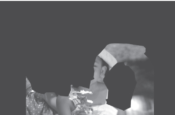
On the left side of the Pan/Crop tool, you’ll find a new interface and control set. In this control set is a setting labeled “Path.” Click on the Path Mode dialog or on the + symbol next to the word “Path,” and a drop down menu appears with the choices “Positive” and “Negative.” When Positive is chosen, the area inside the curve is visible and the remaining space is transparent. When the Negative option is chosen, the area inside the curve is transparent, and the area outside the anchor points and path is visible. This is a great tool for removing a subject from a background, placing them in a new background, or removing a background from a current scene and replacing it. One way to consider this tool is that it’s like a Chromakey tool that will work regardless of the number of colors found in the background. At many levels, this feature brings some of the tools found in rotoscoping tools to Vegas.
The opacity of the mask may also be controlled via the new Pan/Crop Bezier tool. Opacity, like all other aspects of the Bezier tool, is keyframe-controlled. One benefit is that masks may be faded in or out over time by using the keyframe tool to create the type of image needed to complete the composite or overlay.
Open the Path dialog by clicking the + symbol next to the word “Path.” Note the Opacity parameter in the Path dialog.
Opacity may be controlled by entering a value via the keyboard, sliding the Opacity slider, or using the spinner controls next to the slider tool. Use the Page Up and Page Down arrows for coarse control, moving the value in increments of + or –10, and use the Up and Down arrows for fine control moving in fractional values. For example, setting the first keyframe in the masking timeline to a value of zero causes the mask to be transparent, or invisible. Setting the next keyframe to a value of 100 will cause the mask to be completely opaque. This may be used to fade the mask in or out of the image composition.
Values in the Pan/Crop and Track Motion dialogs may be controlled by the keyboard or programmed HUI device. Use the Page Up and Page Down keys for coarse control of parameters in these two dialogs. This shifts the value in increments of + or –10. Using the Up or Down arrows shifts values by single-digit increments. You can also use the Tab key to scroll downward through the attributes of the dialogs and use Shift+Tab to scroll upwards.
Next in the list of power tools found in the new Pan/Crop tool is the Feathering tool. This allows you to blend the masking lines created in the Bezier mask with the background. When working with moving media, this is exceptionally helpful as it can assist in blending moving images against a moving backdrop.
7.20 Use Feathering in the Pan/Crop tool’s masking toolset to blend the mask with the background if the lines seem too visible. Feathering may be either inside, outside, or in both directions from the mask line.
Feathering can take place either inside the mask, outside the mask, or in both directions.
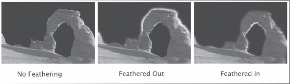
7.21 Three examples of feathering with the Bezier masking tool.
To take advantage of the Feathering tool, first create a mask as described above. Open the Path dialog by clicking the +symbol next to the word “Path.” Note the feathering dialog beneath Opacity.
Choose how you’d like the path feathered. Experiment with all three feathering modes to determine what works best for the mask.
Masks created in the Pan/Crop tool may be copied and pasted to other events. The most common method to copy or paste a mask is to copy an event containing a mask contained in the Pan/Crop tool, right click on the destination event or video clip, and select Paste Attributes from the submenu that appears. However, if the destination image is of a different size or aspect ratio from the original, this will not apply the mask correctly in the destination image, as Vegas will interpolate the position based on the value of the source image. For example, if a mask has been created by drawing points around a .jpg image and the mask is copied or pasted to an .avi file of a different size, the mask will not paste in the same location or aspect as created in the source .jpg. The correct method of copying and pasting a mask attribute from differing file types is to copy the keyframes from the source image and paste them into the keyframe timeline of the destination image. This will ensure correct aspect and location.
7.22 To copy mask attributes from a source image that is different in size or aspect from the destination image, copy the keyframes from the source image rather than using the more common copy and paste attributes. This will ensure that regardless of the aspect ratio of the image being pasted to, the aspect of the mask will remain correct rather than scaling to fit the aspect of the new image.
On each video track, Vegas assigns a Track Motion tool. This tool is exceptionally powerful and goes far beyond its initial impressions.
The Track Motion tool in its most basic form can be used to create a picture-in-picture presentation,
allowing one motion video event to be placed over another motion video event while reducing the size of either event and alowig bth images to be visible simultaneously.
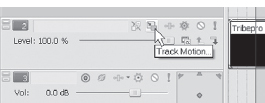
7.23 The Track Motion button is found on every video track in Vegas.
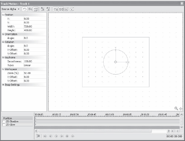
7.24 The Track Motion dialog has many choices with which to manipulate an image.
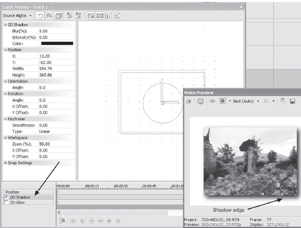
7.25 A shadow applied with the Track Motion tool.
Clicking the Track Motion button opens a dialog that is similar to the Pan/Crop dialog. In fact, these two tools share many of the same attributes but accomplish completely different tasks.
As an example, a shadow can be applied with the Track Motion tool, as shown in Figure 7.25. Shadow can be applied to any image with the Track Motion tool, even if the resize or motion features of the tool are not used. This fact will be useful when using text as masks as shown later in this section. It’s also a simple task to apply shadow to a still image or graphics with a transparency by using this tool.
Starting with the top-left corner, a number of tools are found within the Track Motion dialog. The Show Properties button hides and shows the position, angle, zoom, and other views found on the left side of the Track Motion tool. The Normal Edit button, just below the Show Properties button, is the tool predominantly used to size, rotate, and manipulate the images in the track motion frame window.
The Zoom tool, which looks like a magnifying glass, allows for tight zooming on the frame window area and is very helpful when trying to align images in the frame to a small grid space or when creating exacting keyframes.
Enabling Snapping causes the frame in the Track Motion tool to be snapped to the nearest grid and is also useful for accurately locating the frame during editing.
The Lock Aspect Ratio in the Track Motion tool functions in the same way as the Pan/Crop tool. Unlike the Pan/Crop tool, however, the Track Motion tool causes the frame in the Preview-windo to rmai in he correct aspect ratio, but size-reduced.
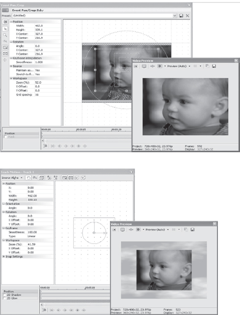
7.26, 7.27 Similar settings in the Pan/Crop tool (a) and Track Motion tool (b) frame windows, but very different results in the Preview window. Try inserting a Border filter with the Soft Edge preset on this sort of composited shot.
The Lock Aspect Ratio function should be used in most operations of Vegas so that the vertical and horizontal aspects of the image remain equal. The aspect ratio, however, can often be used as part of a creative edit. Turning off aspect ratio and adjusting generated media, for instance, is great for creating lines or other shapes. (Generated media is discussed later in this chapter.) By default, these buttons should be enabled.
The Size At Center button found on the top side of the Track Motion tool to the right of the Lock Aspect Ratio causes the frame and subsequent view in the Preview window to center around the dot found in the middle of the track motion frame. When you move the dot to another location, right-click, and then choose Center while this button is enabled, the dot will return to the center of the track motion frame. In addition, the frame image will move with it while keeping the dot where it was moved in relation to the original center of the frame. The center dot is actually designed to move a frame off center during movement, providing a pivot point for rotation of the frame.
Sizing a frame down to one-fourth screen and snapping at the centerline causes the frame to be part of a quad image on a screen. Figure 7.28 shows three images reduced in size and snapped to centerlines of grid. The gradient is generated media with a title overlaid.
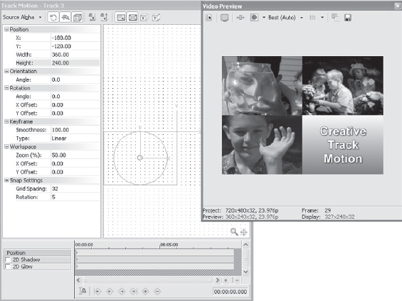
7.28 Three images reduced in size and snapped to grid.
7.29 Note that in Vegas 6, the Track Motion presets that had been removed in Vegas 5 have returned. Users can now specify presets for Track Motion.
Track motion is where most users become acquainted with the concept of deeper compositing, as opposed to just creating titles overlaid on images. Another common use of track motion is to create a picture-in-picture image. Creating a picture-in-picture is fairly simple and is a good exercise for getting started with manipulating images.
To create a picture-in-picture image, create two tracks of video, with events on both tracks. Place the cursor in the middle of the two events.
Track 1 is the overlaid event that will become the picture-in-the-picture. Select the Track Motion button on track 1.
Make sure Lock Aspect Ratio is enabled, grab the lower-right edge of the frame in the track motion frame view, and reduce in size, watching the Preview window as the frame and preview image are reduced. Reduce the track 1 event to the size of × + 317.0, y = 210.0. (Size is displayed near the cursor during resize or can be directly input in the Track Motion Properties dialog.)
In the Properties Center dialog, input a value of 180 for the left box and a value of 120 for the right box. These settings will place the video slightly to the right of extreme left and slightly below the top of the screen.
Preview the image by pressing W (rewind) and the Spacebar (play).
The track 1 event will be previewed in the upper-left corner, while playing over the top of track 2’s event. If both tracks are video tracks, full motion will be seen in both events.
7.30 Picture-in-picture images are very fast to create with Track Motion.
Be sure that the Sync Cursor button is disabled when working with this exercise unless the desired effect is to shrink the track 1 event to the proscribed size. Otherwise, the first keyframe, which in most cases will be a full frame view of track 1, will gradually shrink the track 1 event until it reaches the second/new keyframe generated by shrinking. It is easy to accidentally create unwanted keyframes during the track motion or pan/crop actions. In the event of a second keyframe being created in the Track Motion dialog, right-click the first keyframe found in the keyframe dialog and select Delete from the menu. This step will then cause the second keyframe to be the initial size of the event. You will quickly create a workflow based around your personal preference for managing these two tools.
The picture-in-picture image might seem flat or without dimension, as the two images are at exactly the same depth of field. To create a depth of field, insert a shadow.
Shadows can be inserted in any color, opacity, and size within Vegas. Open the Track Motion dialog again by clicking the Track Motion button on track 1. A check box for a shadow is located at the bottom of the dialog on the left side of the keyframe timeline. Checking this box adds a shadow to the frame in the Preview window. One of the more creative uses of the Shadow tool is to turn off the aspect ratio of the Track Motion tool when applying shadowing and to create shadows that stretch, move, shrink, or rotate while the image that the shadow falls from remains in aspect ratio. To disable aspect ratio on the shadow, which is enabled by default, press Ctrl while moving the shadow about the screen. To disable it for the duration of the editing process, click the Lock Aspect Ratio button, turning this tool off. If the image on the timeline has an alpha channel, the shadow will work with the opaque image. This method is one way to create layered shadows under PNG, TGA, GIF, AVI, or other alpha-capable image formats. Shadows are keyframable for opacity, color, size, and position.
7.31 Shadow applied to PNG file containing alpha channel.
7.32 Glow can be subtle.
7.33 Glow can be exaggerated.
Glow may also be applied to images in the frame. Glow on its own, or combined with shadowing, allows for very complex image manipulation. Glow is adjustable in opacity, color, and size. Glow can also be feathered to blend into background or other composited images.
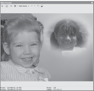
Using glow in a subtle manner around letters whose color properties closely match a background color can help offset the letters from the image underneath. Glow is keyframable for opacity, color, size, and position and can be used in a similar way to a shadow in that it can have a separate path from the image to which it is assigned. Using a combination of glow and shadow allows for two separate moving images beneath a single event.
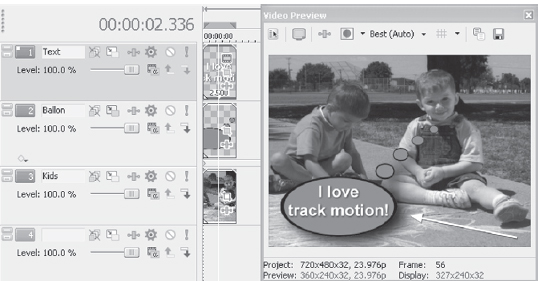
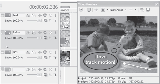
The project seen in Figure 7.34 is on the DVD in this book, labeled compositel.veg. This project can be used as a template.
The Track Motion tool can be applied to just about any project in some form or fashion, splitting screens, creating multiple screens such as seen in the opening f the Brady Bunch television series, used to fly titles in or out and any number of other creative uses.
![]()
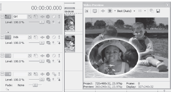
The project displayed in Figure 7.36 can be found on the DVD in this book and is labeled composite2.veg.
7.34 Glow combined with a mask and shadow makes for a seamless transition between the foreground and background events.
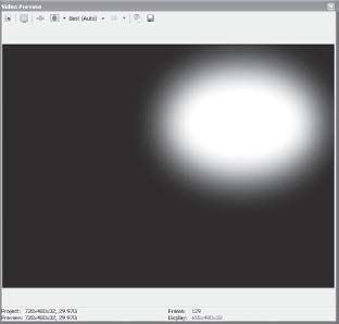
7.35 Mask soloed to demonstrate the cookie cutter, blur, glow, and shadow combined.
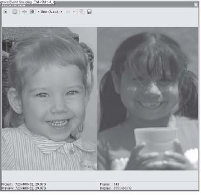
7.36 The split screen is achieved quickly with the Track Motion tool.
The Next Dimension: 3D Track Motion Tools
Vegas 5 and 6 take a great leap into the next level of creative power by offering a few 3D creative tools. If you’ve worked with the Plugn’Pak from Debugmode for Vegas 3 or 4, then you are more or less familiar with how this tool is going to work for you, however the new feature is embedded in the Track Motion tool. Access to all planes of movement may be keyframed from within the Track Motion tool.
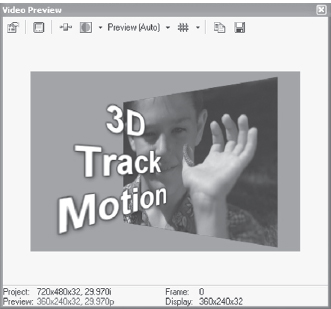
7.37 The new 3D feature is great to use with text to create alternate planes and angles for text.
The new Track Motion tool featureset will be unfamiliar to previous users of Vegas, as it marks a departure from the interface that users are familiar with. However, in order to accomplish some of the features now found in Vegas, these changes were clearly necessary.
To get started with the new Track Motion tool, create a new video track and drop a video event on the new track.
Select the Track Motion button on the track header.
A new dialog opens up, showing the new Track Motion appearance. (If you are new to Vegas 5 and 6, this will not be new to you.)
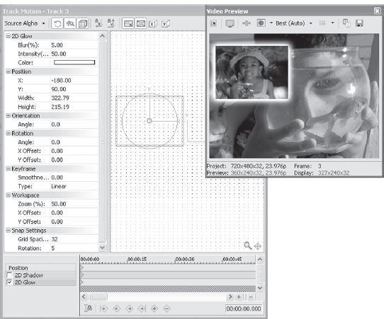
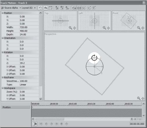
Notice that in the upper left of the dialog there is an option for Source Alpha modes. This is where you’ll access the 3D behaviors for Vegas.
Click the dropdown menu from the Source Alpha Modes button and choose 3D Source Alpha from the menu choices. A new dialog opens up within the Track Motion tool.
In the left -hand side you’ll find several controls for the 3D parameters. The primary controls are for X, Y, and Z axis. Manipulating the X axis moves the media along a right or left horizontal plane, manipulating the Y axis moves the media placement along a vertical plane, and manipulating the Z axis moves media forward or backward in a vertical plane.
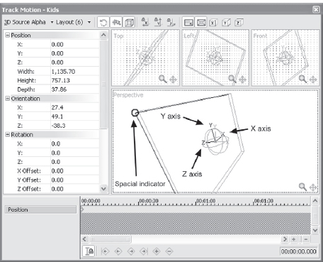
7.38 The three planes are accessible in the Track Motion workspace. Zoom in for greatest control if you are moving planes with the mouse rather than using the spinner, slider, or dialog box.
Notice that there are controls for Position, Orientation, Rotation, Keyframe, Workspace, and Snap settings. Each of these control groupings may be minimized or maximized by pressing the plus or minus sign next to the parameter control heading.
In the Position group, select the X parameter. (You may need to maximize the group by pressing the + symbol if the group is not fully visible.)
When the parameter is selected, a small dialog containing numeric value, a spinner control, and slider control open up. Position value information may be input manually by typing a value into the numeric dialog, or values may be determined by moving the spinner or slider values up or down, allowing preview of the media position.
For the purposes of this exercise, set the value to 1.0. This will move the media to the right, nearly half way.
Select the Y parameter and set the value to 00.00.
Now select the Z parameter. It will adjust in exactly the same manner as the X and Y parameters. Set the Z parameter at a value of –100. This will cause the media to zoom forward.
To adjust the 3D placement, enlarge the Orientation dialog if it’s not already open. (You may wish to minimize the Position dialog by pressing the “–” button next to the Position indicator.) Select the X plane.
Adjust the values of X to 148, the value of Y to 50, and the value of Z to 130.
This adjusts how the image floats in 3D, but these positions are also keyframeable. Place the cursor at the out point of the video on the timeline. Enable the Sync to Cursor button in the Track Motion dialog.
Notice how the cursor moved in the Track Motion keyframe timeline, to a new location that matches the location of the cursor on the workspace timeline.
Here’s where you can learn another method of manipulating how the parameters are controlled in the Track Motion dialog.
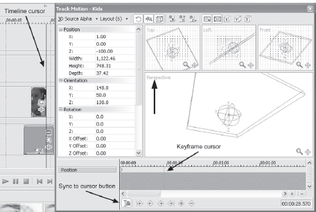
7.39 The window view may be varied by selecting the window description in the upper-left corner of the dialog. Notice the sync to cursor button in the lower-left corner of the keyframe dialog. This will sync the cursor in the Track Motion keyframe dialog to match the location of the cursor on the timeline.
In the lower portion of the Track Motion dialog, the Perspective Window is found. When the cursor is rolled over the center, or location of media, a box will highlight. This box indicates the X, Y, and Z axis of the media.
Roll the cursor over the edge of this box, and a small circle will appear in the corner of the spatial indicator box. Click and drag on this circle, enlarging the image. Notice how the numeric values in the Width, Height, and Depth dialogs change in the Positioning window)
Drag the corner of the spatial indicator box until the Z value reaches 3732 in size. If you try to input the numeric value, the aspect ratio of the media will change unless you have Lock Aspect Ratio enabled.
Beneath the Orientation group, you’ll find the Rotation group. In this group, the media may be rotated on any of its three axes. For this exercise, click on the keyframe that was newly created in the previous step, where the size of the media was dragged larger.
Now select the Z plane in the Rotation dialog, and input a value of –60 by either manually entering the value, using the spinner, or using the slider to set the value.
Like all other tools within Vegas, double-clicking the slider will reset the slider to default value. This is very useful when finding yourself a little lost in the early stages of learning the 3D tools.
Double-click the file and press the spacebar to begin playback of the file. Notice how it flies across the Preview window and rotates.
To see an example of how this functions, open the 3D#2.veg file found on the DVD in the back of the book. It may also be located on the VASST.com website.
Nesting Composites
Another great and very powerful feature found in Vegas are the nested compositing features. In earlier versions of Vegas, the compositing tools were powerful but were limited in creating in-depth composites. Vegas 5 and 6 can have multiple tracks entirely controlled by one parent track. Individual tracks may have their own motion in space using 3D or 2D tools, with a master composite track controlling all tracks beneath it that are assigned to it. This is great for building monster composites and having one final track control it. In the audio world, this is similar to a mixdown, with a master volume, pan, and effects. The tracks of video are all controlled by the master. In the case of nested tracks, even the master track may have its own 3D properties as well, that affect all tracks nested, or acting as children to the parent or master.
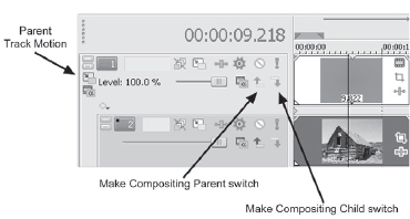
7.40 For those familiar with Vegas 4, parent/child switching is slightly different, due to the nested compositing modes.
Follow these steps to understand the basics of Parent/child tracks:
1. Create four new video tracks (Ctrl+Shift+Q)
2. In tracks 2-4, place either video or generated media.
3. On each track, open the Track Motion dialog, turn on 3D Alpha mode, and create 3D motion in each track so that all three tracks reveal themselves at some point in the project.
4. In each track header, there is a Parent/Child switch. Press the switch to cause all tracks to act as child tracks beneath the parent.
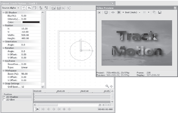
5. In track one, open the Parent Track Motion dialog, and enable the 3D Alpha mode on the parent track.
6. Create movements on that track, using X, Y, Z planes, orientation, and rotation. All three tracks beneath the parent will respond to the parent track motion regardless of their own motion.
7. In the Parent track, insert text or other form of media.
8. In the track header of the Parent track, click the Track Motion button. Enable 3D Alpha Channel mode in this dialog. Assign 3D motion in this dialog as well, creating keyframes to animate the track. This track animation is independent of the other three tracks that are children to the parent track, yet the parent track controls this track’s motion as well. Therefore in this composite, there are five track motion elements occuring at one time. Each of the four beneath the parent will respond to the parent track motion regardless of their own motion.
9. In the parent track, insert text or other form of media.
10. In the track header of the parent track, select the Track Motion button. Enable 3D Alpha Channel mode in this dialog. Assign 3D motion in this dialog as well, creating keyframes to animate the track. This track animation is independent of the other three tracks that are children to the Parent track, yet the parent track controls this track’s motion as well. Therefore in this composite, there are actually five track motion elements occuring at one time. Each of the four tracks has its own track motion element, with the parent track controlling each of these tracks in a separate motion path. You also may need to move the parent position by a few pixels in order to see the shadow or glow beneath the child tracks.
As you are working on individual tracks, notice that the track header number contains a small blinking indicator signifying which track is being affected by whatever process is being applied. This is particularly helpful when working on parent/child comps, as this makes it clear as to which track is currently selected. Even when multiple tracks are selected, only the track whose properties are going to be affected will blink.
Effects may be set up to be pre or post-process in the keyframing tool for that particular effect. Pressing the Pre/Post Toggle button in the effect will instruct Vegas when to process the media with that specific filter. Tracks in 3D mode may not be pre- or post-toggled.
Select the Pre/Post Toggle button in the keyframing tool for each effect. Vegas will automatically reroute or reorder filter position for you.
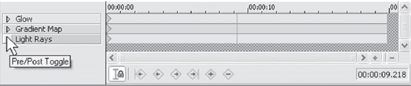
7.41 If the triangle points left, it’s pre-compositing, and if it points right, it’s post-compositing in behavior.
Parental Guidance/Shadows and Glow
Another benefit of a master parent track is that all child tracks may be assigned a master shadow or glow. This allows for a more cohesive composite as opposed to creating separate shadows and glows individually.
In the composition created earlier, open the Parent Track Motion, and disable the 3D Alpha Channel mode.
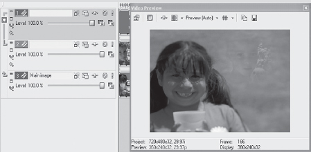
To the left of the keyframing timeline in the track motion dialog is a checkbox for Shadow and for Glow. Enable the Shadow, and you’ll see the child tracks have shadow showing where the background allows it to be seen. You may need to create a non-child track at the bottom of the timeline that contains a white generated media slug in order to see the shadow, depending on the color of your shadow and media content.
You can also insert a white slug on the parent track, and insert a compositing envelope on the parent track. This will allow the parent track to control opacity of all nested media. Open the Rings-opacity.veg file found on the disk in the back of this book. Notice how the parent tracks control opacity of tracks nested as child tracks. Move the handles on the composite envelopes on the tracks to get a feel for how this works.
To insert a composite envelope to control nested tracks:
1. Create the composite as you’d like it to appear.
2. Insert a new video track above the composition.
3. Parent the new video track to the tracks beneath.
4. In the new parent track, choose the compositing mode tool in the header, and select Multiply/Mask mode.
7. Choose the Parent Track Motion button in the parent track. In this track, you’ll assign 3D motion (or any other motion to the child tracks). Assign any motion you would like, if any. Otherwise, right-click the track header and insert a compositing envelope. Double click the compositing envelope to assign handles to the envelope, allowing the opacity or transparency of the track to be adjusted.
Growth Curves from Vegas 4 Users
The new Track Motion tool and Pan/Crop tool are definitely and deeply different from what previous versions of Vegas offered. However, these new tools, in spite of a slightly more difficult learning curve, offers a tremendous new power in Vegas. Opening composites from Vegas 4 and opening them in Vegas 6 will help learn how the new tools function. Essentially, the masking tools are the same, with the exception of the addition of 3D. There are some minor irritations for those familiar with the former track motion and Pan/Crop tools, for instance, the lack of ability to move the target inside the Track Motion dialog via up and down arrows is something I find challenging. According to the engineers at Sony, this was a challenge to keep implemented along with the addition of 3D tools. I also find the lack of a background to be difficult in these tools, as I was used to the black or gray gridded backgrounds found in earlier versions of Vegas. In spite of these differences, it’s fairly simple to learn to work with the changes and discover all the new tools which allow and encourage you to be more creative.
Vegas has the ability to create or generate media using nothing but plug-ins (no physical file is required) that can generate titles, solid colors, noise, gradients, checkerboards, and other graphic elements. You can quickly and easily generate colors for inserted media, masks, filling backgrounds under titles that don’t have associated video or graphic events, and many other uses.
To learn how to create generated media, insert a new video track on a new project by right-clicking the Track Control pane and choosing Insert New Video Track or by pressing Ctrl+Shift+Q.
Right-click in the timeline area of the new track and choose Insert Generated Media from the menu. The Generated Media dialog opens.
Select Sony Solid Color. The Solid Color dialog box opens, and you can select the color of choice. For this exercise, choose Black.
After setting the color, set the length of time that the event should last and close the dialog by clicking the × in the upper-right corner of the dialog. A black event now appears on the screen.
Click the Event FX button found on the event, or right-click and choose Event FX.
From the FX dialog, select two plug-ins: Add Noise and Black Restore. Both can be selected at the same time by pressing and holding Ctrl down while selecting the second FX plug-in. On the top/header of the plug-ins dialog, you should see both FX names displayed.
Click the Add Noise box. In the Add Noise plug-in dialog box, uncheck the Animate check box, and slide the Noise Level slider to 1.0. In the Black Restore dialog, set the threshold for 0.600.
You have just created a star field from nothing more than computer-generated media.
To add more media to the star field to make it more realistic or interesting, insert a new video track above the existing track. Right-click in the timeline area and choose Insert Generated Media just as you did before.

7.42 The Solid Color dialog box is used to define solid colors on the timeline.
Now follow these steps:
1. Choose Sony Color Gradient.
2. Select Sunburst from the menu. Notice that by moving the target marker around in the Gradient Preview screen, the curve of the gradient can be adjusted.
3. Define the length of time that the event should occur. This length of time should be the same length of time as the previous event created. Now close the dialog.
The new gradient now covers the entire Preview screen. To show only the portions that are to be actually seen, select the Video FX tab on the bottom left of the screen or click the Event FX button found on the new gradient. Choose the Cookie Cutter FX plug-in.
In the Cookie Cutter dialog, select the Arrowhead in the Shapes menu. The screen can still be covered with the Sunburst image. Using the Size slider, size the arrowhead so it is not filling the entire Preview window. A size of around 0.050 is a good choice. Close the Cookie Cutter dialog.
Now open the Track Motion dialog on the track with the arrowhead. Place the cursor on the upper-left corner handle of the frame. The cursor will change into a circular shape, indicating that the Track Motion tool is prepared to rotate the frame.
Rotate the frame so that the arrowhead in the Preview window is pointing at the lower-right corner of the Preview window.
Click and hold in the middle of the track motion frame and slide the frame to the upper-left corner of the frame window. The arrowhead in the Preview window will move to the same location and should still remain pointed at the lower-right corner.
Enable the sync cursor in the Track Motion Keyframe section. In the timeline, place the cursor on the right edge of the generated media event. In the Track Motion tool, move the fameto the lower-right corner. A new keyframe will be inserted in the timeline as a result of the sync cursor being enabled.
7.43 The cursor changed to a rotating cursor, used for rotating the frame inside the Track Motion tool.
Now press the Spacebar or click Play on the Transport control. You should see the arrowhead flying across the star field, and if the loop is enabled (press Q), the arrowhead/starship will fly across the screen from the upper left to the lower right.
Adding an orange glow and sizing it to cover only the back of the arrowhead will create a flame coming out of the back of the arrowhead/ starship. By animating the feather, opacity, and intensity of the glow, the lames can come to life, moving at different depths and opacity, giving a realistic sense of video to an otherwise static image.
![]()
This project can be found on the DVD included in this book and is labeled compositerocket.veg. The keyframes animating the flame are also found on the VEG file.
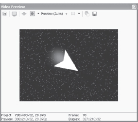
7.44 Flames created with glow give a realistic edge to the starship.
Credit Rolls
Inserting a credit roll is one of the generated media options in Vegas. Credit rolls are used for more than only titling at the end of a video project; they are great for showing specific product information, creating introductions to a video, or creating fast-moving numbers or letters for a specific effect, particularly when used at reduced opacities.
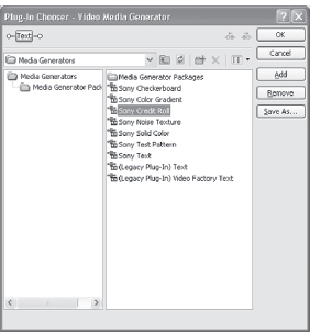
7.45 The Credit Roll plug-in is found in the Generated Media chooser.
Insert a credit roll by right-clicking a track and selecting Insert Generated Media from the submenu. In the Generated Media chooser, select Credit Roll from the listing of available generated media types.
The Credit Roll plug-in offers many choices to manage text in the credit roll. Three text settings are allowed in the roll: a Title Text (headline), Subitem Text (main topic), and Item Left/Item Right (sub-topics). Each of the three settings can have its own font size, color, style, and position.
The type of line can be adjusted by clicking next to the field in which the text will be entered. For example, a single line of text can be either a Title Text field, or it can be a Subitem Text field.
![]() Tip
Tip
You can also use the standard title tool and the Pan/Crop tool to create credit rolls. Simply type text into the Text Generator for its full length, then use the Pan/Crop tool to pan up/down the generated text, creating a very controllable credit roll. This method offers more options tha the standard credit roll function.
The type of text is selected by clicking the small box next to the input field. Clicking in the field allows text to be input to the field.
In the Style dialog, kerning, spacing, and connecting styles, such as dashes or dots, can all be specified. All aspects of the credit roll can be keyframed. Because of the nature of the credit roll and generated media, there is no sync cursor ability.
The length of the event determines the speed of the credit roll, and the number of lines determines how fast the roll moves through the length of time. Longer event lengths with fewer lines create a very slow crawl, while short event lengths with several lines scroll more quickly.
From the Properties dialog, a timed sequence can be created. In a timed sequence, titles can be zoomed in and out, faded in and out, and slid from the bottom, top, and side depending on selection in the menu. The number of lines and length of credit roll event determines the length of time of each title image on screen.
By default, credit rolls are of transparent background. Background colors, transparency, and letter colors, however, can all be adjusted. Shadows and glows are not options in the credit roll.
Using the 3D Track Motion tools, DebugMode 3D plug-in, a ump map, or height map (discussed later in this chapter) can add a number of options and creative ability to the credit roll.
![]() Tip
Tip
To add a shadow or glow to a credit roll, open track motion. Leave the track position at default but check the shadow or glow (or both) check boxes. These settings add a shadow or glow to the characters on the credit ol. Tes ca bekeyframed on or off or for position if the shadow or glow is desired to flow differently from the direction of the credit roll.
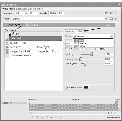
7.46 Selecting the Styles tab allows parameters of each of the three styles to be adjusted. Clicking the Style button on the left side of the Credit Roll plug-in chooses which text style the line will present.

7.47 Connect the left and right credits on the scroll with dashes, dots, or lines.
7.48 Using Track Motion in 3D mode (or using the DebugMode3D LE plug-in), text can be angled on the screen, resembling a wall or doorway. Height mapping can be used to wrap the text on a textured surface.
![]() Tip
Tip
If credit rolls have jagged edges or aliasing, try resizing the generated media to double size, or 1440×960, and reducing opacity of the credit roll to 98% rather than 100%. Don’t use fonts with serifs or fine linens. Adding .001/.002 of Gaussian Blur can sometimes help clean up soft edges on credit rolls, as can the Unsharp Mask filter.
Masks are exceptionally powerful tools for creating composited media. The generated media project created earlier contained a mask, inserted with the Cookie Cutter plug-in.
Masks can be made from just about any photo editing tool, font, or shape that exists. Vegas auto-senses an alpha channel from most images that contain them and has options to force recognition of an alpha channel if it is not automatically sensed.
To force Vegas to recognize an alpha channel if it is not seeing the channel automatically, right-click the event containing the alpha channel. Select Properties from the submenu that appears. Select the Media tab in the Properties window and at the bottom is a menu labeled Alpha Channel. Next to this, locate a drop-down list that offers several choices. Select Premultiplied from the menu.
An alpha channel defines the areas you want to be transparent. Each image on the video screen is comprised of four channels: red, green, blue, and alpha. The alpha channel acts as a mask, instructing the other channels on how the pixels should blend or merge. Alpha channels can have gradations, allowing blending of multiple images on top of each other at various levels of transparency. Another way to understand how an alpha channel functions is to imagine a stencil laid over an object and a can of spray paint. The alpha channel reveals the events beneath much as a stencil reveals the object beneath. Alpha channels usually display transparent areas as white space, while hidden areas are displayed in black.
Masks can either hide or reveal information/images in a video project, allowing image areas to be defined within an event. Another name for a mask is a matte or a key. All terms mean the same thing: hiding or revealing an area so another image can show through, or hiding an area so that another image can be composed over the top of it. In any definition, a mask, matte, or key defines the transparent pixels of an image for superimposing or revealing another image.
Just as titles are one of the simplest forms of compositing, they are also one of the most viable uses of masking. Titling is an excellent method of learning exactly how a mask works.
Open a new project in Vegas. Insert three new video tracks. Choose a video or still file to serve as a background. To create the mask, place the video or still image on track 3.
Place a title on track 1. Do not use fonts that contain serifs or small lines. A font such as Impact or Arial Black will serve best as you learn this technique.
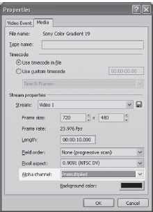
7.49 Right-clicking and selecting PROPERTIES | MEDIA allows alpha channel recognition to be forced if alpha channel is present.
On track 2, place a video file that has high motion with bright colors for the best effect in the learning stage.
The text is a mask but is not seen as such just yet. On the extreme left side of the Track Control pane, there is a small arrow pointing upward, which is the Make Compositing Child (Parent/Child) button. Clicking this button will cause all areas of tack 2 to become transparent. The only portions of track 2 that are seen are seen inside the letters of track 1. Click this button.
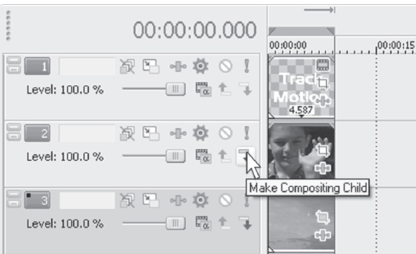
7.50 The Parent/Child button is found on the left side of every video track.
The event on track 2 disappears and becomes visible only inside the title letters. The letters are a mask; the letters become the parent, and the event beneath becomes the child. This process causes the parent to instruct the child how to be shown. Multiple tracks can be the child, but only one track can be the parent. As many parent and child relationships as necessary can exist across multiple tracks; however, but no child track can have more than one parent. If multiple parents are required of a child track, the child track must be duplicated.
To gain a better understanding of the masking process, change the color of the text on track 1 to black. It will cause the letters to become invisible. Reset the color of the title to white in order to continue this section.
This process is masking in its most basic form. Any image that contains transparent/ alpha information can be used in place of a title. To continue the concept of manipulating the title appearance, however, keep this project on the timeline.
In track 1, right-click the title to edit it or click the Edit Generated Media button found on the title event. The Title tool opens. Navigate to the Effects tab and select a shadow on the text. The shadow can’t be seen. Changing the color of the shadow will result in the shadow being seen.
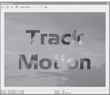
7.51 The video of track 2 (the child) shows through the letters of track 1 (parent track).
To place a shadow on the mask, or placing letters in this instance, select the Track Motion tool on track 1. In the Track Motion tool, check the Shadow check box. A shadow will appear beneath the mask/letters on the Preview screen. This shadow can be keyframed in exactly the same way that a shadow in a normal track motion instance would be keyed. Color, size, feathering, transparency, and position can all be user-defined using keyframes.
Open your favorite photo editing application. In the application, create a new project/photo image that is 655 × 480 pixels for NTSC or 704 × 576 for PAL. Flood the entire work area with black.
Paint a design or shape in the work area, using white as the color. Save the design as a PNG file for best results. A GIF, JPEG, TIF, or Targa will also work.
Open a new project in Vegas. Create three new video tracks. Place the new image on the timeline on track 1. The explorer might need to be refreshed in order to see it in its newly saved location. Refresh the explorer by clicking the Refresh button on the Explorer toolbar.
Insert the media that should be showing through the mask on track 2. The length of the event doesn’t matter, as the length of the parent event determines how long the underlying event is visible. (Of course, if the child event is shorter than the parent event, the child will not be seen for the full length either.)
On track 3, insert an event that contains video or a still image that functions as the background image.
7.52 You can have fun while learning to make masks.
7.53 Adding a shadow to the mask with the Track Motion Shadow tool. Glow can also be added to a mask.
7.54 Any shape can be used to create a mask, so long as it contains a mask and an alpha image.
In a gradient mask, white areas are revealed, while black areas are hidden. When using other colors as the mask, the closer a color is to white, the more revealed it becomes, while just te oposite is true for gradient colors approaching black in value. However, when using other colors in a mask, those colors reduce the opacity of the underlying image.
7.55 Black to white gradient changed to solid blue gradient, reducing the opacity of the image shown through. (See Figure 7.34 for the original mask appearance.
Now click the Parent/Child button on track 2, and the image you created becomes transparent, except the visible mask areas, which now show the event on track 2.
Filters can be applied to the events on the child track, which will affect how the events on track 2 are shown. Applying blurs will blend the mask into the underlying events.
Another means of creating a mask in Vegas is to use generated media to define what will be masked out. One useful way to do this process is to create a mask that splits the screen in two or three parts, using blur and mask to create a completely smooth transition from one side to the other.
To create a split screen with a seamless transition:
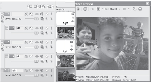
1. Insert three video tracks. Track 1 is for the mask, track 2 for one half of the screen, and track 3 for the remaining half of the screen.
2. Insert the desired events on tracks 2 and 3.
3. On track 1, insert generated media by right-clicking in the track 1 area of the timeline and selecting Insert Generated Media. In the Media Generator plug-in dialog, select Sony Solid Color and choose white as the color.
4. Select the Pan/Crop tool on the generated media by right-clicking or by clicking the Pan/Crop button found on the media. In the Pan/Crop Preview window, slide the frame to the right until it divides the frame in half. (The Center should be at 720 and 240.) Close the Pan/Crop dialog box.
5. On track 2, click the Parent/Child button on the right side of track header. This step will cause the screen to split in half, showing track 2 on the left side of the screen, as it is being masked by track 1 and the pan/cropped image. If the images on tracks two and three are not centered, the Pan/Crop tool should be applied to the images to center them.
6. With the screen split, apply a Gaussian blur to the event on track 1 either by dragging the blur to the event from the Video FX docking window or by clicking the Event FX button on the solid color event on track 1. Apply the blur to the desired setting.
7. This process can also be applied in a series of two ofttrasitonsas well, by adding two more tracks to the project. This step will display three split sections Pan/Crop will need to be applied in opposite directions and in thirds of the screen.
7.56 Splitting the screen with the Parent/Child feature.
7.57 Splitting the screen into three parts is fast and simple with maskes made from Generated Media.
The project shown in Figure 7.57 can be found on the DVD in this book. The filename is 3screen.veg.
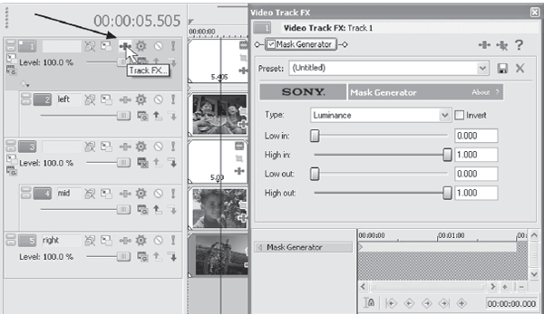
7.58 Access the Mask Generator by clicking the Mask FX button found on any Parent/Child combination.
Vegas also has a Mask Generator for every video track parented to another.
Five different mask modes are available in the Mask Generator dialog. Each mode blends or masks media differently, based on color or luminance found within the parent image, and are described here:
• Luminance—uses luminance in the image to determine transparency.
• Alpha—uses an alpha channel to determine transparency.
• Red Channel—uses the color red to determine transparency.
• Blue Channel—uses the color blue to determine transparency.
• Green Channel—uses the color green to determine transparency.
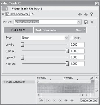
7.59 Specific color channel controls determine the transparency of that color’s channel..
Open the colorchannel.veg file on the DVD in this book.
Use the Low in/High in sliders to limit or delimit the information in the Child events in the Parent/Child relationship. These attributes are keyframable and can be used to limit/delimit transparency of a channel over time. Use this tool as one alternative to animate lines on a map, create handwriting on an image, or mask out a color channel over time.
There are many creative ways to use masks in Vegas. Using masks, a reflection of text can be quickly composited.
Open a new project. Insert six video tracks. Do the following steps in this order:
1. On track 6, insert a background image. For purposes of this exercise, use generated media, preferably a color gradient.
2. On track 5, double-click the media on track six to create a selection. On track 5, right-click to insert text media. For this exercise, keep the text to one single line. Use a creative font for best results.
3. On track 4, with the selection still active from double-clicking track 6, right-click and select INSERT GENERATED MEDIA | SONY COLOR GRADIENT. (If the selection is not active, double-click track 6 again.) In the Gradient dialog, select the Linear White to Black from the menu. In the Aspect Ratio Angle dialog box, enter a value of 37. In the keyframe timeline of the Color Gradient dialog, click the Last Keyframe Button to move the cursor in the dialog to the end of the selection/event. Rotate the Aspect Ratio Angle to –180.0, which will cause the gradient to rotate in the project. Now select the Parent/Child button on the right of track 7.
4. Right-click the text on track 5 and select Copy. Right-click in track 3 and select Paste. Vegas will ask if you wish to create a reference to existing media or if you wish to create a new copy. Select New Copy.
5. On track 5, select the Track Motion button. In the Track Motion dialog box, right-click in the Track Motion Preview window and select Flip Vertical. The “F” in the Preview window will now be upside down in the Preview window. Now resize the track preview to 947.1 × 568.3. Center the image at 360.0 × 360.0.
6. Still working on the event on track 5, insert the following event FX: Add Noise, Gaussian Blur, Deform, and Light Rays. These plug-ins create the illusion of a reflected surface. Set the Add Noise plug-in to 0.168, with Monochromatic and Gaussian Noise boxes checked. In the Gaussian Blur dialog, set the Horizontal value at 0.023 and Vertical at 0. In the Deform dialog, set the Amount to 1.00. Check the Center Image box. Leaving the Left and Right sliders set at 0, set the Top slider value to –0.209, and the Bottom slider value to 0.510. Finally, set the Light Rays to the values shown in Figure 7.58.
7. Place the cursor in the center of the Light Rays keyframe timeline. Set the Strength value to .550 and move the Light Source indicto toth center of the preview box. Move the cursor to the end of the keyframe timeline in the Light Rays keyframe timeline. Set the Strength value to .250 and move the Light Source indicator to the far right of the preview box.
8. Right-click the mask on track 4 and select Copy. Paste this copy on track 2. Once again, Vegas will ask whether a new copy should be created or a reference to the original file should be made. Create a new copy. Click the Edit Generated Media button found on the generated media on track 2. In the Aspect Ratio Angle dialog, on the first keyframe, enter a value of 0.0. Now click the last Keyframe button in the keyframe timeline and enter a value of –180.0. On track 3, click the Parent/Child button to cause track 2 to be a parent to the text event found on track 3.
9. Create a selection again by double-clicking any event on the timeline. On track 1, place a Sony color gradient. In the Gradient dialog box, set the values to the settings shown in Figure 7.61.
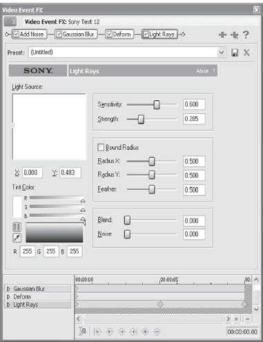
7.60 Light ray values
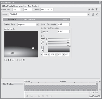
7.61 Settting values
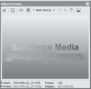
7.62 Creating a reflective surface is very fast, and requires no additional plug-ins.
Use the RAM Preview Render setting by creating a selection of all the media and pressing Shift+B. Vegas will take a moment to render the project to RAM. Be sure that RAM preview is set to the maximum available amount in the OPTIONS | PREFERENCES | VIDEO dialog. The default setting is 16MB of RAM. To render this project, you’ll need at least 300MB of RAM available.
Vegas has 14 different compositing modes. Source Alpha is the default mode, while additional modes can be used for a number of image manipulation and creative settings.
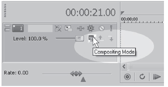
7.63 Compositing Mode button on each video track.
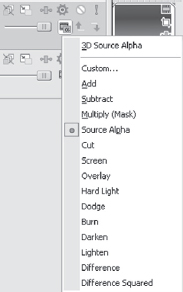
7.64 Various compositing modes in Vegas
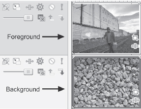
7.65 Original foreground and background events.
Compositing modes define the manner in which a higher track combines with a lower track. As higher-level tracks dominate, for purposes of reference, the higher-level tracks are referred to as foreground, and lower-level tracks are referred to as background.
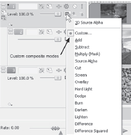
Compositing Mode tools allow for rapid access to creating multilayered images quickly. Compositing mode parameters are not adjustable. Using compositing envelopes allow you to adjust compositing level, or color management plug-ins can be used to provide opacity, chroma (color), and transparency control over all events. For instance, in the Add mode, using the Color Correction Secondary plug-in, combined with blur, creates a moving sonic wave. Using the Screen mode creates a more organic property in the sonic wave, almost as if it were a moving cloud.
Vegas 5 introduced a new compositing mode feature. When tracks become parented to one or more lower tracks, a new icon will appear in the Track Control pane of the uppermost track of the parent/child set. This is the Parent Track Overlay Mode button.
The Parent Track Overlay Mode button provides options to manage masked events above other events.
Out-of-focus video is sometimes an issue with even the most experienced of videographers. Using the Hard Light composite mode and a plug-in or two, marginally out-of-focus video can be brought to a faked focus or at the least, a more sharpened image.
Place the problem footage on a track and duplicate the track. On the upper track, apply the Convolution filter and the Sharpen preset in the Convolution filter. Reduce the opacity of the upper track to approximately 50 percent. Various settings will apply to individual events. On the lower track, apply a Hard Light compositing mode.
Some events with good color balance can also benefit by applying a Hard Light overlay mode in the compositing modes selection.
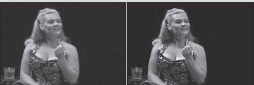
7.66 Before and after applying Hard Light and Convolution Kernel filter.
7.67 Parent Track Overlay Mode button.
7.68 Parent Track Overlay mode.
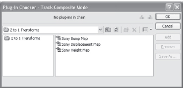
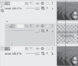
When you select this button, there are two menu choices. The first is the default Multiply mode, and the second is Custom. Selecting Custom opens a dialog offering three compositing overlay modes: Displacement Map, Bump Map, and Height Map.
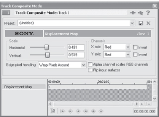
Displacement Map
This mode uses the parent image as a controller to offset the pixels in the composited child tracks along the X and Y axes, his process uses a two-channel displacement. In other words, pixels are displaced to the left, right, up, or down depending on their relationship to colors in the mask. The displacement map is also useful for following contours of shapes.
7.69
This plug-in can be challenging to control. Working with solid colors or gradients as masks will yield the best results, particularly when learning how to use this tool.
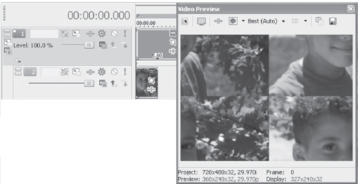
7.70 Using a red mask causes the image to shift in a clean four-way split.
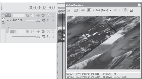
7.71 Using a blue-to-green mask causes the image to shift all pixels to the right, creating an extremely wide-angle appearance around the center of the screen without the associated rounding of the image, or vignetting.
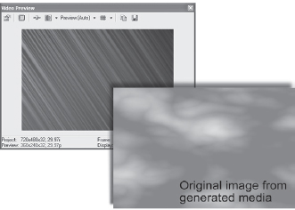
7.72 Ordinary clouds shift to streaks of movement using the height map to shift pixels farther from their original position.
7.73 Three tracks are required to create the project illustrated in Figure 7.72.
![]()
To learn more about the displacement map, create two video tracks and place the stone.png image on track 2. Create a title using a bold font on track 1. Duplicate track 2 and slide the new track so that it is track 1, the text is on track 2, and the original image is on track 3.
Now make track 1 parent to track 2, which will cause the text to be masked.
Check the Composite Mode button and choose the CUSTOM | SONY DISPLACEMENT MAP from the menu that opens.
In the dialog box, change both channels to Red. In the Horizontal axis, set the value to-0.018 and the Vertical axis to 0.027. The appearance of the text in the Preview window will vary depending on the font used. Experiment with the slider values to find the appropriate setting. Notice how the lettering conforms to the rocks in the photo. Using a text color slightly lighter in hue over the rocks completes the effect.
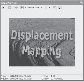
7.74 Three tracks were used to create this effect.
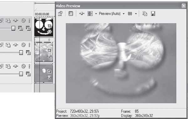
This mode uses the parent image as a controller to cause pixels in the composited child tracks to appear closer to or farther away from the viewer. Adding a height map is a great tool for creating the appearance of moving water or viewing an image through glass or water, creating shimmers, fire, or smoke over another image. This mode can be added to gradients, masks, or other images above lower images.
To learn more about the height map, create a new project. Insert two video tracks.
Place the image rings.png from the DVD in this book onto track 1 and place a video or generated media event on track 2. Now make track 1 parent to track 2 by selecting the Parent/Child button on the left side of the Track Control pane.
On track 1, click the Compositing Mode button on track 1. From the menu, select CUSTOM | SONY HEIGHT MAP.
Enter the following settings in the dialog box:
• Amplitude—0.023
• Elevation—0.319
• Height Scale—0.320
• Smoothness—11
• Source Channel—Intensity (menu selection)
• Edge Pixel Handling—Wrap pixels around (menu selection)
Add a pan/crop to the event on track 1, zooming in by 40 percent. Experiment with the Amplitude and Elevation settings in the Height Displacement dialog box in order to better understand how this plug-in functions.
Any track-level keyframes can be viewed, moved, and edited directly from the timeline. By expanding the keyframes in the track view, keyframes can be slid forward or backward in time and double-clicked to open the track motion or compositing keyframes Tis feature provides a visual reference at all times when there is track motion or compositing information on a track, which allows for cursor placement on musical beats, specific musical or dialog points, or simply provides a reference to what is being seen in the Preview screen.
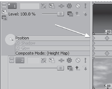
7.75 The Expand Track Keyframes button opens a keyframe pane directly on the timeline.
In nearly all of the previous projects, a gradient mask is used. Gradients and other generated media forms are very useful as masks. As an example, try this method of creating a mask:
1. Insert a gradient mask.
2. For mask shape, select rectangular.
3. In the Gradient Preview window, slide the color placement control points so that they are lying over top of each other with very little overlap.
This process takes some attention, because if the control points are not placed correctly, the mask will reverse itself and change from an outer mask to an inner mask. This element can also be used as a valuable tool. A color with reduced opacity can also be added to the mask’s outer area, acting as an overlay, if desired. This type of mask is similar to the way the Cookie Cutter filter functions; however this method has greater flexibility in some instances.
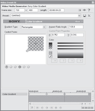
7.76 Masks can be any shape at all.
Practice using the black-to-white gradient as a mask in projects, as it is one of the most powerful masking tools Vegas offers.
![]()
Open the file called jellyfishswim.veg from the DVD in this book. It is a fairly complex project and contains many attributes found in Vegas.
Let’s look at each track individually.
• Track 1—contains generated media and height map and is at 20 percent. The generated media acts as a guide to shift pixels generated on track 2.
• Track 2—contains generated media from the new Noise Texture generator. The Noise Generator is shifting in bias, causing it to create ripples on the “water.”
• Track 3—is a gradient mask over track 4. It’s composited in an Add mode, which brightens the image and adds contrast to allow the jellyfish to stand out over the other elements.
• Track 4—is another Noise Generated event, with color shift and pan/crop to create motion in the water.
• Track 5—is a simple blue generated media overlay at 50 percent opacity.
• Track 6—is another gradient, in Subtract compositing mode, acting as a mask for track 7. This feature helps bring out the colors in the jellyfish by masking brighter color values. With some work, a similar effect can be had with a secondary color corrector.
• Track 7—is a Noise Generated event, shifting across the Frequency, Noise, Offset, and Amplitude settings. Masked by the gradient on track 6, this color sets the shimmer over the jellyfish.
• Track 8—is the still image of the jellyfish, using pan/crop to move the fish, while two instances of the Spherize plug-in create the motion in the jellyfish. There is also a minor adjustment to the color of the still, reducing the exposure of the flash in the original shot. It also contains a height map to give the jellyfish texture and shine and is mapped to the event on track 9.
• Track 9—is a Noise Generated event, creating a texture of movement under the water, beneath the jellyfish.
Underneath all these layers is a motion blur added only to the jellyfish and Noise Generated layer found on track 9. Motion blur is applied at a value of 15 percent.
With this project open, change the compositing modes, opacities, and generated media gradients or colors. See how these changes affect the jellyfish appearance. This demonstration provides a visual overview of the function of each aspect of the tools.
Bump Map
This mode uses the texture of the parent image to create a map of light and dark information. This tool is very handy for creating 3D titles, creating textures over an event, and mapping a texture to an underlying event.
Lighting angles are definable with the Lighting Type menu. Use the Intensity slider toinceas ordeceae the presence of a light. The X, Y, and Z parameters can be controlled by inputting values to the input field or by moving the target dot in the Bump Placement window. Reset the X-Y parameter by double-clicking the yellow dot or by right-clicking in the Bump Placement window and selecting Reset.
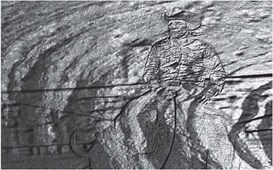
7.77 In this image, the stone creates a texture, mapped to the outlines of the cowboy, creating a handdrawn effect.
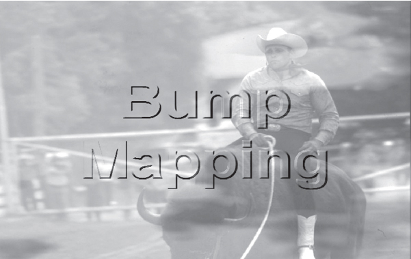
7.78 In this image, a simple text event takes on 3D attributes with definable lighting, depth, and bump height.
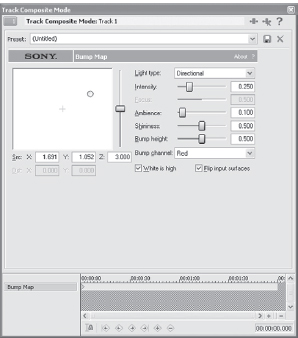
7.79 Controls found in the Bump Map dialog box control light, focus, depth of mapping, and light displacement.
The Z slider (vertical) controls the height of the light on the mapped image. When Spotlight is selected from the menu, the distances of X and Y are controllable, and the focus slider is enabled as well. Focus controls the tightness or breadth of the light image. Omni-directional and Directional menu options automatically disable the focus and X-Y distance controls. The Destination of X-Y can be adjusted by moving the X in the Bump Placement window.
The Shininess slider controls the reflective surface of the map, and the Ambience slider controls the amount of light seen in the mapped image.
The White is high check box causes the bump map to view white areas as the highest areas of the bump texture. Leaving this box unchecked causes the black areas to define the high areas of the texture.
Finally, flipping the input surface reverses the two images, causing the upper and lower tracks to flip images.
Open the bumpmap.veg file found on the DVD in this book for examples of the bump mapping shown in the images earlier.
Learning to work with these tools helps build titles, scene atmospheres, and magical shots quickly and powerfully. Compositing itself is an art form and requires a great deal of time and experimenting. Vegas has some of the most powerful compositing tools in its class of editing systems and, over all, has more compositing tools than any NLE system that doubles as a finishing editor. On the DVD in this book, several compositing projects are available, although not described in this chapter.
Using Chromakey Tools in Vegas
Chromakey, also referred to as greenscreening or bluescreening, is an art form that must first be practiced at the camera and shooting stage of a production. Even fairly weak footage, however, can be usable in Vegas when filtered with the color correction tools and chromakey tools.
Chroma (color) and key (mask) come together to create a mask from selected color(s). A quality mask or key can also be made from nearly any color or reasonable gradient of color. Selectable colors/chroma can be keyed or masked out, so that other events can show through those sections. Although industry tradition uses a screen of blue or green, any color can be keyed. Due to the luminance and chroma sensitivity of the bright green used in screens, however, in most situations, green is the best choice for DV.
(For more information on the relationship between chromakey and DV, visit http://www.sundancemediagroup.com/help/kb/ and read the tutorial on 4:1:1 DV.)
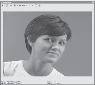
7.80 A clean greenscreen shot, with no spill on the face of subject.
Shooting a clean screen is critical to having a relatively smooth experience with keying. Many tutorials are available on how to shoot a clean screen, and the Sundance Media Group V.A.S.S.T. training course teaches this as well (www.vasst.com). Some basics to know are presented here to assist the inexperienced cameraperson/editor in creating a clean shot to be keyed in the editing stage.
Use Rosco green paint or a commercially produced greenscreen. We recommend the Photoflex dual-color screens that have flex hoops in them for easy storage. When shooting on DV, green is the only safe choice. Blue can be used in analog shooting.
Good lighting is critical. To shoot a clean screen requires at least three lights: a key light for the talent and two lights for the screen itself. A reflector for the key light to light the opposite side of the subject is valuable too, as are flags (masks) to keep the key light from spilling onto the screen.
Shoot the subject at a minimum of six feet from the screen. This practice is necessary to prevent green reflection from spilling onto the subject. This kind of reflective spill is very difficult to remove in editing, regardless of the application used for creating a key or matte.
Vegas has excellent chromakey tools that allow for rapid and clean keying of colors. A successful key, however, is also dependent on practice and experience on the part of the user.
![]()
From the DVD, open the greenscreen.avi file on the timeline in Vegas. Select the Event FX on the file and open the Sony Chromakeyer tool.
In the Chromakey dialog box, uncheck thechck oxin the upper-left corner. The Chromakey dialog defaults to blue, and unchecking this box allows Vegas to sample an accurate replacement color. Select the Eyedropper tool, found in the left center of the Chromakey dialog. With the Eyedropper enabled, click the color to be removed from the event in the Preview window.
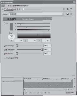
7.81 Chromakey tool at default setting. Uncheck the Chromakeyer box in the upper-left corner.
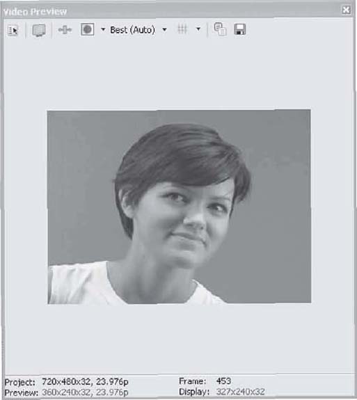
7.82 Draw or click in the Preview window to select color for removal.
Enable the Chromakey tool by placing a checkmark in the check box in the upper-left of the Chromakey dialog. A portion of the selected color will immediately change in the Preview window. Now the Chromakey tool must be adjusted to create a clean key.
Start by placing the event to be seen beneath the keyed event. This process helps adjust the key for best matting. Generated media is great for this, esecially generated media that is a similar color to the replacement event. Of course, the replacement event can also be used. If it’s a fairly busy event with lots of detail, however, it is sometimes difficult to create clean lines, as the detail in the background event hides lines during the key process.
![]() Tip
Tip
Viewing the key process on an external monitor is helpful to ensure a clean key process. During the color selection, however, the preview must be on the computer screen. After key color is selected, video can be sent to an external NTSC or PAL monitor.
After an event is placed beneath the event being keyed, slide the Low Threshold slider to the right and slide the High Threshold slider to the left. On the greenscreen.avi file, a clean key will be achieved with the Low Threshold slider at 0.400 and the High Threshold at 0.800. The Blur setting is dependent on the background media used. In the instance of the greenscreen. veg file found on the DVD, the Blur setting is at 0.015 to soften the harsh transition between the background color and the edges of the key. Some keyed events require a fair amount of blur while others can require no blur whatsoever.
Creating a Garbage Matte in Vegas
A garbage matte or mask is a simple mask, created from an event or image in Vegas, which removes one element from other elements on the screen. This option assists in the keying process, particularly where more than one color must be keyed out. The earlier project does not require a garbage matte; however, many instances exist in which a garbage matte is beneficial.
To create a garbage matte, click the Show Mask Only box in the Chromakey tool. This step displays the areas being masked and quickly shows a clean or unclean key. This matte/mask can be rendered to a new track, which is then parented to the original event, saving processor time and allowing multiple masks to take place on the timeline/project. To render the matte to a new track, solo the track containing the mask. Double-click the event to be rendered to a new track, creating a selection. Select TOOLS | RENDER TO NEW TRACK. In the dialog box, select Custom and select the Audio tab.
A popular effect is to create an image that is entirely black and white, except one or two colors. This is part of a color pass, which allows a color to pass through an image that is otherwise black and white.
To create this effect quickly, place the events on the timeline to be color passed. Duplicate the track so that two identical tracks exist. On the upper track, insert a Chromakey and Black and White filter in order.
Using the eyedropper in the Chromakey tool, select the color to be passed, or allowed to be shown. Use the View Mask Only check box to see what areas will be knocked out in black and white. Adjust the Black and White filter to the desired level of black and white blend. For maximum effect, the lower track can have a slight blend of black and white with the color. This option reduces the amount of contrast between the color and black and white areas if this is the desired effect.
Although this is one method of color-passing in Vegas, see the section on Color Correction in chapter seven which discusses alternative methods.
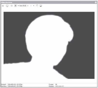
7.82 A clean and simple garbage matte/mask.
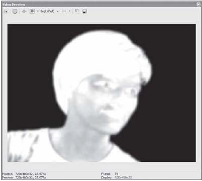
7.84 An improper mask/matte.
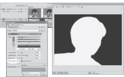
7.85 Track 1 soloed and with Show Mask Only enabled in the Chromakey tool. This process is done to render a matte/mask to a new track.
After the new track is rendered, it should be parented to the original track. Click the Event FX button on the original track and disable the Chromakey tool by un-checking the check box in the upper left of the Chromakey tool. Parent the mask event to the original event by clicking the Parent/Child button to the left of the original track.
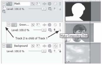
7.86 Parent track 1 to track 2 by using the Parent/Child button on track 2.
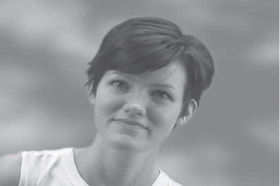
7.87 A clean composite
The two events over the third track, which contains the background information, create a clean composite over the background image if all parameters are adjusted correctly, as illustrated in Figure 7.87.
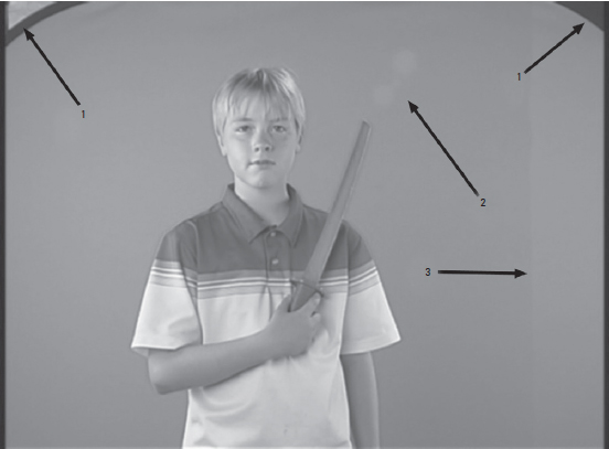
7.88 Identifying problem areas in a screen isn’t always easy or obvious.
The original image can be color corrected, blurred, or otherwise filtered for creative presentation if desired.
Figure 7.88 shows three problem areas in the screen.
1. The corners of the screen are visible. These areas will not mask cleanly.
2. Lens flare/reflection shows across screen. This will not mask cleanly.
3. There is spill getting past a flag, allowing backlight spill on the screen and creating two colors of green. This will not mask cleanly.
These problems can be overcome, but the time involved, coupled with the loss of resolution, quickly demonstrate the necessity and time savings of having media shot correctly in the production stage.
![]()
To see how to correct the poorly shot footage, open the badscreen.veg file on the DVD in this book.
A clean mask has been rendered to track 1. This garbage matte is required to create a clean composite. Track 2 is parented to the mask/garbage matte, which is similar to the way the first greenscreen project was done. To be able to create a clean mask, however, a secondary color corrector and black restore were used to cause the mask to render cleanly. The event is also panned/cropped to remove the corners from the scene and to create a clean masking area. Still the original event requires color correction to blend into the background with a believable presentation. The original settings for the color correction and chromakey have been left in place on the original event in region one. Click the Event FX to enable these two FX, allowing you to see how the mask was created. Color correction has been added to the event as well. Disable this by unchecking the check box in the upper-left corner of the FX dialog. A very small amount of blur has been added to the mask to smooth over the transition from the masked area to the background area.
These are two examples of how a chromakey can be used to repair a background image or to insert new media. There are other instances where a screen is valuable however.
Open the tvscreen.veg file on the DVD in this book.
![]()
The tvscreen.veg file contains a still image: tvshot.png. This image is an old photograph of a child watching television. The television screen has been replaced with green, allowing for a motion picture to be placed in the television screen. This method can also be used to replace screens in television studio-type shots or military establishment-type shots to create a sense of realism. There are more examples of this sort of masking on the tvscreen.veg file. Play with them and notice how the Track Motion tool is used to fill in the masked sections.
Never be afraid to experiment using various FX, track Motion, Pan/Crop, and other tools on composited media. Turn lots of knobs, slide the sliders, and check the check boxes. Various combinations turn up lots of artistic possibilities, and, as mentioned at the front of this chapter, compositing is an art form. Be creative!
Create a Holograph in Vegas!
Remember the beamed holographs seen in Star Wars episodes? At the time the movie came out, this was an exceptionally cool thing, never seen nor conceived before. Star Trek had a simple transporter beam effect that used masks to create the look of being transported, but the holograph was a method of communication and projection never before seen. Playing around in Vegas on a VASST tour, I was working with a piece of footage and realized how simple this would be in Vegas. To accomplish this look you’ll need to shoot against a solid backdrop, preferably green if you are shooting with DV. (See my tutorial on why green is better.) Shoot your footage with your actor dressed in imaginative clothing, but color of the clothing won’t matter much, as we’ll be applying a blue filter over the original footage to mask most color detail. Just be sure the clothing doesn’t contain colors that are the same or fairly similar to the background color. You’ll have the most effective look if your actor is shot full-body, but even half or three-quarters works acceptably well. However, to mimic the Star Wars look, you’ll want to do a full body shot. Remember, if this is to look like a communication transmission, your actor should look at the camera just as though he can see a video or holographic representation of who they are speaking to.
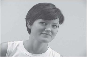
7.89 The original image is shot against a green background.
First, I used the secondary color corrector to pop my blues, allowing for better extraction from the background which has a few gradients, as we didn’t use the eye’s full lighting system. I then added a chromakey tool, and using the Show Mask Only check box, I cleaned up my output. The project .veg file has left these two tools in place, merely turned off, so you can work with the demo media to see how I popped the blue and cleaned up the output. I then used the Pan/Crop tool to create a 16:9 letterbox, and used the Track Motion tool to stretch the body and create a thinner and off-aspect appearance to the shot. After getting the mask set up, I found a background .jpeg that I wanted to insert the original image into. In this case, it’s a shot of a living room.
Next, I rendered a new track with the Show Mask Only box still checked. I unchecked Include Audio from the Render>Custom options, as I wanted the new mask track to lie directly above the original track with no audio, and the audio from the original track was used in the project, removing the need to have a second, duplicate audio track. This allowed me to create a garbage mask or matte to be used as a parent to the original image. Don’t create the mask or matte til the Pan/Crop and Track Motion attributes have been determined. Be sure ripple is disabled before rendering to new track. On the original track, remove the Secondary Color Corrector and Chromakey from the original. With the matte above the original track, Parent the matte to the original by pressing the Parent/Child button on the original track. This will allow the original track to show through. At this point, you should see a fairly clean image over top of the selected background. Set the opacity of your matte to 75 percent for starters. This will allow the background to be seen through the hologram.
Using selected filters, we’ll now create the image of the hologram. Drag the Gaussian Blur filter to the matte. Set the values for both horizontal and vertical blur to approximately .025 for starters. This will likely be tweaked later. (The project veg is set to .027.) The blur helps create a soft edge on the original media. It also washes out the screened edges and blends the image into the background a little more smoothly.
Drop the Secondary Color Corrector onto the original video track. Choose the Desaturate All but Red preset for starters. Slide the Saturation slider to the right, to a value of 3.000. Now slide the Limit Hue value to the full right, to a value of 360. Slide the corrector target dot to the lower left in the color wheel, setting the track to a blue color. Set this to the desired level. This should blow out the edges of the original media. This step is not necessary for creating this particular look. I simply wanted to blow out my edges.
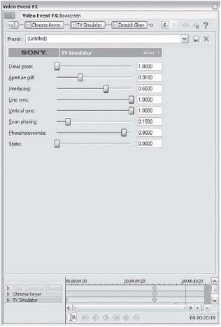
7.90 Match the sliders in this screen shot to create fast pulsing sync lines.
Now drop the TV Simulator on the original media. Select the TV Look preset. Slide Line Sync, Scan Phasing, Phosphorescence all to the right to create a fast scan image. Add a tiny value of Static if you’d like to distort the image a little further. If you want less interlacing (the horizontal lines in the image) reduce the Interlacing value to zero. For a really unique look, keyframe Line Sync and Scan Phasing value movements to make the picture break up every now and then. Notice there are no keyframes in the project. I left these blank so you could experiment with these values on your own.
Now drop the Brightness and Contrast filter on the original image, setting the Brightness value to .22. That’s all there is to it. The project ready to be rendered.
Some options you might want to try, depending on source footage if other than the media used in the training file:
• Drop the Glow filter on the footage. (The Zenoté plugin was used for the original render seen in the demo footage. It’s an excellent tool for smoothing out the highlights.)
• Drop a Film Grain filter on the original along with the TV simulator to create noise in the file.
• Use the Convolution filter to create unique effects. This won’t work for all looks but is a great look for some effects.
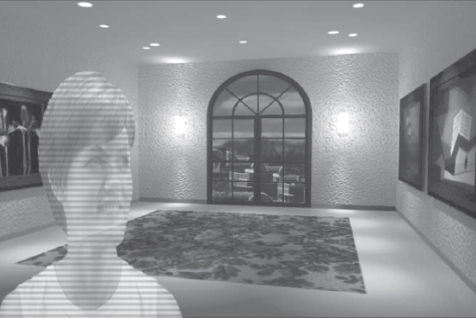
7.91 Here is the look of the final product.
Motion Blur
Vegas has a feature called Motion Blur that allows an envelope to be applied controlling the duration and shape of the blur applied to the motion of video. What makes motion blur unique is that it applies blur at the frame level, creating a blur over time (temporal) as the video shows movement. This option makes zooms, pans, and motion in the image blur smoothly. A standard blur applies a blur in 2D space or a spatial blur. A motion blur acts more like a wide-open shutter, allowing for a greater exposure time.
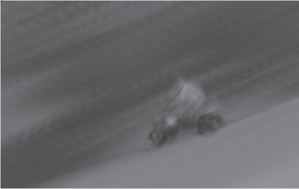
7.92 Motion blurred at full value with the Motion Blur tool
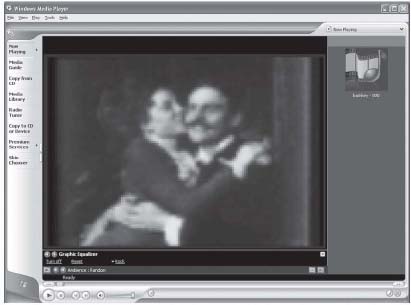
7.93 The original image from Thomas Edison’s 1900 firn. The Kiss. Notice black edges to be cropped out, bringing the image to correct aspect ratio.
Applying the envelope is performed by selecting VIEW | VIDEO BUS TRACKS (Shift+Ctrl+B) and then right-clicking the video control pane and inserting a Motion Blur envelope. Double-clicking the envelope and adding handles/nodes controls the amount of blur.
Applying this filter to sequences of still images, fast or slow motion video, and animations can add a sense of realism to the media. It can also be inserted with great intensity to generate a dream-like quality.
One really great effect to try with motion blur is to render an event with lots of motion to a new track and to add a motion blur to suit the eye. In that new track/event, right-click and select Undersample. Undersample the event by at least .750, which will create a unique and stuttered look with blur shifting. The most unusual effect comes from using extremely low undersampling/ frame rate in which the frames skip enough to cut the blurred frames to the point that they are almost unrelated in motion.
Another terrific use of this tool is to blur a camera pan when transitioning from one scene to another. A motion blur, coupled with a velocity filter and transition, is a good combination for the popular effect of stuttered motion or stopped-motion blurring during a pan into another scene or shot sequence. Motion blur does add considerable time to a rendered section, so make sure the envelope is completely off when not being used.
Every track will be blurred when this envelope is up, unless the Bypass Motion Blur button is chosen. This option allows you to selectively blur tracks. The button is next to the Scribble Strip on each video track in the Track Control pane. Leaving it enabled causes the video track to be blurred.
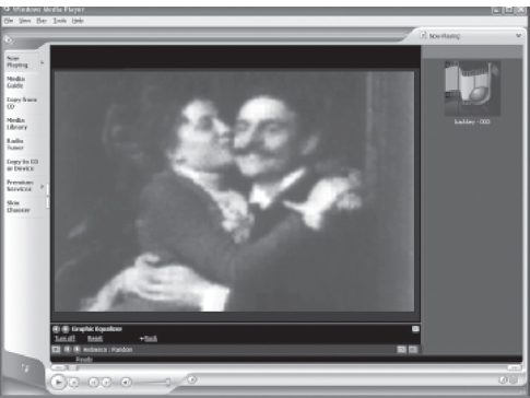
7.94 The same image after cropping and supersampling at a value of 2 frames.
Super Sampling
Super sampling resamples each pixel of video information in Vegas 6 and significantly improves the smoothness of the pixel edges and matches to adjoining pixels. This feature is primarily valuable when used in conjunction with the Motion Blur envelope but is also beneficial when used in upsampling smaller resolutions to DV or higher levels. Super sampling will not be as noticeable with video containing high motion or with video that is not being changed in output size or resolution. Use super sampling in connection with Motion Blur, upsampling small resolution video, or when working with extremely low resolution stills. It works exceptionally well when shifting the aspect ratio from one size to another, such as converting video that is 160 × 160 to 720 × 480.
The way this works is that Vegas creates interpretive frames based on the difference between the project frame rate and the frame rate of the media, or the computer-generated imagery. This process also creates smoother flow and edges for generated behaviors, such as Pan/Crop, Track Motion, Transitions, and other new media created in the timeline during the editing stages.
Insert a Super Sampling envelope in the same manner as inserting a Motion Blur envelope by selecting VIEW | VIDEO BUS TRACKS (Shift+Ctrl+B) and inserting a Super Sampling envelope. Use the envelope to control how many interpolative frames are created. For instance, by using an envelope setting of four, four times as many frames are rendered as existedin he rignal event. This means that render times are significantly slowed, so don’t plan on doing a super sample while you are answering a phone call or grabbing a quick bite to eat. Super sampling, however, is a fantastic tool when shifting resolution, frame rate, or both. It often is beneficial to add a small amount of Gaussian blur as well, to spatially shift the image. Supersampling won’t benefit media that isn’t changing aspect ratio or framerate, if it merely is being employed to go from one format to another format of matching dimension.