CHAPTER 2
The Basics of Professional Networked Media
CONTENTS
2.1.4 The Firewall and Intrusion Prevention System
2.1.5 File and Application Servers
2.1.7 Networking Infrastructure
2.1.8 Systems Management and Device Control
2.1.9 Software for All Seasons
2.2.1 General Scope of Technology Committees
2.2.2 The Eight SMPTE Technology Committees
2.3.5 The Classes in Perspective
2.4 File Transfer, Streaming, and Direct-to-Storage Concepts
2.4.3 Direct-to-Storage Concepts
2.6.1 Domains 1 and 2: Streaming and File Transfer Interfaces
2.6.2 Domain 3: Control Interface
2.6.3 Domain 4: Management Interface
2.6.5 Domains 6 and 7: Wrappers and Essence Formats
2.7 Tricks for Making IT Elements Work in Real Time
2.8 Using IT Methods to Route Traditional A/V Signals
2.9 It’s a Wrap: A Few Final Words
2.0 INTRODUCTION
This chapter reviews the essential elements of networked media as they relate to the professional production of A/V-based materials. Of course, it is not possible to present a detailed explanation of each building block, so let us call the coverage an “evaluation strength” treatment. What is this? If you need to evaluate various HW/SW architectures, system components, or systems issues, the coverage in this chapter (and others) provides you with the tutoring to ask the right questions. Rudyard Kipling said (paraphrased), “I keep six honest friends—what, why, when, how, where and who.” In the end, you will be able to ask probing and intelligent questions when evaluating and specifying AV/IT systems.
This section does a broad-brush coverage, while the remainder of the book dissects the same subjects to uncover their subtleties and deeper points. The following chapters probe deeper into select subjects:
• Chapters 3A and 3B—Storage systems
• Chapter 4—Software technology for A/V systems
• Chapter 5—Reliability and scalability methods
• Chapter 6—Networking basics for A/V
• Chapter 7—Media systems integration
• Chapter 8—Security for networked A/V systems
• —Systems management and monitoring
• Chapter 10—The transition to IT: Issues and case studies
• Chapter 11—A review of A/V basics
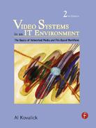
At the highest level is generic IT architecture. Figure 2.1 shows this six-tier architecture. It is deliberately abstract, as it can represent almost any process-oriented workflow. Networked media, as defined for our purposes, is more than pure networking. It encompasses all the stages in Figure 2.1. The diagram is split into two domains; the application-specific one and the shared IT infrastructure. The application layers define the various applications needed to support a workflow. The lower layers provide the services and resources that the application logic calls upon. Next, let us peel back the onion on the bottom three layers in Figure 2.1. The higher layers are considered in other chapters.
FIGURE 2.1 Generic six-layer IT architecture.
2.1 CORE ELEMENTS
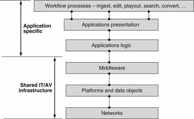
Figure 2.2 provides a 5-mile high view of a generic IT architecture for the enterprise. This is the physical representation of the logical view of the three lower layers in Figure 2.1, along with the application clients. Also, most of the infrastructure in Figure 2.2 would be found in a typical hybrid AV/IT architecture. Missing from Figure 2.2 are miscellaneous A/V links, video/audio routers, cameras, VTRs, logo inserters, video servers, and so on. IT architectures that are fine-tuned for A/V are discussed in other chapters. Nonetheless, Figure 2.2 forms the foundational elements for our discussions throughout the book. The main elements to be discussed here are
• Application clients
• The router
• Ethernet switching
• The firewall and intrusion prevention system
• File and application servers
• Storage subsystems
• Network infrastructure (LANs, WANs)
• Systems management and device control
• Software for all seasons
FIGURE 2.2 Simplified enterprise network architecture.
2.1.1 The Application Client
Clients come in all shapes and flavors. The application clients perform A/V I/O, video editing and compositing, browsing, other media-related functions, or standard enterprise applications. This book uses the term application client in a general way, implying some device that accesses storage or servers or other systemwide resources. If the client does A/V processing, then it may or may not have A/V I/O ports. For example, a nonlinear editor (NLE) may have A/V file access from a storage element in the network but it may not have physical A/V I/O ports. Another client may support only A/V I/O and not any human interface. This type of element is common for capturing content from live satellite feeds or as an A/V playout device. The network attach may be an Ethernet port at 100 Mbps, Gigabit Ethernet (Gig-E), or Fibre Channel. Why choose one over the other? These and other client-related aspects are discussed later in this chapter. See, too, Section 2.2, “A/V Media Clients,” later in this chapter.
2.1.2 The Router
The router connects the facility to the outside world or to other company sites using IP routing. A router has three fundamental jobs. The first is to compute the best path that a packet should take through the network to its destination. This computation accounts for various policies and network constraints. The second job of the router is to forward packets received on an input interface to the appropriate output interface for transmission across the network. Routers offer a selection of WAN interfaces1 (SONET, T1/E1, T3/E3, ATM, Frame Relay, ISDN, and more) and LAN (Ethernet with IP for our discussions) interfaces. The third major router function is to temporarily store packets in large buffer memories to absorb the bursts and temporary congestion that frequently occur and to queue the packets using a priority-weighted scheme for transmission. Some routers also support a virtual private network (VPN) function for the secure tunneling of packets over the public Internet.
2.1.3 The Ethernet Switch
Most campus networks are composed of a cascade of Ethernet switches. The switching may occur at the Ethernet level (layer 2) or the IP level (layer 3), although the distinction is not enforced here. Think of the switch as a subset of a full-fledged router; it is simpler and less costly than routers, although there are numerous technical differences too. Layer 2 and 3 switching and routing methods are covered in more detail in Chapter 6. Switches are the tissue of an enterprise network. Most switches can support “wire speed” packet forwarding at the Ethernet line rate (100 Mbps or 1 Gbps commonly). Small Ethernet switches (24 ports) are inexpensive with a per port cost of only $15.
Packet switches (and routers) have throughput latency that is ideally in the 1- to 20-μ s range but can grow much bigger in the presence of packet congestion. IP switches may be classed as asynchronous devices, whereas SDI A/V routers are isochronous (equal timed) in nature with perfectly timed (fixed latency, very small jitter, and bit accurate timing) I/O ports. So it is apparent that routing A/V packets is not exactly equivalent to SDI routing. It is precisely this issue that convinces some that IP switches cannot be used to route live A/V signals. After all, if live video needs to be perfectly timed to within a nanosecond or so, then the IP switch is not fit for the job. This issue is addressed later in the chapter with the conclusion that switches (and routers) can indeed be used to switch live A/V packets.
The switch internal data routing structure is either shared memory or switch fabric and can reach speeds of 400 Gbps non-blocking throughput for a carrier-class large size switch (200 ports). Terabit per second fabrics exist and are used in very high-end switches and routers. See www.avici.com and www.juniper.com for added insights. Like routers, they can support small I/O latencies in the 1- to 20-μ s range, which is ideal for moving live A/V streams.
A switch is deceptively simple from the connectivity point of view; it is just Ethernet I/O. Looking deeper, we see that it must support 20 or more networking standards for efficient packet forwarding, Ethernet frame forwarding, secure device management, flow control, VLAN support, class of service, packet inspection, multicast, and a multitude of other protocols. Routers are more sophisticated and may support 35 different protocols. There are many vendors to choose from, and the price/performance ratio is improving with each generation thanks again to Moore’s law.
2.1.4 The Firewall and Intrusion Prevention System
A computer firewall protects private networks and their internal nodes from malicious external intrusion, resulting in a compromise of system or data integrity or a denial of service. It is usually a secure HW/SW device that acts to filter every packet that transits between a secure and unsecured network. It must have at least two network interfaces: one for the network it is intended to protect and one for the risky network—such as the Internet. The earliest computer firewalls were simple routers. The term firewall comes from the fact that when a network is segmented into different parts, damage that could spread from one subnet to another is stopped—just as fire doors or firewalls stop a fire.
An Internet firewall examines all traffic routed between a private network and the Internet. Every packet must meet a preselected set of criteria; otherwise, it is dropped. A network firewall filters both inbound and outbound traffic. Disallowing internal access to select external locations is vital in guaranteeing secure and legitimate business operations. It can log all attempts to enter the private network and trigger alarms when hostile or unauthorized entry is attempted. Firewalls can filter packets based on their source, destination addresses, or port numbers. This is known as address filtering. Firewalls can also filter based on application layer protocols such as HTTP, FTP, or Telnet.
The Intrusion Prevention System (IPS) is a sort of super firewall. It filters at the content layer. For example, it may look for and prevent attacks from incoming worms, ill-formed protocols, and other higher layer tricks. A more detailed coverage is outlined in Chapter 8.
2.1.5 File and Application Servers
Servers come in many forms and are a common element in an IT infrastructure. Their basic function is to host software applications that clients can access over the network. These functions may be done in an A/V real-time sense or in nonreal time. The common functions are shown in Figure 2.2. For the purposes of A/V functions, the following are of interest:
• File server—This type of server stores/retrieves A/V files for access by clients. Normally, the delivery of files over the network would be in non-realtime. The server usually appears as a networked drive (//K: or //MyServer:) to the client. Files can be moved to and from application clients.
• A/V processor—This networked resource is used for processing A/V essence. Typical functions are compressing/decompressing, file format conversion (DV to MPEG), 3D effects, proxy file video generation, and more. Most often, the processing is not in real time, but live streams may also be supported.
• File gateway—This is the boundary point for transferring files to and from external sources. A gateway may do file conversion, proxy video file generation, bandwidth management, and more.
• Control and scheduling, media asset management (MAM), element management, and other services offered on a server platform.
See Chapter 3A for more details on servers and their architecture.
2.1.6 Storage Subsystems
Many enterprises use SAN-based storage to reduce the number of independent storage systems. A SAN provides for a single storage pool to be shared by different nodes. For media centric IT systems, there is often the need for huge amounts of high-availability, real-time storage. Terabytes of online storage (thousands of hours of standard definition video) with aggregate bandwidths of gigabits per second are not uncommon for large installations. The real-time spec is a frequent requirement for systems that read/write live A/V to storage. SAN and NAS storage systems are discussed in Chapter 3B. Additionally, there is discussion about non-real-time and real-time storage QoS and their application spaces.
2.1.7 Networking Infrastructure
The Ethernet LANs in Figure 2.2 connect to create networks of virtually any size. These systems are mature with powerful features, such as
• Scalability from a few networked elements to thousands.
• Scalability to any required data throughput.
• Reliability “to the budget”; i.e., the reliability will be only as good as you can afford.
• LANs can be configured with virtually 100 percent uptime for the core routing and switching components. QoS per link can be defined offering an overall media-friendly infrastructure.
• LAN segmentation for building virtual network islands for media production intelligently isolated from the normal IT company operations.
• Network management of all components. Faults, warnings, status, and systems configuration information readily available from intuitive GUIs.
• WAN connectivity for wide area distribution of streams and files.
Of course, a LAN is more than Ethernet connectivity. A smorgasbord of protocols run on the Ethernet links, such as IP, TCP, UDP, HTTP, IPSec, and many Core Elements more. They are mature and used universally in a variety of real-world environments. These protocols are discussed in Chapter 6.
Throughout the book, networks are used as transport for A/V streams and files.
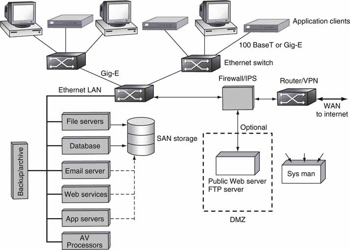
Figure 2.3 illustrates how many simultaneous, real-time video streams of different rates can fit into the listed pipes. At the top of Figure 2.3 is uncompressed 1080i HD (see Glossary) at 1.194 Gbps image payload data rate. Standard Gigabit Ethernet cannot carry even one stream of this format. The bottom of Figure 2.3 shows that SONET OC-192 can carry ~10,000 streams of Web video (see Appendix F). The packing densities are ideal, and a realistic packing may be 70 percent of these values due to a variety of link, transport, and format overheads.
FIGURE 2.3 Filling LAN/WAN pipes with video streams. Not to scale, ideal, no overhead.
Compression increases packing density greatly. Fully uncompressed digital cinema at so-called 4 K × 2 K resolution reaches ~9.6 Gbps, and some vendors use exotic InfiniBand links to move the images. Using MPEG2 compression, the same program can fit nicely into a 19.3-Mbps ATSC pipe. Newer HD compression methods can squeeze even more, reaching ~8 Mbps—a whopping 1,200:1 bit savings, albeit with a loss of the pristine quality.
2.1.8 Systems Management and Device Control
Element management methods are de rigueur; otherwise, chaos would reign in the IT center. covers systems management but especially in the context of AV/IT systems. A/V device control is not commonly practiced in a traditional IT center. However, the world of scheduled broadcast TV requires the coordinated recording and playback of many video frame-accurate signals. As such, a dedicated class of application called automation is commonly applied to this end. Device automation is considered in Chapter 7.
2.1.9 Software for All Seasons
At every layer in Figure 2.2, software plays a major role. The software may be classified into the following domains:
• Application and services related
• Operating systems (OS) for clients, servers, and other devices
• Middleware protocols for client and server communications
• Web services
• Programming frameworks
These technologies work hand in hand to complete a solution. These domains are discussed in Chapter 4. See (Britton) for more information too.
2.2 STANDARDS
It has been said that the nice thing about standards is that there are so many to choose from. So true—and for good reason. Without standards—and lots of them—interoperability would be hopeless. Figure 2.2 could never exist (with heterogeneous components) without standards. Based on our personal experience, sitting through hundreds of hours of debates and the due diligence of standards development, we know the pain is worth the gain. Figure 2.4 outlines a short list of standards bodies, user groups, and industry associations that are active in both IT and A/V spaces.
FIGURE 2.4 World of AV/IT standards.
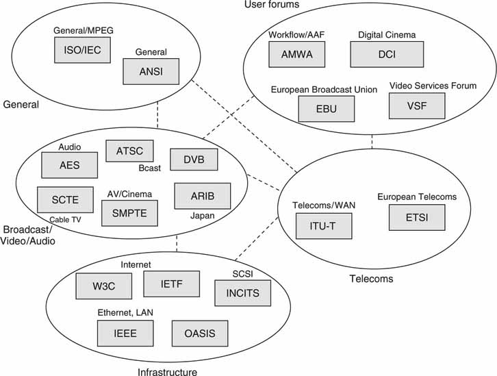
The mother of all standards bodies for A/V (broadcast, post, and cinema) is the Society of Motion Picture and Television Engineers (www.smpte.org). The Audio Engineering Society (AES) also contributes a significant effort. The International Telecommunications Union (ITU) is the world’s largest telecom body, and the ISO/IEC (two separate bodies that cooperate) has developed many standards, with MPEG and JPEG being the most significant for our space. The European Telecommunications Standards Institute (ETSI) works in fields that are germane to European interests, such as the DVB broadcast standards in association with the EBU. The IEEE and Internet Engineering Task Force (IETF) have developed thousands of standards (request for comments, RFCs) for networking interoperability. The W3C contributes important recommendations, such as XML, HTML, SVG, MathML, SMIL, Timed Text, and Web services. Among user groups, the Advanced Media Workflow Association (AMWA) is responsible for the Advanced Authoring Format (AAF) and is also creating recommendations for flexible media workflows using AAF, MXF, Web services, and SOA principles.
One new activity, sponsored by the W3C, is “Video in the Web.” The goal of this activity is to make video a “first class citizen” of the Web. The group has goals of building an architectural foundation that enables the creation, navigation, searching, linking, and distribution of video, effectively making video an integral part of the Web. Today, video is an afterthought, a dangling object forced to fit as needed. One goal is to standardize methods to identify spatial and temporal clips. Having global identifiers for clips would allow substantial benefits, including linking, bookmarking, caching, indexing, and displaying associated metadata. Not one of the existing solutions is fully satisfactory.
Many of these bodies have liaison connections to other bodies, and the dashed lines in Figure 2.4 indicate these relationships. For example, every SMPTE standard may have a corresponding ANSI (U.S., master body) standard. Normally, user groups have no power to set standards but they can make recommendations that sometimes become de facto standards, much like what AAF has become for edit decision list exchange. Not all liaison connections are shown in Figure 2.4.
Standards are the fabric that hold modern IT systems together. If you want to know more, most of the standards bodies have Web sites in the form of www.NAME.org. Some of the standard documents are free for the asking (such as the IETF; learn about TCP, for example, by downloading RFC 793), whereas others require payment (such as SMPTE and the ITU) per document. Many professionals in the broadcast and cinema industry subscribe to the SMPTE CD-ROM, a collection of all their standards for easy access.2
Of all the standards groups, SMPTE is the most active in video systems and digital cinema standardization. To keep in tune with SMPTE activities and receive its excellent Imaging Journal, consider becoming a member (www.smpte.org). The following is a summary of the work efforts (obtained from SMPTE documents) of the technology committees that develop standards.
2.2.1 General Scope of Technology Committees
To develop SMPTE engineering documents, review existing documents to ensure that they are current with established engineering practices and are compatible with international engineering documents where possible; recommend and develop test specifications, methods, and materials; and prepare tutorial material on engineering subjects for publication in the SMPTE Imaging Journal or for other means of dissemination benefiting the Society and the industry.
2.2.2 The Eight SMPTE Technology Committees
Essence 10E —The general scope as it applies to electronic capture, generation, editing, mastering, archiving, and reproduction of image, audio, subtitles, captions, and any other master elements required for distribution across multiple applications.
Applications Committees
Film 20F—The general scope as it applies to application of mastered essence to theatrical film distribution, including media and component creation, marking, laboratory methods, reproduction, packaging, projection, and related topics; additionally, film capture, editing, and recording.
D-Cinema 21DC—The general scope as it applies to application of mastered essence to theatrical digital distribution, including compression, encryption, wrapping, marking, packaging, media, logging, playout, projection, reproduction, and related topics.
Television 22TV—The general scope as it applies to application of mastered essence to television distribution, including compression, encryption, wrapping, marking, packaging, media, control, display presentation, reproduction, and related topics.
Broadband 23B—Application of mastered essence to electronic broadband distribution including compression, encryption, wrapping, marking, packaging, tracking/control, presentation, reproduction, and related topics.
Infrastructure Committees
Metadata/Registries 30MR—The general scope as it applies to definition and implementation of the SMPTE Registration Authority, used to identify digital assets and associated metadata. Additionally, the common definition of metadata semantic meaning across multiple committees.
Files Structures 31FS—The general scope as it applies to definition of common wrapper structures for storage, transmission, and use in the carriage of all forms of digital content components.
Network/Facilities Infrastructure 32NF—The general scope as it applies to definition and control of elements supporting the infrastructures of content production and distribution facilities, including file management, transfer protocols, switching mechanisms, and physical networks that are both internal and external to the facility, excluding unique final distribution methods.
2.3 A/V MEDIA CLIENTS
Looking again at Figure 2.2, let us morph it slightly to give it a more media centric personality. Without changing anything in Figure 2.2, we can add the notion of A/V by defining the A/V application client. So, consider the top level to be a mix of A/V clients and non-A/V clients. The necessary traditional A/V routing infrastructure is not shown in Figure 2.2 and is left out to simplify the overall diagram. See Chapter 10 for a discussion of a more dedicated, fullfeatured, AV/IT system based on the principles developed in this book.
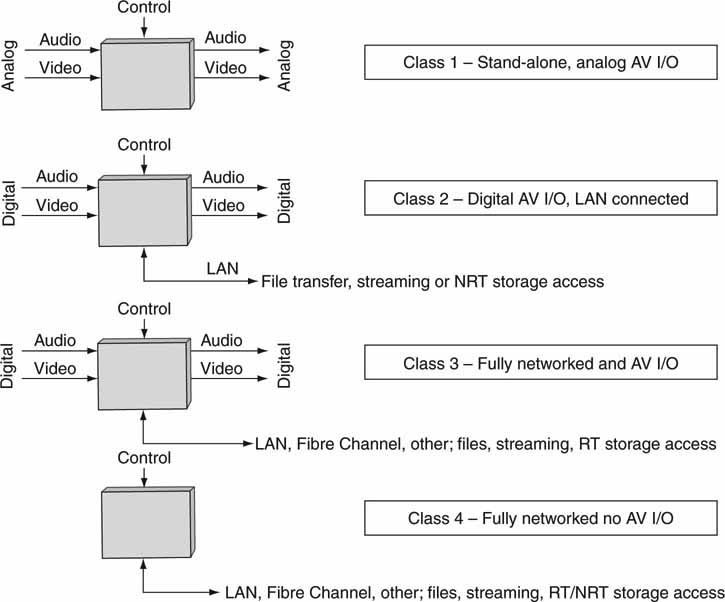
Broadly, there are four different classes of A/V client. Figure 2.5 shows their general I/O characteristics. The I/O notation is abbreviated, as time code signals and video reference inputs are omitted because they are not relevant to our immediate discussion. Also, the definitions are not meant to be rigid. Other hybrid combinations will exist. For example, clients with digital A/V inputs but no outputs or vice versa (ingest stations, cameras, etc.) are not specifically shown. The point of the four classifications is to discern the major client types and their characteristics. Let us consider each class and its applications. Also, no one class is superior to another class. Each has its strengths and weaknesses depending on the intended application. Some clients also have management interfaces, but these are not shown to simplify the diagrams.
FIGURE 2.5 Four classes of media clients.
2.3.1 Class 1 Media Client
The simplest class, class 1, is shown for completeness. It is all analog I/O (composite, component video), standalone with no network connection. It is the legacy class of A/V client and includes VTRs, analog amplifiers, linear switchers for edit suites, master control stations, special effects devices, and so on. This class has gone out of favor; it does not take advantage of digital or networked advantages. Still, there are many facilities with rooms filled with these devices in legacy A/V systems.
2.3.2 Class 2 Media Client
Class 2 is distinguished with the inclusion of coax-based serial digital interface (SDI) I/O for A/V connectivity and LAN connectivity. The LAN port may be used for file exchange and A/V streaming but not access to networkable RT storage by definition. Support for device-internal storage is common. Audio I/O is also included using the AES/EBU interface.
A sample of this class of client is the Sony IMX eVTR, which is an MPEG-based tape deck with SDI I/O and a LAN for MXF file export. Another example is the Panasonic P2 Camera with LAN (and removable Flash memory card) for exporting stored clips. Consider, too, the stalwart “small” (or configured as such) video server. Doremi Lab’s V1 server, Harris’s Nexio AMP, Avid’s Thunder, Omneon’s MediaDeck, and Thomson GVG’s M-Series iVDR are all class 2 devices with internal (or bundled) storage. Graphics devices such as Chyron’s Duet family, Inscriber’s Inca family, and Avid’s Deko family are also examples of class 2 devices. True, some of them may also be optionally attached to external real-time storage. In this case, these devices are considered class 3 devices (see for more information on the workhorse video server).
Other examples of class 2 devices are the countless models of standalone nonlinear editors (NLE) from many vendors. They normally have digital I/O and LAN to access files over a network. Most A/V test equipment is of class 2 but may not have any A/V output ports. The class 2 device was the first to bridge the traditional A/V and IT worlds back in the mid 1990s. At the time, it was groundbreaking A/V technology.
2.3.3 Class 3 Media Client
Class 3 is a fully networked device; it is a turbocharged class 2. It has not only SDI I/O, but also real-time access to external networkable storage. Of course, it also has LAN access for file exchange and streaming. The access to real-time external storage is the major differentiating characteristic of this class compared to class 2. Storage connectivity may use one or more of the following methods with current top data rates:
1. Fibre Channel (up to 2/4 Gbps per link)—SAN related.
2. LAN using Ethernet (up to 10 Gbps)—NAS and SAN related.
3. IEEE 1394 and USB 2.0 for connecting to small, local storage systems.
4. This mode offers limited network access to storage.
These methods are discussed in greater detail in Chapter 3A. Methods 1 and 2 are in heavy use in the IT infrastructure and are crucial to building any AV/IT system. IEEE 1394 and USB 2.0 are limited in their range and network-ability, but they find niche applications for low-cost clients.
In theory, networked clients can access storage from any location. This is a powerful feature, and it enables A/V I/O to be placed in the most convenient location independent of storage location. This freeness of location has its tradeoffs: an excellent link QoS is required to connect the client with the storage. Nonetheless, some systems will take advantage of this leverage point and more so as technology matures. Some class 3 devices also have internal HDD storage.
A/V data storage systems are core to the new media facility. There are many ways to construct these systems, they come in a variety of forms, and they allow for whole new workflows that were impossible just a few years ago. These aspects are discussed in Chapters 3A, 3B, and 7. Of course, relying on data storage systems to keep all A/V digital assets represents a major shift in operations: no more videotapes to manage and no more lost digital assets (if managed properly). There are several schools of thought regarding storage access by a client or server. Some of the methods are
A. Networkable RT storage pool available to all authorized attached clients. Classes 3 and 4 use this.
B. Networkable NRT storage pool available to all authorized attached clients. NRT storage has a relaxed QoS compared to RT storage. Classes 2 and 4 use this.
C. Islands of NRT storage. This is like B except there is not one consolidated pool of storage.
Method A is used with class 3 and 4 clients. Methods B and C are more appropriate for class 2 and 4 devices but may also apply to class 3. In Method C, files may reside on various file servers or arrays throughout a facility. If this occurs, then the asset management may become a serious nightmare, due to the balkanization of resources. In fact, most modern systems use either A or B for their design methodology.
The distinction between RT and NRT is important in several regards. RT storage is used by clients for streaming A/V processes such as recording and playout. NRT is used by clients for file transfer, offline A/V processing, metadata access, database access, and so on.
Large multichannel video server I/O devices are good examples of class 3 clients. Instances are Avid’s AirSpeed, Harris’s Nexio AMP server, Omneon’s Spectrum Media Server, the SeaChange Media Client attached to its Broadcast Media Library, and Thomson/GVG’s K2 media client/server system.
Other examples are networked nonlinear editors: Apple’s Final Cut Pro (Final Cut Studio too), Avid’s Media Composer family, Quantel’s family of sQ editors, and others. This class of media client offers the most flexibility compared to the other classes.
The digital audio workstation (DAWS) has unique requirements as a class 3 device. Many such devices (ProTools from Avid, or Logic from Apple, for example) support 192 simultaneous audio tracks at 48 KHz. This requires 26 MBps raw throughput. For sure, one HDD can support this rate. However, when it is divided among 192 file accesses, this is problematic due to possible small file chunk R/W and possible fragmentation issues. The bottom line is that a DAWS places a demanding I/O workload on a typical storage system.
2.3.4 Class 4 Media Client
Class 4 is a class 3 or 2 device without any A/V digital I/O. This client type is a fully networked station that does not have a need to ingest or play out A/V materials. Some class 4 stations may use NRT file transfer for importing/exporting files. Other stations may access a RT storage pool, whereas others may support streaming.
Examples of this client type include visual content browsers (low-rez normally), reduced functionality NLE stations, graphics authoring (Adobe Illustrator and Photoshop, for example) QA stations, asset managers, file gateways, file format converters, some storage, DRM authoring stations, file distribution schedulers, A/V processors, and displays. One special version of this client type is a control device that sends operational commands to other clients to record, play, route, convert, retrieve, and so on. Importantly, no A/V data pass through a control-type media client. Automation vendors offer a variety of media client control devices.
Another special case of this class is a software service such as a Web service. The service (with no UI) may perform a data conversion of some nature. This is covered in more detail in Chapter 4. Viewed in this light, the term client is not the ideal moniker but will suffice for our discussions.
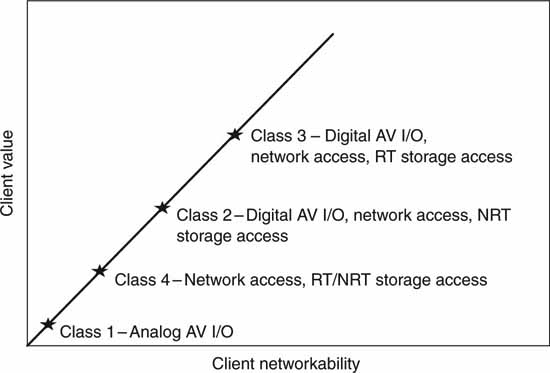
2.3.5 The Classes in Perspective
Figure 2.6 is a simple chart showing the value of networked clients. The class 3 client is the most useful due to its fully digital nature and networkability. The price/performance ratio, however, will always be a selection criterion, so all client classes will find ample use in video systems as designers seek to drive down the total cost. In general, class 4 is the least expensive from a hardware point of view, and class 3 is the most expensive. Of course, the software costs per device can range from insignificant to very expensive, so there is no simple way to classify the price/performance across all classes of clients. In the final analysis, classes 2–4 will find ample use across a wide range of new video system designs.
FIGURE 2.6 The relative value of media clients.
2.4 FILE TRANSFER, STREAMING, AND DIRECT-TO-STORAGE CONCEPTS
As mentioned in Chapter 1, three methods are key to moving A/V information in a video system. Most client types may use combinations of these methods. Figure 2.7 shows a system that has all three types of A/V data-moving means. When you are considering the three, you may compare them against each other in three pairs or consider them separately by their own standalone merits. Analyzing the methods by direct 1:1 comparisons (files versus streaming, files versus direct to storage, direct to storage versus streaming) is a bit tedious and somewhat obscures the overall trade-offs. To complicate things even more, because direct to storage may be NRT or RT access, our classification will analyze each method separately with some 1:1 for the most important characteristics.
FIGURE 2.7 Streams, file transfer, and storage access.
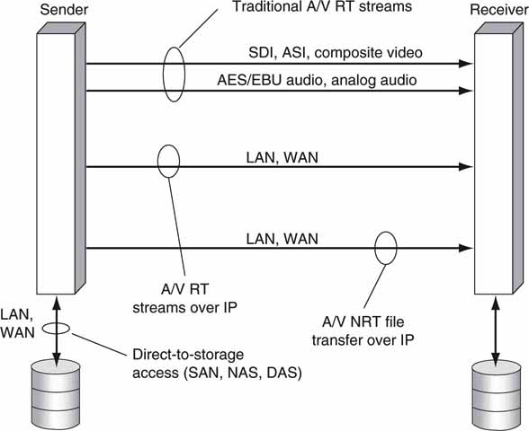
In summary, the high-level characteristics of each method are
• File transfer—Move files from one device to another (or point to multipoint). NRT transfers are easy to implement using FTP or HTTP, have no geographic limitations, and have 100 percent guaranteed file transfer.
• Streaming A/V—Stream data from one element to another (or point to multipoint), usually in real time. Traditional A/V streaming (SDI, composite) is common in video systems. IT-based streaming is mature as well but is used mainly for content distribution to end users. Voice over IP (VOIP) is a form of audio streaming.
• Direct to storage—Random read/write data access by a storage attached client. Attached clients may have access to a clustered file system for a full view of all stored files. Storage access may be NRT or RT. Of course, RT access is more demanding on the connect infrastructure. Storage access may be via DAS, SAN, or NAS methods. See Chapter 3B.
When you are transferring, streaming, or storing, it is wise to know the storage and data rate appetite of the A/V data structures. Table 2.1 outlines some popular formats and their vital statistics. See Chapter 11 for a discussion of A/V formats.
Table 2.1 A/V Storage and Data Rate Appetites
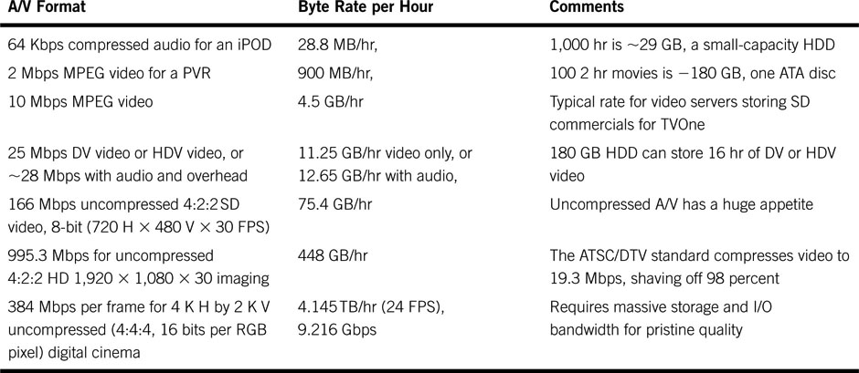
It is always good to have a rule of thumb when computing storage requirements. The best metric to memorize is the one in row 3 of Table 2.1. By knowing that 10 Mbps video requires 4.5 GB/hr, you can easily scale for other values because of the convenient factor of 10 scaling.
So 1 hr of DV requires 28/10 * 4.5 = 12.65 GB/hr. Many of the chapters in this book refer to A/V storage and bandwidth requirements, so it is a good idea to become familiar with these stats. Please note that Mbps means megabits per second and MBps means megabytes per second. A lowercase b represents bits and a capital B represents bytes—8 bits.
When you are building an AV/IT system, which method is best to achieve the most flexible workflows—file transfer, streaming, direct to storage, or some hybrid combination? What are the trade-offs among the methods? Let us consider these questions.
2.4.1 File Transfer Concepts
File transfer should be viewed as a hierarchy of steps or processes. One threelayer segmentation for the layering is as follows:
• Top—Scheduling, batching, file audits, reports, other metrics. These are useful for the what/who/when/where of transfers. See companies such as Signiant and FileCatalyst for examples.
• Middle—This is a transaction step for establishing the file transfer between two entities. Elements such as formal setup, initiation/terminate, security, metadata associated with the file, negotiation of transfer protocol to be used (FTP, HTTPS, etc.), restarts, error recovery, and more. See SMPTE standard 2032 (Media Dispatch Protocol, MDP) for an example of this function.
• Bottom—Protocol for actual file transfer. This could be FTP, HTTP, HTTPS, or another choice. Considerations for performance, security, and reliability are made at this layer.
The discussions to follow address the lowest layer for the most part, but other layers are covered in passing.
Figure 2.8 is used as the basis for our discussion. Clients A/B/C/D can all send and receive files. Frankly, each of these devices may also be a server, but let us use the client name for now. The file mover block is some sort of external control logic (automation system) that directs NRT file movement from a sender to a receiver(s). Additionally, individual clients can pull or push files from/to other clients in a peer-to-peer arrangement. Files can be transferred in a point-to-point or point-to-multipoint fashion. Each client has local storage of various capacities. File transfer between a source and a destination is often referred to as “store and forward,” although the moniker is losing favor. The file mover has the master database of the location of all files (or can locate a file using queries as needed). Client A may be the master file repository, but this is not a requirement for a file-based architecture.
FIGURE 2.8 NRT file transfer topology example.
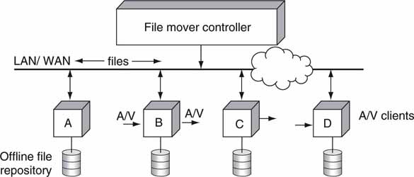
Table 2.2 lists the general characteristics of a file transfer. Although not cited, many of the features of file transfer are different from either streaming or direct-to-storage methods. If you had to deliver an elevator pitch summary of file transfer, the top three points would be as follows: 100 percent error-free delivery is possible, NRT delivery normally, point-to-point is the most common mode.
Table 2.2 Feature Set for General-Purpose File Transfer
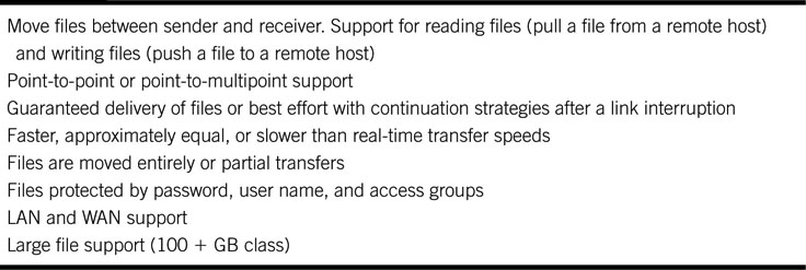
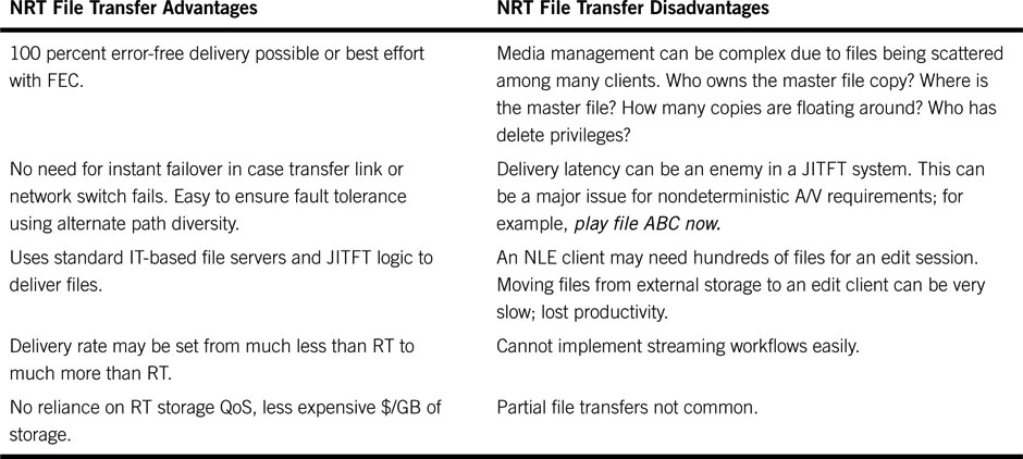
Table 2.3 (in reference to Figure 2.8) outlines the foremost advantages and disadvantages of the file transfer method. One acronym needs explaining: Just in Time File Transfer (JITFT). In a file-centric system, a client may need a file for a critical operation at a certain time of day. The file mover, for example, may schedule the file transfer (move a file from client D to client B) such that a needy client receives the target file “just in time” as a worst case. There is a delicate balance between sending files too soon (hogging the client’s local storage) and too late (may miss a deadline due to the NRT nature of file transfer). JITFT is a way to think about these issues.
Table 2.3 Advantages and Disadvantages of NRT Transfers
MOVING FILES: IT IS TIME VERSUS MONEY
When you are transferring an HD or SD file, you may choose a low rate link to save money. Slow links result in long delivery times—possibly many hours. However, an improved QoS (more money) can reduce the delivery time—several seconds is achievable. So, as with many things in life, money saves time.
The NRT moniker is a bit vague in terms of the actual file transfer time. For some systems, a 1/10 file transfer speed (1 min of program material takes 10 min to move) is sufficient, whereas other system designs may require × 10 file transfer speed. The rated speed of transfer and the infrastructure performance are intimately connected. This topic will not be studied in detail, but it should be obvious that × 10 file transfer speed requires a storage and link QoS approaching RT, if not much better. Aspects such as component failover during a fast transfer need to be accounted for to guarantee JITFT performance. The analysis in Table 2.3 assumes that NRT < RT in terms of speeds. If NRT is defined as >> RT, then many of the advantages/disadvantages are inaccurate. Of course, a JITFT-based design can also use a wide mix of NRT speeds, making the system design more difficult in terms of QoS and failover requirements.
The advantages/disadvantages comments in Table 2.3 are not meant to be row aligned; i.e., there is not necessarily a correlation between the advantage and the disadvantage on the same row.
2.4.1.1 Reliable File Transfer Techniques
The bedrock protocols for file transfer over networks use the TCP, UDP, and IP families. TCP is a packet-reliable protocol and is widely used. UDP is a “send-and-hope” methodology and also finds wide use. Table 2.4 outlines the chief methods used to transfer files using both TCP and UDP. Most of the entries support multiparty transfers. Some are best-effort delivery using an FEC, and some offer 100 percent error-free delivery. Refer to Chapter 6 for more information on IP, TCP, and UDP.
Table 2.4 File Transfer Method Classifications
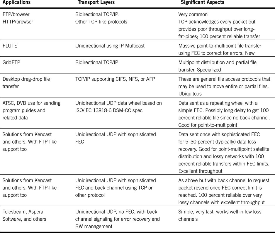
Let us consider the first four methods in Table 2.4. FTP (RFC 969) is the granddaddy of all file transfer methods and is used daily to move millions of files. In practice, FTP does not formally support partial file transfer (start-end points within a file) or point-to-multipoint transfers. To reduce the deficiencies of FTP, the IETF is developing FLUTE - RFC 3926. This is a new file transfer protocol for doing point-to-multipoint transfers, and it supports a massive number of simultaneous receivers over unidirectional IP channels. Because there is no back channel, each receiver uses FEC methods to recover modest amounts of data lost (if any) during transmission.
The third row in Table 2.4 outlines GridFTP (www.globus.org). This is a protocol for use in grid computing (Appendix C). It extends the standard FTP protocol with facilities, such as multistreamed transfer and partial file transfer. The effort is currently not under the sponsorship of the IETF. Files may also be transferred using the desktop drag-and-drop method common to many computer applications. In this case, the underlying protocol is not FTP, but usually CIFS, NFS, AFP, or another remote file access protocol (see Chapter 3B). It is apparent that there are various file transfer methods in use, but garden-variety FTP does the lion’s share of work today for simple point-to-point applications.
The Ubiquitous FTP/TCP Method
Developed in the 1970s at UC Berkeley, the File Transfer Protocol (FTP) is a wonderful tool for point-to-point file transfers using bidirectional links. Figure 2.9 shows the basic client/server FTP arrangement. Separate logical control and data connections are shown. In general, the client establishes a TCP control connection over a LAN/WAN with the server side. The server may accept more than one client connection (sometimes hundreds). Commands are sent to request the server to transfer files or accept files.
FIGURE 2.9 FTP client and server with control and data logical connections.
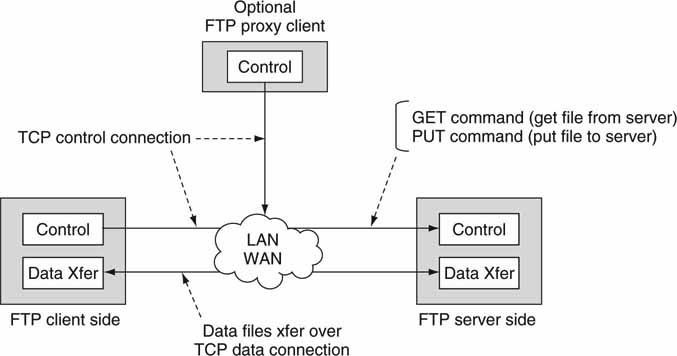
Typical commands are GET_File to request a file transfer (server to client) and PUT_File to send a file (client to server). The server responds by pushing or pulling files over the data connection. No file data move over the control connection. Of course, using TCP guarantees a 100 percent correct file transfer even over congested networks. FTP works quite well over a confined LAN, and transfer speeds can be exceptional. Transferring large files (gigabytes) is always a challenge if the link is slow (or long) because the transfer can take many hours.
For long-distance transfers, TCP is not ideal and, in fact, can be as much as 100 times slower than alternative transport means. Why is this? Simply put, TCP’s reliability scheme limits its data throughput inversely with network latency and packet loss. When packet loss is detected, TCP reduces its “congestion window” size exponentially. The window size defines the maximum number of bytes in the transmission pipeline before the receiving end acknowledges receipt to the sender. After recovering from a packet loss, TCP increases the window linearly and slowly. Hence, aggressive back-off and slow ramp-up limit the TCP throughput considerably. See Chapter 6 for a discussion of how and why this limits throughput.
Another important aspect of FTP is a supported mode called “proxy client.” Many everyday FTP transactions involve the client and server as discussed. But what if a third party (the proxy; for example, an automation system) needs to initiate a file transfer between the client and the server? How is this done, and does the proxy receive any file data? In Figure 2.9 the proxy client is shown with only a control connection.
Consider an automation system (the proxy client) requesting an archive system (the FTP server) to send a file to an on-air video server (the FTP client). The proxy client initiates the transaction, and file data move between the two end points. From the standpoint of the FTP server, it is blind to where the request originated. The request could have come from the proxy or the standard FTP client. See RFC 959 (Figure 2.9) for more information on FTP and the proxy client.
Formally, FTP does not support partial file transfer, say, from a mark-in point to a mark-out point in the file. This hobbles applications that want to transfer 1 min out of a 60 min program, for example. Some vendors have used the optional FTP SITE command for this purpose. This method is being copied by others, and it may become a de facto standard. One FTP application vendor that supports the proxy client mode and the SITE command is FlashFXP (www.flashfxp.com), but there are others. Stepping away from TCP and its cousins, let us consider the fourth row from the bottom in Table 2.4.
Data Wheel File Transfer Method
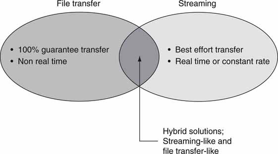
Consider the case of transferring a single file to thousands (or millions) of settop boxes and televisions over a satellite or cable system. This is the case for the distribution of the electronic program guides. It is not practical to use a packet-reliable protocol such as TCP, so the Digital Audio Video Council (DAVIC, active in 1994–1997) invented the data carousel as a repeating data stream. Data are sent in packets (UDP in functionality and concept) to all end points with a modest forward error correction (FEC) to correct some errors at the receiver point. Data repeat as a wheel, so if, say, 5 percent of the data file was not received on the first pass, then the missing packets will likely be recovered on the next or subsequent passes. The data transfer rate may be very slow, but the patient receiver will be rewarded with a 100 percent data file, given sufficient passes of the data wheel. DVB and the ATSC standards specify this method for sending “files” to set-top box receivers. This protocol is an example of a hybrid file transfer and data stream. Figure 2.10 shows the features of a transport means that is part pure file transfer and part streaming. Given the limited use of this protocol, other more efficient means have been invented, as referenced in the last three rows of Table 2.4.
FIGURE 2.10 File transfer and streaming domains.
IP MULTICAST
IP Multicast is a bandwidth-efficient method (and set of standards) for moving data across a network to mul tiple locations simultaneously. Multicast requires that all the IP switches in the network cooperate. See http://en.wikipedia.org/wiki/Multicast for a tutorial on the subject. It is not commonly implemented for professional A/V applications and is slowly gaining maturity.
Sophisticated FEC Methods
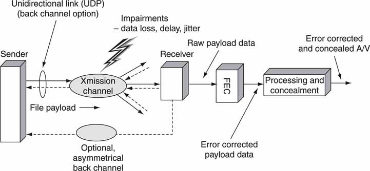
Forward error correction is a general means to correct for a fixed percentage (say, 10 percent) of packet loss at the received end of a file transfer without needing to contact the sending site for retransmission. Files may be sent over unidirectional links (UDP in concept) at much greater rates than TCP will allow, but UDP lacks the reliability layer of TCP. Also, UDP naturally supports point-to-multipoint transfers. Figure 2.11 outlines a general system that relies on UDP for file transmission and FEC to correct receive errors. All errors within the correctable range will be repaired with 100 percent reliability. A return channel may be used to augment the FEC for requesting packet resends when the loss exceeds the correctable range (>10 percent, for example).
There is no free lunch, however. To correct for, say, 20 percent data loss, the FEC overhead is at least 20 percent and usually more. The FEC overhead may be located at the end of every packet/data block or distributed throughout the data stream. Algorithm designers choose from a variety of methods to correct for errors. The common audio CD uses a data-recording method called eight to fourteen modulation (EFM). When this is coupled with Reed-Solomon coding (plus data interleaving!), burst errors of up to 3,500 bits (2.4 mm ~ 0.1 inch wide defect on media) can be completely corrected. Even a horribly scratched audio CD (or video DVD) will likely play with 100 percent fidelity thanks to Mr. Reed and Mr. Solomon.
FIGURE 2.11 File transfer delivery chain over unidirectional links with FEC.
There are several methods that provide for error correction: Hamming codes, Fire codes, Reed-Solomon, BCH codes, Tornado codes, and countless proprietary codes like the ones from Kencast (www.kencast.com); for example, see (Morelos 1991). See Chapter 5 for examples of how RAID works to correct for errors from disk drives. The overall winner in terms of efficiency for burst error correction is the Reed-Solomon coding scheme, although other coding schemes may be more efficient under a variety of operating modes. These methods often support the common FTP programming interface semantics (GET, PUT, etc.), although not the FTP protocol layer.
Just how good is the Reed-Solomon FEC? In the R/S world, N total data symbols with K user message symbols have an FEC overhead of N – K data symbols. So if N = 204 and K = 188, then 16 “overhead” symbols are needed to per form the FEC correction. It turns out that (N – K)/2 symbols may be corrected by the RS algorithm. If each symbol is a byte, then for this case 8 bytes may be corrected with an overhead of 16 bytes. True, this method is not 100 percent efficient (one bit overhead per corrected bit would be ideal), but it is relatively easy to compute, good at large block error recovery, and well understood.
Looking at Figure 2.12, we can see that a 16-byte electronic correction code (ECC) is appended to the end of a 188-byte data payload for this example. This is an example of the ubiquitous DVB-ASI transport stream format. The 16-byte overhead can correct for up to 8 corrupted payload bytes as applied by the FEC algorithm. Using more ECC bits corrects for more corrupt payload bits. But what if not all the errors can be corrected? Of course, if the receiver can ask for a resend, then the bad bits may be recovered. This raises issues such as the latency for the resend, the logic to do this over a field of, say, thousands of receivers, the requirement for a back channel, and so on. Under some circumstances, concealing an error when the FEC has run out of stream may be better than requesting a resend of data.
FIGURE 2.12 Using FEC to correct errors: An example using R/S.
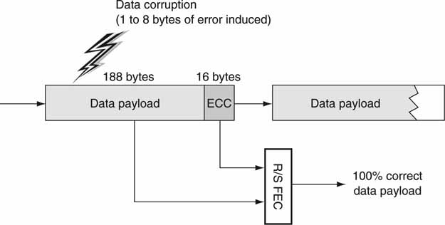
An example of this is to silence a portion of an audio track during the period of corrupt data samples. Another case is to replicate the previous video frame when the next frame is corrupt. Muting, duplicating information, or estimating has its limits naturally, but it works remarkably well when the method is not overused. The audio CD format uses a combination of FEC and error concealment to reconstruct errors in the audio stream. Of course, it is not feasible to conceal some data errors any more than it is practical to estimate the missing digits in a corrupt phone number (or metadata or compressed coefficients and so on). As with all methods to recover data, the designer needs to use prudence in applying the right mix of FEC, resend, and concealment. Concealment can be applied only after A/V decompression has occurred (if any) because it is nearly impossible to conceal most errors in the compressed domain.
File Transfers Using UDP Without FEC
The last row in Table 2.4 includes methods using UDP without any FEC for reliable data payload transfers. During the course of the file transfer, the receiver acknowledges only bad or missing packets using a separate TCP-based (or UDP) message sent to the sender. The sender responds by retransmitting the requested packets. The HyperMAP protocol from Telestream (www.telestream.net) is an example of such a protocol. UDP payloads with negative acknowledgments can be very efficient, especially over a channel with low loss or in a point-to-multipoint transfer. A channel with 3 percent packet errors can achieve ~97 percent of the throughput of the raw link. HyperMAP has some added A/V-friendly features too, such as resume interrupted transfers, resume a transfer from a different location, and pause/resume a transfer. It beats FTP/TCP in terms of performance at the cost of being a proprietary protocol. There are many variations on this theme in use today.
Another way to speed up data transfers is to use a WAN accelerator. This small appliance is placed at each end of a WAN link and uses protocol tricks to increase date transfer rates. How is this done? One method is to replace any TCP streams (as used by FTP) with UDP streams and appropriate error recovery methods. The protocol remapping techniques are non-standard, but the appliances hide this fact from all upper-level user applications. It is not unusual to get a 30–100×-improvement in data transfer speeds across a long distance WAN connection.
This class of products falls under the umbrella of wide area file services (WAFS). Besides TCP speedup, WAFS appliances also increase the performance of storage access over a WAN. See Chapter 3B for more insights on WAFS.
SWARMS OF FILES
You likely have heard of iMesh, Kazaa, Morpheus, or other applications for file transfer across the Web. They are used commonly to transfer A/V files using peer-to-peer transfer—sometimes illegally. The reference to them is provided as an example only and not as an endorsement. Still, these programs are commonly used for legal file exchange as well. There is no file mover equivalent for these programs, and clients initiate and exchange files with other clients. One novel peer-to-peer transfer method comes from BitTorrent. Using the BitTorrent software, a client downloads pieces of a file from several clients simultaneously until all the pieces are collected. A “swarm” is a collection of clients all connected to share a given file. By each client sharing only pieces of a file, more clients can share and receive a given file simultaneously. See www.bittorrent.com for more information and links on swarming.
Choosing the Best Method
So which of the methods in Table 2.4 is the best? Well, the answer depends on your needs. FTP/TCP works quite well for short hops (roundtrip delay < than 20 Ms) within a campus environment. Very large FTP/TCP throughputs on the order of 350 Mbps and greater may be achieved over Ethernet-based LANs. FTP is the de facto standard for file transfer, and most equipment vendors support it. For wide area file distribution, FEC methods work very well and have wide industry acceptance. The proven fact that non-TCP transport layers can deliver files up to 100 faster is a huge impetus to use TCP alternatives such as UDP coupled with a powerful FEC (or with negative acknowledgments) or WAN accelerators.
2.4.2.1 QoS Concepts
Quality of service is a concept crucial to many aspects of A/V—both traditional and IT based. Typically, QoS metrics define the quality of transmission on any link that connects two points. Thus, the concepts apply to file transfer, streaming, and storage access. An Internet connection, a video link from a sports venue, or a satellite stream may all be classified by their QoS metrics. Of course, QoS concepts can be applied to just about any process, such as application serving or storage access. Specific metrics are applied as appropriate.
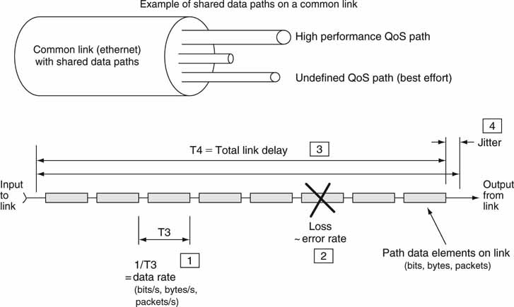
The big four QoS link and network parameters are data rate, loss, delay,and jitter (variation in delay). These metrics apply to digital paths only. Ideally, a 270-Mbps multihop SDI path QoS is 270 Mbps rate guaranteed, loss is near zero, delay is approximately wire speed, and jitter is near zero. The QoS of a consumer’s Internet3 end-to-end connection is more relaxed with variable data rates (DSL or cable rates), some packet loss (0.2 percent for traffic is typical), modest delay (~5 Ms for intracity end points), and some jitter expected (~20 percent of delay average). Aiming for an ideal QoS may be a waste of money if a relaxed QoS will meet your needs. After all, the tighter the QoS, the more expensive the link. Regardless of the QoS for any practical link, an error can occur in the received video stream. Despite SDI’s well-defined QoS, it always offers best effort delivery. Receive errors may be concealed in some manner.
Figure 2.13 illustrates the four key QoS metrics for an end-to-end network path. Figure 2.13 shows how each metric is measured in principle. Also, some links (such as Ethernet) may carry many different unrelated connections simultaneously—each with its own QoS requirements. Whenever paths share a common carrier, attention is needed to keep them separate and with no cointerference. Isolating paths is not easy because one rogue path (data bursting over their assigned limit, for example) can ruin the QoS of the entire link. It is normally left to the end point transmitting gear to meter data and set the QoS rate. Many WAN links meter data rates, usually at the edges, and will throttle data to their assigned range.
FIGURE 2.13 Network path QoS: The big four defined.
The required QoS of an A/V-related link depends on whether the link is used for file transfer or streaming video. These two methods are compared in the following section.
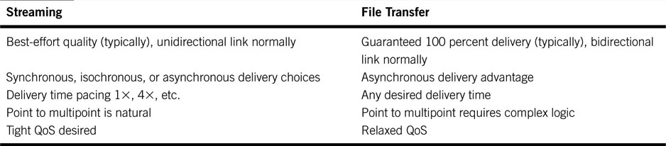
2.4.2 Streaming Concepts
In addition to file transfer, streaming is a second popular method used to move digital media between two or more devices. Five main characteristics highlight the differences between streaming and file transfer (see Table 2.5). Examples of streaming abound: digital TV broadcast over terrestrial and satellite links; traditional SMPTE 259M SDI and composite links; Intranet (campus) A/V streaming; and popular Web media as distributed by radio stations, news organizations, and other sources of streaming A/V.
Table 2.5 Streaming Versus File Transfer
Some links are designed to natively carry real-time streaming, such as the ubiquitous SDI, and, in the WAN sense, T1/E1, SONET, and other Telco links. Digital broadcast standards ATSC and DVB support streaming. Still others such as asynchronous Ethernet can be made to carry streams using appropriate IP-based protocols. More variations on the streaming theme are discussed later.
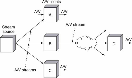
Each streaming method uses completely different means but achieves the same end result—namely, the best-effort (usually) delivery of real-time A/V materials to one or more receivers. In some applications, streaming may do the job of a file transfer and vice versa, so it is prudent to compare these two methods. Figure 2.14 shows a simple example of a point-to-multipoint streaming configuration. Let us consider each row of Table 2.5 (Kovalick 1998).
FIGURE 2.14 Real-time streaming topology example.
Normally, streamed content is delivered in a best-effort fashion. If there is no back channel and only a modest FEC is used, then there is no way to guarantee reliability. Of course, with a back channel, the quality can be outstanding, but streaming is implemented most efficiently without a return channel. If the packet loss is overwhelming, then the efficiency of FEC is lost. A streaming application with a heavy FEC or back channel use may indeed be considered a file transfer method, as Figure 2.10 indicates in the overlap area. Most practical streaming applications in use today provide for best-effort delivery.
Row 2 of Table 2.5 outlines the different timing relationships that a delivery link may use. Digital video streams can be isochronous, synchronous, or even asynchronous. These timing relationships are covered later in this section. Isochronous and synchronous connectivity put strict requirements on the QoS for the link.
Another important aspect of comparison is the delivery timing as listed in row 3 of Table 2.5. For live events, a RT-streamed link may be the only practical choice. But for many other applications (copies, distribution, archive, etc.), a NRT file transfer is preferred. In fact, choosing the delivery time adds a degree of flexibility not always available in streamed video. It may be prudent to do a program dub at 100 × without loss of quality or, to conserve resources, distribute a program at 1/10 real time. Of course, you can use streaming to mimic a file transfer, but the best-effort delivery of most streaming methods results in file transfer having the quality edge.
The point-to-multipoint nature of most simple streaming methods is difficult to match using file transfer (row 4 of Table 2.5). True, as shown in the section on file transfer, there are methods to do multipoint transfers, but they are sophisticated and not as simply implemented as streaming for the most part. Consider the case of the traditional SDI link. To send an SDI-based signal to, say, 10 receivers is a snap. Merely run the source SDI signal through a 1:10 distribution amplifier or use a SDI router with multiple ganged output ports. See Appendix I for insights into a novel multipoint streaming method.
Finally (row 5 of Table 2.5), the cost of networking infrastructure is dropping much faster than that of video-specific infrastructure. Networking components are following price curves that are tied directly to Internet infrastructure costs, as discussed in Chapter 1. In general, file transfer has the cost edge for NRT applications, as the associated QoS can be very poor and still achieve a 100 percent reliable file reception. Of course, a loose QoS may be used for RT streaming, but the rate, loss, delay, and latency specs must be accounted for. One example of this is Internet telephony or voice over IP (VOIP). VOIP is a RT streaming operation using modest QoS; therefore, some long-distance telephone calls have less than desired quality.
If you have followed the discussion to this point, then it should be apparent that file transfer and streaming both have a place in video systems design. File transfer has an overall edge in terms of guaranteed quality compared to streaming for NRT content distribution, but RT streaming beats file transfer when live programming is sent from a source to one or more simultaneous receivers. LAN-based streaming for professional applications is rare despite its everyday use over the Internet and business intranets. WAN-based streaming (point-to-point trunking) has found some niche applications. MXF has support for streaming and some early tests show promise. See (Devlin 2003) for more information on using MXF for streaming applications.
2.4.2.1 Streaming Delivery and Timing Methods
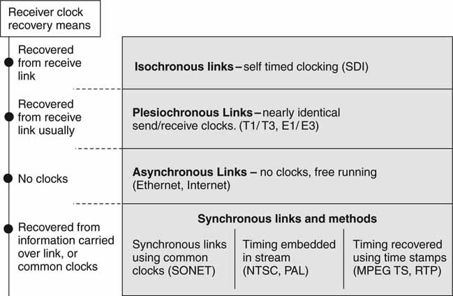
A streaming receiver should be able to “view/process” the received stream in real time. The notion of clocking is usually associated with a stream because the receiver normally needs knowledge of the sender’s time references to re-create the target signal. A good example of a timed stream is a typical NTSC/PAL broadcast TV signal. Another example is that of video moving over an SDI or composite link. Many Telcos offer A/V streaming wide area connectivity using the analog TV-1 service, a digital 45 Mbps compressed video service, or a 270 Mbps uncompressed service. Accessing Web video on a PC is normally a streaming operation (or progressive download). Streams can be sent over just about any kind of link if the appropriate (rate, loss, delay, and jitter) considerations are met. A stream may be sent over a path using the following forms of connectivity:
• Isochronous (equally timed bits) links. In this case the medium (SDI and AES/EBU links) has an inherent bit clock to guarantee precise timing relationships. The clock is embedded into the on-the-wire format. The transmit clock may be recovered directly at the receiver from the link’s data bit stream. In a well-provisioned link, there is zero data loss, very low jitter, and low delay. This link was designed with RT streaming as the goal.
• Synchronous (with time) links. With synchronous links, end-to-end timing coordination is accomplished using a systemwide common clock. SONET and SDH are good examples of synchronous links. See Appendix F for more information on telecom links. Streaming A/V over a synchronous link requires extra effort compared to using SDI alone, but low data loss, jitter, and delay can be achieved.
• Plesiochronous (almost synchronous) links. In this case the sender clock and receiver clock are not 100 percent locked, but are very closely in sync. Two plesiochronous signals are arbitrarily close in frequency to some defined precision. These signals are not sourced from the same clock and, after a time, they become skewed. Their relative closeness allows a switch to cross-connect, switch, or in some way process the signals.
• The inaccuracy of timing may force a receiver to repeat or delete data (video) in order to handle buffer underflow or overflows. Examples of these links are the ubiquitous T1/T3, E1/E3 telecom links. The clock drift specs are a function of the timing hierarchy as defined and used in the telecom world. If time stamp clock recovery methods are used in association with these links, true loss-free A/V streaming is possible.
• Asynchronous data links. Ethernet is a typical asynchronous link. True, it has a notion of clocking (100 Base-T has a nominal clock of 100 Mbps), but the timing is loose and there is no concept (normal use) of clocking coherence between Ethernet links. Streamed A/V may be carried over asynchronous links if the time stamp methods described for synchronous communications (see later) are applied. With error correction or using TCP/IP, excellent low loss and jitter characteristics may be obtained. One trade-off is typically long delays compared to the other links discussed.
It is possible to achieve outstanding A/V streaming quality using asynchronous or plesiochronous links if attention is given to coordinating the end point timing relationships. Let us call this technique synchronous communications.
Synchronous Communications
With synchronous communications, the timing coordination is accomplished by synchronizing the transmitting and receiving devices to a common clock signal by some means. The links may be tightly clocked (SONET/ATM), loosely clocked (Ethernet), or not clocked at all (Internet connectivity). Methods for a receiver to recover a sender’s clock are as follows:
• The sender and receiver use the same clock. They may use a GPS-based global clock, for example, or use independent Cesium clocks such that any frequency drift is inconsequential. Another method is to use the network time protocol (NTP, RFC 1305) at both ends. SONET is an example of a WAN link using common clocks. Alternatively, IEEE-1588 Precision Time Protocol (PTP) provides timing signals over IP/Ethernet and can achieve 10- to 100-μ s accuracy in campus networks. This accuracy is about one horizontal line of video (see http://ieee1588.nist.gov.). SMPTE and the EBU are co-sponsoring new standards for precision time distribution in the studio/facility environment. They should be available in late 2009 or soon thereafter. Refer also to the work from the IEEE’s 802.1 Audio/Video Bridging Task Group. This group is developing time-synchronized, excellent QoS, low-latency A/V streaming services through 802 networks. The standards are referenced as 802.1AS, 802.1Qat, and 802.1Qav (www.ieee802.org/1/pages/avbridges.html).
• Derive a clock from received embedded time stamps. This is commonly used for Web A/V streaming, MPEG broadcast (DVB, ATSC, and satellite) for home TV, and other applications.
• Derive signal timing from the received signal stream. A PAL or NTSC signal is designed so that a receiver may recover the sender’s “clock.” The common video composite signal also supports receiver timing recovery. A receiver uses the embedded horizontal and vertical timing information to re-create the sender’s notion of the same timing. If designed properly, a receiver can stay locked indefinitely to the sender’s clock references.
Note that synchronous end-to-end communications are not necessarily dependent on some sort of synchronous link. True, the tighter the link clocking, the easier it may be to stream A/V. But think of synchronous links and synchronous communications as different concepts. That is why it is possible to achieve respectable A/V live streaming over the Web—one of the most egregious examples of a non-synchronous network.
Figure 2.15 shows a segmentation of methods to achieve end-to-end streaming over links of various sorts. For most real-time streams, the receiver needs to recover the transmitter’s original sense of timing before the A/V can be viewed or otherwise processed live.
FIGURE 2.15 End-to-end communication methods for A/V streaming.
The SDI link has a special place in the heart of the video systems designer. It is possible to create a complete A/V system with thousands of SDI links all completely lock-stepped in sync (video line and video frame synced). As a result, live frame-accurate switching (camera choice or other source choice) between the various SDI links is a relatively trivial matter. Switching is not so easy when it comes to using the other links in Figure 2.15. See Appendix B for some insight into synchronizing multiple independent A/V signals from non-isochronous sources. Still, IT links can be used for many typical A/V streaming applications with proper care.
Push-and-Pull Streaming
There is one more aspect of streaming to contemplate before we leave the subject: stream flow control. There are two general methods to move a stream from a sender to a receiver: push it out from the sender without regard for the receiver or pull it from the sender under control of the receiver. A broadcast TV station operates using the push scenario. No end point receiver can throttle the incoming stream—take it or leave it. The sender must push the output stream with the exact flow rate that the receiver will consume it. In the second method, the receiver pulls data from the sender. A viewing PC asks for, say, the next 5 s of video, and the sender complies by sending it. When the receiver has consumed 4 s, it asks the sender for more and so on. This method allows for the receiver to control the stream precisely according to its needs (display video, for example). Frankly, push streaming is used most commonly. In fact, most Web-based consumer A/V streaming is UDP push based. One special use of pull streaming permits the receiver to pause, fast forward, or rewind a stream by commanding the sender to act like a virtual VTR. Of course, physics will not allow a receiver to fast forward a live stream.
Interactive Streaming
Interactive Web-based streaming (start, stop, pause, fast forward, rewind, etc.) requires a client feedback mechanism to control the source server. In Web applications, the real-time streaming protocol (RTSP, RFC 2326) may be used for this purpose. No A/V data are transported over RTSP; it is a stream control method. Rather, the real-time transport protocol (RTP, RFC 1889, 3550, and 3497) is used for streaming transport. RTP provides end-to-end network transport functions suitable for applications transmitting real-time A/V over multicast or unicast network services. RTP does not address resource reservation and does not guarantee QoS for real-time services. These protocols will find some use in professional, high-quality applications, especially for point-to-point trunking applications.
High-Quality, High-Rate Streaming
Many streaming applications are for low data rate, end-user needs. However, there is an application class for very high-rate professional “trunking” over IP networks. Point-to-point links between A/V facilities (sports, news, and campus events) have been provided for years using T3/E3, SONET/SDH, and other connectivity. These links can be very expensive and often require compressed A/V to reduce the data rate. With the advent of available IP access, several vendors offer SDI extenders over IP.
One such product is from Path 1 Networks (www.path1.com). The Cx1000 IP Video Gateway delivers uncompressed RT SDI (270 Mbps) over IP networks. The unit maps the SDI data input onto a 1 Gb Ethernet link, and a second remote unit unwraps IP data and outputs it on an SDI link, resulting in transparent trunking. The Ethernet link may be WAN connected for even greater reach. Using clock recovery and FEC methods, the gateway provides excellent QoS in the presence of link jitter (250 Ms) and packet loss.
Well, that’s it for the coverage of streaming. These concepts are referenced throughout the book and are fundamental to AV/IT systems. For more information on professional streaming methods and applications, refer to the Video Services Forum. This industry group specializes in streaming A/V transport technology (www.videoservicesforum.org).
2.4.3 Direct-to-Storage Concepts
Figure 2.16 shows a simplified plan of a shared storage model for attached clients. In this case, clients A/B/C/D all have RT read/write access to a single storage system. NRT access will not be analyzed in as much detail because NRT is a relaxed form of the RT case. In the RT case, external storage appears as local to each client. All files are stored in the same repository, and there is no requisite for files to be moved (file transfer) between clients or from the storage to a client. Individual clients may have local physical storage, but this is not a requirement. Individual clients may also be restricted from accessing all the available storage and from deleting files. User access rights and permissions may be set for any client to guarantee a well-managed storage system. With direct access to storage, clients have the ability to randomly access read/write data into any stored “file” in real time. For the shared storage model to be most effective, all clients also need to share a common file system. Let us assume this exists for our analysis. Clustered file systems (CFS) are discussed in detail in Chapter 3A and provide for a true file-sharing environment among attached clients. Without a CFS, only the storage hardware may be shared.
Regarding the RT aspect of storage, it can also come in different flavors. By strict definition, RT storage allows for A/V-stored data to be read/write in A/V real time without exceeding the loss, delay, and reliability specs for the system. Playing a Super Bowl or World Cup commercial ($2.2 million for 30 s) to air from RT storage will require a higher level of QoS than, say, supporting the QoS needs of a five-station edit system. As a result, the overall QoS of either an RT or NRT system is a strong factor of system requirements.
FIGURE 2.16 Real-time direct-to-storage topology example.
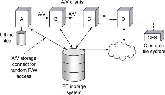
Table 2.6 lists the advantages/disadvantages of the shared storage model. An advantage in a row is not necessarily aligned with a corresponding disadvantage in the same row. Treat the columns as independent evaluations. To gain more insight, compare Table 2.6 to Table 2.3 and Table 2.5 on file transfer and streaming.
Table 2.6 Real-Time Shared Storage Access
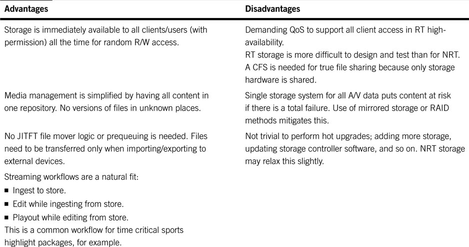
The biggest plus of the shared storage model is the fact that all clients have immediate RT read/write random access to all storage. This is not a feature of streaming or file transfer. Also, workflows may be designed in almost any form because files do not need to be moved before A/V operations can start. A general conclusion is that shared storage trumps file transfer, and file transfer trumps streaming for the majority of operational needs in an AV/IT facility. This conclusion must be taken in context. Sure, there are sweet spots for each method. If the application is live production, then streaming using SDI is required. In practice, facility SDI links are routed to provide access and reach. Also, file transfer is more appropriate than streaming for delivering files in NRT over unreliable links or long distance. Each method needs to be considered on its own merits and in relation to a particular target workflow. Examples of all methods are to be found in facilities worldwide.
2.4.3.1 Using File Transfer to Create a Virtual Shared Storage Model
Figure 2.8 shows each client with individual storage. Figure 2.16 shows a similar configuration but in a shared storage model. If the individual storage pools in Figure 2.8 all had identical file content, then each client would see the same files. At times, there is a design advantage for individual storage to act like shared storage. To put it another way, if Figure 2.8 smells and feels like Figure 2.16, then some aspects of data management and control are simplified.
How can the two figures be made to act as equals from the client perspective? One way is to mirror all file content on all storage in Figure 2.8. This way, each client sees the same storage as the others. Of course, there is a waste of N − 1 times the individual storage for N clients. Also, there is a time delay to copy content from, say, D to A, B, and C. Then, too, there is the extra bandwidth needed to make the N – 1 copies. For example, if a video clip is ingested into client D (Figure 2.8), it needs to be copied (the faster, the better or JITFT) to A, B, and C so they each have access to the file. Ideally, A/B/C/D always have identical files. File copying is one way to make Figure 2.8 look like Figure 2.16 from a data access view. Of course, if client B modifies a file, the others need to get a fresh copy. This is not an issue for playout-centric systems but would be for editing-centric systems, for example.
However, is the price of wasted bandwidth and storage worth the cost? With disc drive capacity at 1TB and bandwidth getting less expensive, some designers are working with this model. Its most virtuous aspect is no need for a sophisticated clustered file system. The price to manage file movement, deal with deletes and file changes, support the needed copy bandwidth, and have sufficient mirror storage is worth the effort and cost to eliminate the need for a CFS for some workflows. This reasoning is especially valid when only a few clients are needed but may break down if, say, five or more clients are needed. There are many ways to look at this problem and using JITFT reduces some of the constraints if the workflow allows for it. Also, because many systems do not require a complete file mirror on all clients, this decreases the need for N – 1 times the storage. With proper knowledge of what files are needed for use, copying is reduced greatly at the cost of precise knowledge of how the files will be used. This is not always well known at the time of file creation, so doing a brute-force copy is often simpler.
Overall reliability is a strong suit for this method (Figure 2.8). If client A dies, D can take over. Relying on small “edge servers,” each with its own storage, simplifies the system design, albeit at the cost of file management. As with most engineering choices, the trade-offs are critical and will work for some applications but not for others. A strong case may be made for the clustered file system and eliminating all the file movements. Most large broadcast TV server systems for on-air playout (say, five or more clients supporting 16 channels of A/V) use the CFS method, whereas some smaller systems (two or three clients) use the file mirror method.
2.5 THE THREE PLANES
Is there a unified way to visualize all the disparate elements in Figure 2.2 (with A/V media clients)? The diagram has the inherent traits of data flow, control, and systems management even though the concepts may not be apparent from a high level. Figure 2.17 is a pictorial of these three planes or layers. Each one has an associated protocol stack. Consider the following:
FIGURE 2.17 The three planes: Data/user, control, and management.
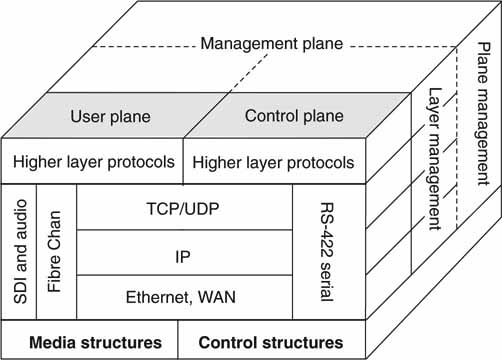
• Data or user layer—A/V data moving across links in RT or NRT. The data types may be all manner of audio, video, metadata, and general user data. This plane is alternatively called data or user. One term describes the data aspects of the plane, whereas the user handle denotes the applications-related aspects.
• Control layer—This is the control aspect of a video system and may include automation protocols for devices (A/V clients, VTRs, data servers, etc.), live status, configuration settings, and other control aspects.
• Management layer—Element management for alarms, warnings, status, diagnostics, self-test, parameter measurements, remote access, and other functions.
This model has been used for years in the telecom’s world with mature stacks across all three domains. In this case, the data plane is the actual data/protocols related to a telephone conversation, the control plane is the logic/protocols needed to establish and manage a call, and the management plane manages switching systems and configures them for subscriber-calling features. The famous Signaling System (SS7) protocol is used worldwide as the control protocol. SS7 is an architecture for performing out-of-band signaling in support of the call-establishment, billing, routing, and information-exchange functions of the Public Switched Telephone Network (PSTN). The legacy of the telecom’s logical view of the three planes is being applied to IT systems and hence AV/IT systems. Of course, the three stacks are completely different for our needs, but the overall concepts are still valid.
The detailed examination of the three layers and their implications is left to Chapter 7.
2.6 INTEROPERABILITY DOMAINS
Interoperability is mandatory for creating practical media workflows. This section outlines seven chief domains that contribute to interoperability between an A/V system and external points. The seven numbered interop domains are shown in Figure 2.18. For sure, there other domains, but these seven are frequently encountered. Domains 1 and 2, 3, and 4 comprise the data/user, control, and management planes, respectively, as outlined in Figure 2.17. Domains 5, 6, and 7 divide up the stack of a storage system, a user/data plane.
FIGURE 2.18 Seven key interoperability domains.
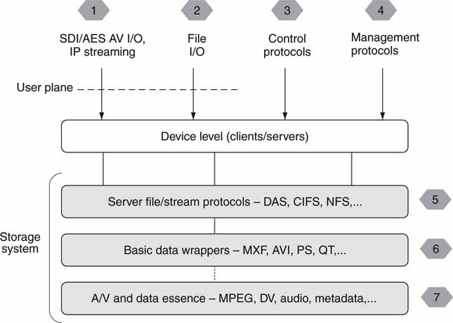
Frankly, older non-AV/IT systems had more interoperable functionality because there were fewer data formats, control protocols, and interfaces. There was a time when a video system could be built using one VTR control protocol and links for composite video (SD only) and analog audio. Today there is more of everything—more formats, more interfaces, and more protocols—so the move to AV/IT provides more choice with the associated headaches of more chance of interoperability problems between vendors’ gear. To be fair, even without the IT component, advanced A/V interfaces and data structures are more complex than those from just a few years ago.
Think of Figure 2.18 as representing a simple A/V system with combinations of I/O, control ports, management ports, and storage access. Viewing all seven together provides a higher-level view of how to realize cross-product interoperability across a range of system components.
2.6.1 Domains 1 and 2: Streaming and File Transfer Interfaces
Domains 1 and 2 have several dimensions, including file and streaming protocols and file formats. FTP has become de facto for file transfer, but there are other choices, as Table 2.4 outlines. However, file incompatibility can be a cause of grief.
Streaming using IT means (LAN/WAN) is not well established for professional A/V systems, despite its common use in the Web space. Oh sure, IP streaming is used for low-bit rate proxy browsing, but high data rate, IP-based streaming is not common except for some A/V trunking applications. …
Traditional A/V streaming interfaces such as SDI, composite, ASI, AES/EBU audio, and so on are well documented and supported by most equipment. If a vendor supports one of these interfaces, there is little that can go wrong. This interface point is likely in the first place in terms of interoperability and maturity. In the context of the three planes, this is a data plane element.
2.6.2 Domain 3: Control Interface
The control interface is vital for automated operations. Some, but not all, elements have a control interface point. For now, let us postpone a discussion of domain 3 until Chapter 7.
2.6.3 Domain 4: Management Interface
Management interfaces are required for monitoring device health, for diagnostics, and configurations. This interface is discussed in detail in .
2.6.4 Domain 5: Storage Subsystem Interface
Clients can connect to storage using several mature protocols. There are two classes of storage interfaces:
• DAS (direct attached storage) using SCSI, Fibre Channel, USB2, IEEE 1394, or other interfaces
• Networked-attached clients using SAN and NAS technologies
If you have ever connected a disk array to a PC or server, you have implemented DAS. When a client is outfitted with a Fibre Channel I/O card and connects to a common storage array, a SAN is being implemented. Whenever a client accesses stored files on a networked file server, NAS protocols are being put to work. NAS is a client/server file-level access protocol that provides transparent networked file access. NAS-connected clients are more common than SAN-connected clients due to the popularity of high-bandwidth file servers and Ethernet/IP networking.
Chapter 3B is dedicated to the coverage of DAS, SAN, and NAS. The bottom line is this: for client interoperable connectivity to storage, standards should be used. Always ask your providing vendor what protocols it uses for client-to-storage connectivity.
2.6.5 Domains 6 and 7: Wrappers and Essence Formats
The next pieces in the interop puzzle are the file wrapper and essence formats. A wrapper format (interface 6) is not the same as a compression format. A wrapper is often a content-neutral format that carries various lower-level A/V data structures. The simplest wrapper may only provide for multiplexing of A V. The ubiquitous AVI file type is a wrapper and can carry MPEG, DV, Motion-JPEG, audio, and other formats. These are often called A/V essence formats (interface 7). Another wrapper format is MXF. This is a professional wrapper format standardized by SMPTE (377M and others) and has profiles for carrying many different video, audio, and metadata formats. Interface point 6 exists only if the stored files are wrapped by AVI, MXF, QT, or similar.
Also at layer 7 are metadata. Often, metadata are packaged within XML but not exclusively. There are currently several SMPTE efforts to standardize metadata for a variety of A/V system operational needs. Other general data are stored at this level too.
File format translation between external types and internal formats may be required. For example, an external AVI file may enter (or exit) a system, but the internal format supports only MXF. So the format converter remaps the A/V formats as needed. Several companies offer file conversion gateways, among which are Telestream’s FlipFactory, Digital Rapids’ Transcode Manager, Rhozet’s Carbon Coder, AnyStream’s Agility Platform, products from Masstech, and others. Despite having some new format standards for file exchange, such as MXF, there are boatloads of older formats that cannot be ignored. File conversion has some trade-offs, such as speed of conversion, potential loss of A/V quality, testing of format conversions, and proper handling of metadata. Chapter 7 covers format conversion in more detail.
2.6.6 Interop Conclusions
The seven interface points are crucial in achieving interoperability with external users and interfaces. Successful interfacing is founded on standards and commonly used protocols and formats. For sure, there are other interface points such as vendor-supplied APIs, but these seven form the core for most A/V systems. In complex systems there will likely be some interface incompatibility, but these issues can be managed. For the most part, SMPTE, the IETF, and ITU/ISO/IEC are the organizations responsible for standardizing data, control, and management planes.
2.7 TRICKS FOR MAKING IT ELEMENTS WORK IN REAL TIME
For many years, purpose-built gear was needed to acquire, move, process, and output A/V signals. When some early adopter equipment companies decided to use a mix of A/V and IT elements, there were objections from many quarters. Following are some classic objections to using IT components:
• They are not designed to pass frame-accurate RT video and audio.
• There will be too much packet loss, jitter, and delay.
• Ethernet is asynchronous and SDI is isochronous, so the two cannot interoperate.
• Available data rate is not well defined in an IT network.
• Building frame-accurate systems is impossible.
Then, too, there are objections about security threats such as viruses, worms, spyware, and other network-related pests. Security-related issues are covered in Chapter 8. But what about these other objections? Let us find out.
Figure 2.19 serves as the landscape for the basis of our discussion. The configuration shows NAS-attached clients, an Ethernet IP switch, and a file server (NAS storage). The clients access storage using the TCP/IP protocol suite. There are several areas where latency, jitter, and loss can accumulate if not managed properly. The trick to realizing excellent client performance is in the judicious use of the I/O buffer. Each client has a small buffer of a few seconds and they may be described as follows:
FIGURE 2.19 Making IT components work in real time.
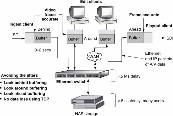
• Look ahead buffer as used in the ingest client.
• Look around buffer as used in the NLE client.
• Look behind buffer as used in the playout client.
Buffering is a way to smooth out IT component I/O irregularities. Of course, buffering also adds delay, and at times this may induce workflow problems or cause a client to appear as sluggish in response to a command. Generally, the more buffering that is used, the more irregularities and network problems may be hidden. So, in a way, more buffering solves everything (related to data jitter smoothing), yet time delay is evil (related to response times). So, indeed, the careful use of buffering can balance the needs of response time and smoothing needs. Hence, the art of buffering.
The general idea of buffering to smooth out irregularities is seen in Figure 2.20. A bucket is filled with an irregular flow of water. The input flow has an average rate that is constant, but the instantaneous rate will vary. A valve is adjusted randomly to represent irregular filling from uneven data delivery mechanisms inherent in the network switching, routing, lost packet recovery, storage delivery latency, and so forth. At times the bucket is nearly full, at other times nearly empty, but it never overflows or underflows. A regulator at the base of the bucket adjusts the output flow to be exactly even with no variations of flow rate regardless of the level of water in the bucket. As a result, the bucket acts like a buffer to smooth out any input irregularities and allows for a smooth output flow. The average input flow must equal the output flow for the method to work. When the source type of liquid changes, the bucket will need to be purged so as not to mix two dissimilar liquid types.
FIGURE 2.20 Using a buffer to smooth out irregularities.
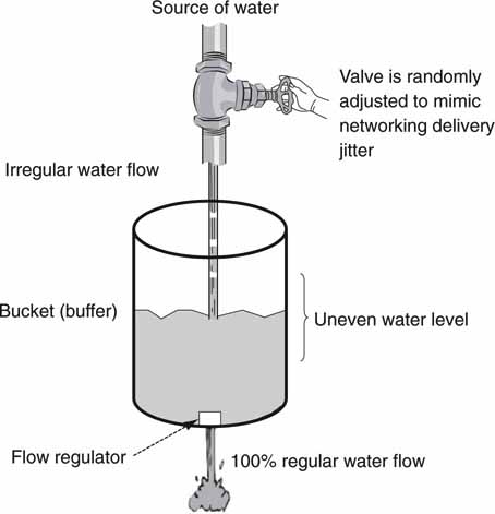
Using the bucket analogy, let us apply it to Figure 2.19.
The look behind buffer in the ingest client receives a regular flow of streaming A/V and sends it to storage over the network. The buffer has video stored from the past—hence, the look behind name. With a second or so of buffering, most IT-caused irregularities can be smoothed out as data are written to the storage. There may be occasions when a much bigger buffer is needed. Consider the case in which the storage array is offline for minutes longer. Under this condition, the ingest client can cache long periods of incoming video and write it to storage when the storage connectivity resumes. See the section on caching in Chapter 3B.
The look around buffer in the NLE client smooths out I/O requests to storage. This buffer lets a user look around (jog, shuttle) a point in the time line with a human-fast response. Again, using bigger buffers (caching) yields even more advantages.
Finally, there is the look ahead buffer. This one is located in the playout client and queues A/V data for frame-accurate playout. In many video applications, there is ample time to queue a file into the buffer space before playout starts. However, output buffers may need to be “burst filled or charged” at up to 5 × RT rates to accommodate immediate requests for A/V playout. The burst filling burdens the infrastructure with much higher data rates but usually for less than 1 second. The design quandary is to support large surges of buffer charging yet not saddle the system with a commensurate cost increase due to increased peak rates.
The system in Figure 2.19 has a limitation, however. The minimum “in to out” delay can be large, on the order of several seconds. There is recording latency due to input buffering, playout latency due to the output buffer, and storage array access latency. When the storage is Flash memory based, the in/out minimum delay may be less than a second. In the final analysis, buffering is the magic needed to coerce an IT infrastructure to behave in an A/V-civilized manner.
2.8 USING IT METHODS TO ROUTE TRADITIONAL A/V SIGNALS
One of most common operations in a facility is to route streamed A/V signals. Figure 2.21 illustrates a traditional A/V routing structure using SDI links. Three SDI routers switch the A/V signals. Two key features of this configuration are very small in/out latency (on the order of tens of nanoseconds), and H/V timing is easy to establish at any point in the chain. Another feature is easy splitting of a signal for more than one output. In this case, AV 1 is fed to two outputs, one for signal monitoring.
FIGURE 2.21 Traditional A/V router example.
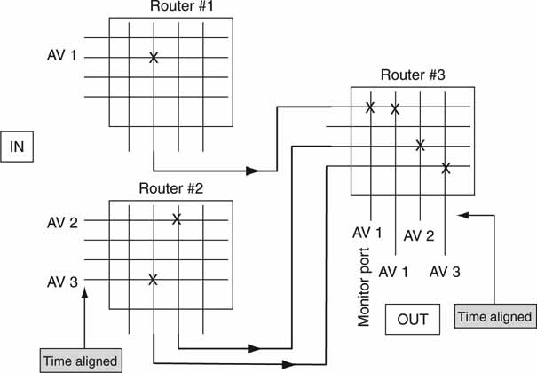
What is the IT-based counterpart? Figure 2.22 shows an example. Ideally, the in-to-out relationships should be the same as in Figure 2.21. The router layer may be IP switching or other non-video-specific means. Today there are no IT-based routing means to duplicate the configuration specs found in Figure 2.21. Why not? The following summarizes the issues:
FIGURE 2.22 Using IT-based routing to transport A/V signals.
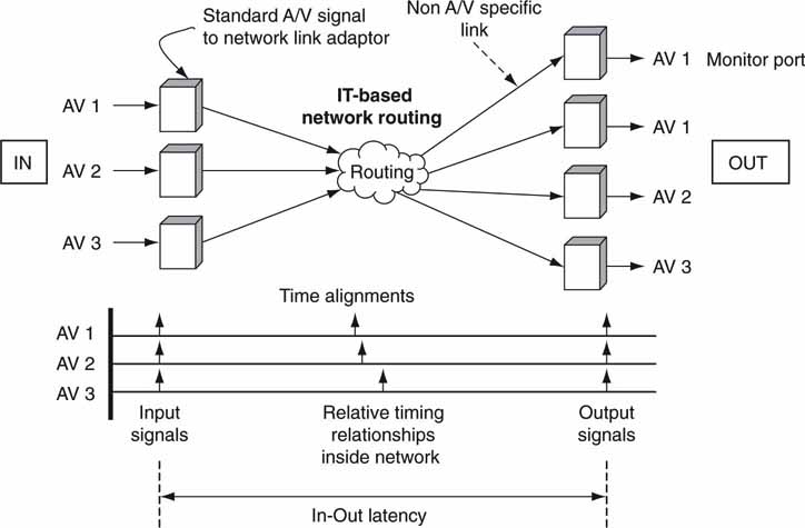
• IP networks have latency on the order of tens of microseconds to many milliseconds for campus size routes.
• H/V timing is lost during network routing. H/V timing must be re-established at the output ports. Protocols such as RTP support time-stamped streaming over IP networks, but even this does not guarantee recovery of the input H/V timing.
• Point to multipoint (splitting an input signal into one or more outputs) is difficult to achieve. IP multicast supports this but is not commonly used within an A/V facility.
The reality is that traditional A/V routing is a marvel and will not be replaced soon by IT means for those applications that demand it.
Duplicating the features of SDI routing is not easy, but over time methods will be developed as IT pushes deeper into all aspects of A/V. The concept of converting SDI signals to go over a WAN was mentioned earlier in this chapter, but this is normally for point-to-point video trunking and is an extender of SDI and not a replacement for it.
Importantly, the culture of using SDI and AES/EBU for all linking misses opportunities to use alternate non-real-time means such as file transfer. As a result, IT-based networking will replace timed A/V networks where it makes economic sense coupled with workflow efficiencies.
2.9 IT’S A WRAP: A FEW FINAL WORDS
This chapter outlined the essential elements of an AV/IT system. It is the basis of the remaining chapters in this book. Despite the fast-changing world of IT technology and products, the ideas in this chapter will not soon become stale with age. The comparisons between file transfer, streaming, and direct to storage are time-honored methods that will transcend any particular vendor’s products. The interoperability domains will only become more mature as industry experience accumulates. In the end, the information in these sections is a good foundation for understanding the essentials of networked media systems.
1 See Appendix F for more information on WANs.
2 For an excellent table summary of professional digital tape and compression standards, visit www.smpte.org/smpte_store/standards.
3 These values are point-in-time averages, so your mileage will vary.
REFERENCES
Britton, C. (2000). IT Architectures and Middleware: Addison-Wesley.
Devlin, B., et al. (2003). Nuggets and MXF—Making the Networked Studio a Reality. IBC 2003 Technical Conference Proceedings, 94.
Kovalick, A. (August 1998). A Reference Architecture for Digital A/V. SMPTE Journal.
Morelos-Zaragoza, R. H. (1991). The Art of Error Correcting Coding. Hoboken, NJ: Wiley & Sons 07030.