CHAPTER 4
Software Technology for A/V Systems
CONTENTS
4.1 User Application Requirements
4.2 Software Architectures—The Four Types
4.2.3 Architectural Comparisons
4.3.1 Database Connectivity Protocols
4.7 High-Performance Real-Time Systems
4.7.1 Achieving Real-Time OS Performance
4.7.2 Multimedia Extensions and Graphics Processors
4.7.3 64-Bit Architectures and Beyond
4.8 Software Maintenance and System Evolution
4.9 It’s a Wrap—A Few Final Words
4.0 INTRODUCTION
Only a few years ago A/V devices were hardware centric with little software value. Video product engineers were experts in real-time, frame accurate, circuit, and system design. Today the roles have reversed, with software being the center of functional value for most devices. Software, coupled with sufficient CPU power, can perform almost any A/V operation in real time. Thanks to Moore’s law, A/V-specific hardware is being relegated to I/O, live event switching, some real-time 2D/3D effects, and signal processing. Standard definition MPEG encoding and SD/HD decoding are done easily with a common CPU. HD MPEG2 encoding, especially MPEG4 Part 10 (H.264), still requires hardware support. When we look down the road, hardware A/V processing will become a rare commodity and software will rule. One important trend is to use the graphics processing unit (GPU, common in all PCs) to do real-time 2D/3D effects.
Figure 4.1 illustrates the software-centric nature of A/V systems. Of course, not every element has A/V I/O, but this only increases the saturation of software in the overall system. This chapter provides a working knowledge of the salient aspects of software as a system element. This includes
FIGURE 4.1 The software-centric AV/IT client.
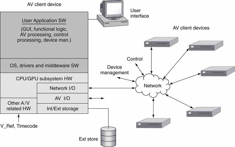
• User application requirements
• Software architectural models—four main types
• Software implementation frameworks—.NET, Java EE 5, Web services
• Real-time systems
• SW maintenance and system evolution
Performance wise, one might think that Moore’s law would always help speed up application execution. But due to software complexity and bloat, Wirth’s Law comes into play (http://en.wikipedia.org/wiki/Wirth's_Law). It states that software is decelerating faster than hardware is accelerating. Of course, this is not always true, but the law does have a profound effect for many applications. In jest, it has been said that “Intel giveth while Microsoft taketh away.”
This chapter does not provide specific coverage of programming languages or practices, although we do touch on these subjects along the way. Let us get started.
4.1 USER APPLICATION REQUIREMENTS
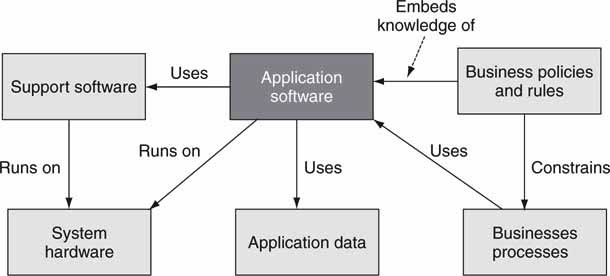
Software user applications come in a variety of shapes and sizes. The two main user application types are server based and client based. Software “services” are used by applications but are not usually complete applications. Service concepts are covered later in this chapter. Figure 4.2 illustrates a context diagram for user application software. This high-level example shows the action verbs associated with an application. Context diagrams illuminate how a software component integrates into the bigger picture. When you are completing an application design, a context diagram is useful to locate missing or duplicate relationships.
FIGURE 4.2 Context diagram for application software.
The core application features and issues are as follows:
• Functionality—Does it meet your operational and business needs?
• GUI look and feel—How does the interface behave?
• Ease of use—Are operations intuitive? Training needed?
• Performance—Are benchmarks available to compare vendors’ products?
• Quality of result—Does the A/V output quality meet business needs?
• Standards—Does it conform where applicable?
• Reliability—Is it stable when pushed to limits?
• Network friendliness—How well does it perform during network anomalies? Is there a readily available pool of trained users?
When evaluating a product, consider these minimal aspects of design. Some of the features are best evaluated by the technical staff and others by end users. Since the GUI is ever present, let us focus on six principles for good design, as outlined in Table 4.1.
Table 4.1 User Interface Design Principles
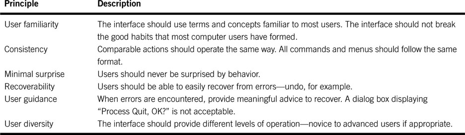
Some well-meaning interface designers try to be too clever and break the first rule, believing that new user paradigms are a good idea. True, there is room for innovation, but designers should leverage users’ good habits when possible. Some applications are self-contained and do not depend on any networked resources, e.g., using a word processor on a PC. More and more, however, applications rely on available services across a network. The end goal is a great application that users find compelling from all angles. What software architectures are available to reach this goal? The next section reviews the four main types in common usage.
4.2 SOFTWARE ARCHITECTURES1—THE FOUR TYPES
At some point when users are discussing software, religion usually enters the picture. For sure, there are priests and disciples of programming methods and languages, operating systems, and architectures. In a non-denominational sense, this section reviews the central methods for solution construction using software.
What is a software architecture? Whether it is the humble microwave oven’s embedded processor or Google’s 500K searching servers, their software is constructed using a topology to best match the functional objectives. If done poorly, it is a pile of spaghetti code; if done well, it is more like an awardwinning building or well-thought-out city plan.
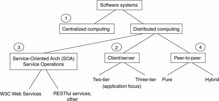
The city plan is a useful analogy. For example, central Paris is constructed as a star centered on the Arc de Triomphe, whereas Manhattan is grid based. These are high-level plans and do not normally constrain how individual buildings look and feel. From this perspective, let us examine four different “city plan” architectures without detailed concern for the individual buildings. Figure 4.3 shows the taxonomy of the four plans under discussion. For sure, there are other ways to divide the pie. This illustration is not meant to be a rigid definition, but merely one way to segment the architectures under discussion. The first to be considered is the centralized architecture.
FIGURE 4.3 Software system’s taxonomy.
4.2.1 Centralized Computing
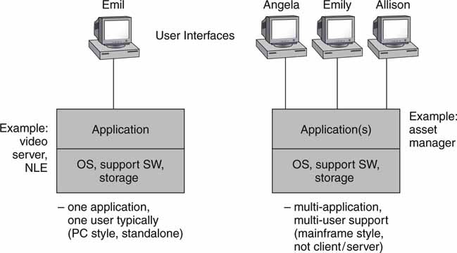
Centralized computing is a monolithic system ranging from a basic computer with a user interface (the ubiquitous standalone PC) to a mainframe computer system with hundreds of simultaneous users running multiple applications. This is the most basic plan and has been in use since the days of ENIAC, the world’s first electronic, programmable computer. It filled an entire room, weighed 30 tons, and consumed 200 kW of power when commissioned in 1945 (ENIAC). Oh, the joy of Moore’s law.
Many A/V devices are monolithic in nature. The standalone video clip server, character generator, PC-based edit station, and audio workstation are all examples. Most of these are single-user applications. Older mainframe systems never found a niche in A/V applications and are less popular with the advent of client/server methods. Large, centralized systems can suffer from scalability and single-point-of-failure reliability problems. See Figure 4.4 for a view of these two types of design. Importantly, IBM, which pioneered OS virtualization for mainframes, has breathed new life into the machines. It is common to run 200 virtual Linux servers under one mainframe (System z) for large enterprise applications.
FIGURE 4.4 Single and multiuser centralized systems.
Moving on, another class of system is distributed computing. This main class is divided into three smaller classes. The following sections review these methods.
4.2.2 Distributed Computing
In the distributed computing category, there are three main classes (marked 2, 3, and 4 in Figure 4.3). All share the common attribute of using networking and distributed elements that, when combined, create a solution. The three classes are as follows:
1. Client/Server2 (application focused)
a. Two-tier C/S (flat)
b. Three-tier C/S (hierarchical)
2. Service-Oriented Architecture (SOA) (service operations)
a. W3C Web services
b. RESTful Web services, other
3. Peer-to-Peer
a. Pure
b. Hybrid
Let us review each of them.
4.2.2.1 The Client/Server Class
The Web as we know it rests on the bedrock of the client/server architecture. The client in this case is a Web browser, and the server is a Web server accessed via an address such as http://www.smpte.org. The C/S model is found in all aspects of modern software design, not just Web-related systems. There are three layers to a client/server dialog: presentation, application, and data. These layers are glued together using various middleware connectivity protocols. Figure 4.5 (top) shows middleware as a connector that links the various layers as needed. Middleware is discussed in more detail in Section 4.3. Figure 4.5 (bottom) shows three different but common C/S configurations.
FIGURE 4.5 Middleware and layering options.
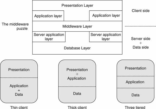
• Thin client: The presentation layer is on the client, and the application logic and data are on the server. An example of this is a terminal with a simple Web browser connecting to a Web server. The client is called “thin” because it hosts only the browser and not the application or data functions. This is a two-tier model.
• Thick client: Both the presentation and application logic are on the client, hence its thickness. An example of this is a sales report (spreadsheet) where data cells are filled in from a remote database. This is a two-tier model.
• Three tiered: In this case, the client supports the presentation, the server supports the application logic, and the database is the third layer. Examples of this configuration abound, and many Web servers are based on this model. The client is thin in this model.
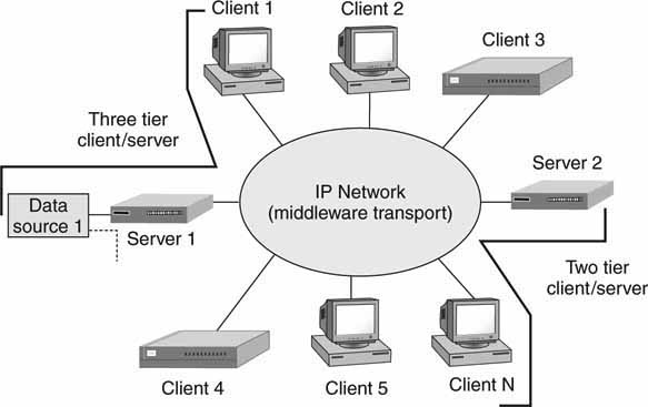
Figure 4.6 illustrates examples of two- and three-tier models in a networked configuration.
FIGURE 4.6 Client/server in a two- and three-tier architecture.
As the naming implies, clients and servers are separate entities that work together over a network to perform a task(s). An exact definition of client/server is cumbersome, so let us define the term by its characteristics. The following definitions were loosely paraphrased from (Orfali):
• Server: The server process is a provider of services, and the client process is a consumer of services. The C/S method is a clean separation of function based on the idea of a service. The service may be a complete application (Web server, file server, email server, etc.). A service may also perform a simple function, such as a file converter or a currency value converter.
• Asymmetrical: There is a many-to-one relationship between clients and servers. Clients initiate a dialog by requesting a service. Servers respond to requests and provide a service. For example, one Web server can provide Web pages to thousands of simultaneous clients.
• Transparency of location: The server may be anywhere on the network or even within the client platform. The client has no knowledge of the server’s location. Client interfacing hides the connectivity to the server. In reality, servers that are distant from the client will offer a large response time if the network QoS is poor.
• Mix and match: The client and server platforms may be heterogeneous and allow for any combination of OS and programming languages on either side. This is why a PC or Mac Web browser can access the same Linux-based Web server without interoperability problems (ideally). This is a key feature and allows programmers to choose the client/server OS and programming language that best suits their needs.
• Scalability: C/S systems can be scaled horizontally or vertically.
• Horizontal scaling is adding/removing clients with little or no performance impact. Vertical scaling adds servers to meet loading and performance requirements.
These client/server characteristics permit systems to be built with distributed intelligence across a network. Clients may have human interfaces. As a result, there is no reason to be dogmatic in our definition of the C/S configurations, but rather embrace the openness and flexibility of the concepts.
Take another peek at Figure 4.6. The two- and three-tier nature of C/S is illustrated. The notion of three tiers adds a database layer. Instead of the database being integrated into the server, it becomes a separate element that may be shared by many servers. When the data storage aspects are separated from the service aspects, it is easier to scale and manage large systems. Hierarchical systems provide for scalability and data separation at the cost of complexity. Specialized versions of C/S are grid and cluster computing, which are discussed in Appendix C.
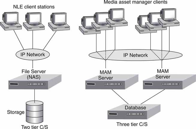
In the framework of A/V systems, the C/S configuration is quite popular. Figure 4.7 illustrates two examples. The two-tier NAS server example is discussed in Chapter 3A. With the three-tier model, media asset management (MAM) servers share a common database, which permits application server scaling independent of data. The three-tier model is a great way to scale a system. Of course, the networking QoS should support the C/S sustained data rates. Failover is not shown but could be included in the design. Next, let us look at a specialized version of C/S called the service-oriented architecture.
FIGURE 4.7 Sample A/V applications using client/server.
4.2.2.2 The Service-Oriented Architecture (SOA)
The sage Bob Dylan penned these lines (1963):
Don’t stand in the doorway
Don’t block the hall
For he that gets hurt will be the one who has stalled
—For the times they are a-changin
Dylan’s words are great advice to anyone who wants to constrain software to the comfort of application-focused client/server or standalone systems. These methods are quietly giving way to various forms of the service-oriented architecture (Figure 4.3, item 3).
Figure 4.8 shows one simplified landscape of a SOA. It starts from business principles. This is absolutely key to a true SOA implementation. From business needs, application principles are defined. Applications rely on technology (distributed software services, networking, servers, etc.) for implementation. Finally, the stack rests on data principles (values, formats, schemas, interfaces, metadata, etc.). A SOA is a powerful ally for creating business efficiencies for the media enterprise.
FIGURE 4.8 The SOA principles stack.
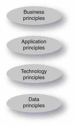
Consider an example of Figure 4.8 in operation. At the business level, there is a request to repurpose an archived program for the Web. This may include locating and viewing a proxy version, checking on usage rights and time windows, editing, transcoding, QA, and publishing. Appropriate applications are invoked, some automatically. These applications may be a mix of services (IP rights, auto-transcoding, and so on), a job request for some minor editing tweaks, and publishing to the Web. The entire stack is applied to meet the business need to publish media content. The more automated this process, the more cost effective and timely it will be. Incidentally, the lowest two layers may be time-aware for video frame accurate signal and control purposes. Video frame accuracy is a special need of the media enterprise.
SOA provides the discipline to create scalable, reliable, managed business workflows. Using the technology principles of service reuse, granularity, modularity, and interoperability, a SOA provides a firm infrastructure for efficient applications deployment. Agility (easy reconfiguration for change) and visibility (dashboards, key performance indicators—KPI, see glossary) are also major benefits of a SOA.
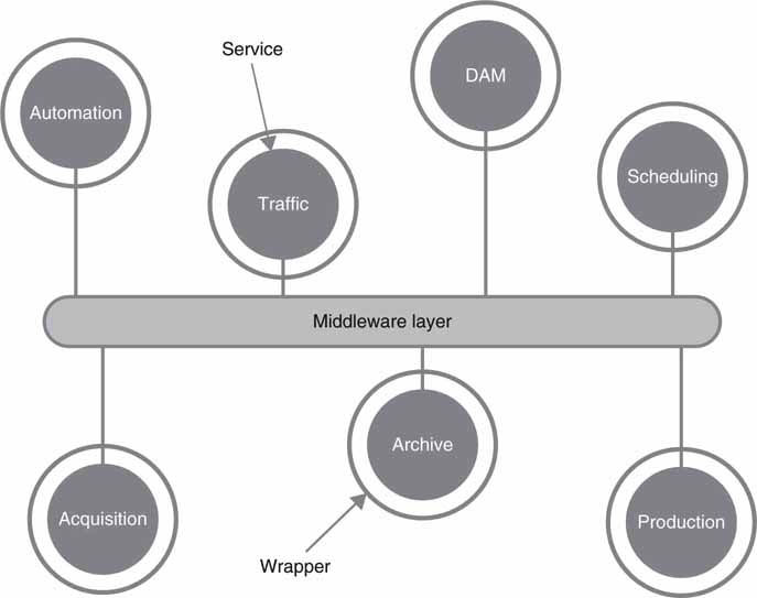
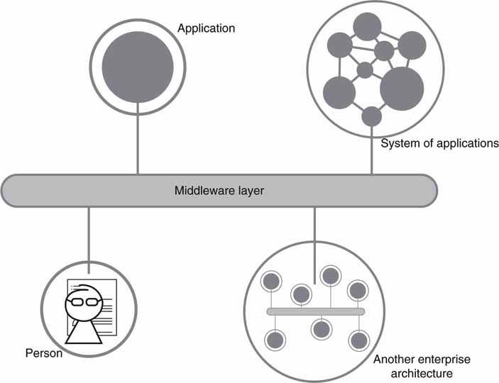
SOA is broadly defined as an architecture of loosely coupled, wrapped services communicating via published interfaces over a common middleware layer (Footen, Faust). First of all, this definition is not universal; there are others, but this will suit our needs and scope. This terse definition needs some explanation. The terms services, middleware, and wrappers will be explained. See Figure 4.9.
FIGURE 4.9 A SOA’s basic elements.
Source: (Footen, Faust).
Before these terms are examined, a few words of caution: there are no strict term definitions that all industry gurus agree on. Some may quibble with the precision or scope of a definition. Given that, let’s proceed.
Starting with services, the definition most often given is a loosely coupled component (software normally) capable of performing a task.3 As an example,
Amazon publishes its core system services (listings, searching, viewing products, etc.) so that its business logic can be used by external partners. Do a Web query for “Amazon Web services” to find examples. The services are defined by API interfaces. The services outlined in Figure 4.9 are generic examples and may be replaced with others ranging from simple transcoding to more sophisticated applications. Service technology is covered in the next section.
What is meant by loosely coupled? Basically, the service is independent, selfcontained, stateless (usually), and isolated such that implementation (C++, C#, Java, and so on) and location are hidden. So, changing a service’s location (moved from server A to server B) and implementation language should not affect how the service performs within the limits of its QoS spec.
Middleware is defined in Section 4.3.
Wrappers sit between a service and the middleware layer and transform messages that pass through them. Wrappers provide a layer of abstraction necessary to connect applications or tools not originally designed as services. Wrappers can mask the technical differences between components, making them uniformly interoperable in the SOA environment. Wrappers are used only when needed.
SOA in Context
Finally, SOA acceptance is growing in mid- to large-scale enterprise organizations. According to Randy Heffner of Forrester Research, at least 63 percent have implemented at least one SOA implementation by the end of 2008. So, looking forward, many media organizations will be using SOA principles. This impacts equipment design, since vendors will be providing service interfaces on their products to better interface into SOA environments. In the end, this creates more flexible workflows and efficient facilities.
Of course, there is much more to learn to fully appreciate SOA. Consider researching topics such as the Enterprise Service Bus (ESB), management tools (HP’s SOA Manager), frameworks (IBM WebSphere SOA), business process management methods (Business Process Management Initiative, BPMI. org), standards from OASIS (www.oasis-open.org), and the Advanced Media Workflow Association (www.AMWA.tv) for media-facility specific standards and best practices. Incidentally, this author is a board member of AMWA and contributes to document specifications for our industry. See, too, materials from the SOA Consortium for case studies (www.soa-consortium.org/case-study.htm).
Next, is a summary of the generic Web services model.
4.2.2.3 Web Services Model
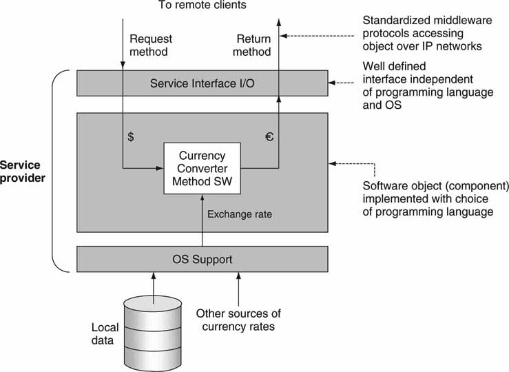
A service is a networkable component that provides well-defined functions (tasks) using a standardized data interface. An example is a service that converts currency from dollars to Euros. The input to the module is a dollar amount, the method is to convert to Euros using the current exchange rate data, and the returned value is in Euros. If the service is well defined, then any client can call on it for the conversion service. Importantly, the service may be called by a variety of unrelated user applications. It is not difficult to imagine a collection of individual services whose aggregated functional power is equivalent to, say, a standalone application server.
The term Web service is somewhat a misnomer and has generated no end of discussion. A service is not required to have a Web connection. This is a generic name and really implies network connectivity—Web based or otherwise.
Figure 4.10 shows a single service for converting dollars to Euros in a server environment. The component is invoked by some external client, and it returns the value in Euros based on the input value in dollars. Another example is a file metadata service; you provide a file name, and its structural metadata are returned—compression format, aspect ratio, bit rate, length, and so on. One of the more important aspects of service definition is its interface specification so that any heterogeneous client may use the service.
FIGURE 4.10 Example of a software service.
Some Insights into the Services Landscape
Not all services fall into the neat categories shown in Figure 4.9. Most often a SOA system will require services to span people (yes, people can offer SOA services), simple application services, connection to legacy applications, and to other large systems. Figure 4.11 shows a landscape of services spanning these domains.
FIGURE 4.11 A landscape of service connectivity.
Source: (Footen, Faust).
Unless a designer has a blank canvas to start with, the services will need to span across system components not always designed for services support. Often, business-critical information is scattered among islands of data and stored in different formats on incompatible systems. Adapters can create a bridge to provide a consistent middleware interface and data formats. Companies such as Pervasive Software (ww2.pervasive.com) provide service adapters for hundreds of legacy systems and cross-convert files, service interfaces, messages, applications, and database formats.
But what about the people interface? Today, work tasks may be assigned via emails, phone calls, and office memos. These methods are incompatible with SOA. A better way is to implement a to-do list as a network attached service with a UI. All tasks are formally documented and registered with this service application. Progress steps may be updated. When a task is complete, the “finished” button is hit—often to great satisfaction. Task progress and completeness contribute to business intelligence. If this new approach is not perceived as a positive business process, then users will bypass it and return to emails and phone calls.
In the previous section, you examined a content repurposing example. One of the process steps is to implement some creative editing tweaks. Ideally, this job should be recorded with a SOA-enabled task register. Then, once complete, the next step (QA review) can be automatically launched. The bottom line is a faster and more efficient workflow with good business intelligence visibility. For more information on the “people interface” for SOA, see, for example, BPEL4People at www.wikipedia.org/wiki/BPEL4People.
The service interface definition may take one of several forms. The two most popular are the W3C Web services model and the RESTful model. When experts compare these two service models, the discussions can quickly become a religious debate. They each have application spaces, and neither one is ideal for all use case scenarios. Next, let’s look at each one.
4.2.2.4 The W3C Web Services Model
The World Wide Web Consortium has defined a version of Web services that is in wide usage. See (Erl), (Barry), (Graham), and www.w3.org/2002/ws. The W3C specification defines the interfaces and middleware but is silent about OS, programming language, and CPU choices. W3C methods fill out many of the details left open in the generic view of Figure 4.9. Designers have great latitude in how they implement services using tools defined by the W3C. This model has had wide acceptance in enterprise SOA applications development.
Web services4 have the following characteristics:
• Self-describing: Web services have a well-defined interface.
• Published, found, and invoked over a network: A network is the communication media that Web services participants—requestors, brokers, and providers—use to send messages.
• Platform and language independent: web services can be implemented on different platforms with a variety of programming languages.
Both Internet client/server and Web services use IP networking as a transport mechanism, but their purpose and implementation are different. Traditional Web servers return HTML text/graphics that are displayed in a browser. Web services, however, return XML messages/data to a client process that subsequently uses the information. For the most part, Internet client/server applications are process-to-human centric, whereas Web services are process-to-process centric.
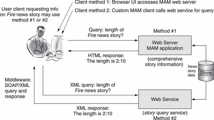
Figure 4.12 shows two methods by which a client queries for the length of a news story. In the first case, the client uses the PC browser and accesses a Web server (with media asset management functionality) that provides the query/response operation. The client/server transaction is HTML/HTTP based. This is an example of a “thin client,” as shown in Figure 4.5. In the second scenario, the client runs a local MAM application installed on the PC. This application calls upon the Web services query/response operator when needed. The MAM client application formats the response for display. This is an example of the “thick client” shown in Figure 4.5. The Web service query/response interface is defined using a SOAP/XML methodology. Each of these two methods has tradeoffs in terms of performance and user look-and-feel.
FIGURE 4.12 Browser-based and Web services application examples.
SOAP AND XML: THE CLEAN WAY TO COMMUNICATE 
Pass the SOAP and XML, please. SOAP has floated to the top as a preferred way to transport XML messaging. XML is widely used for packaging messaging and data elements. SOAP/XML forms the foundation layer of the Web services stack, providing a basic process-to-process messaging framework that other layers can build on.
Under the Hood of Web Services
Web services may be advertised so that others can use them. For example, the “story query service” in Figure 4.12 can publish its service methods to a registry. Applications can then find the story query service and use it. Figure 4.13 shows the three players in the Web services dance: the service provider, the service consumer, and the service broker (a directory or registry). The dance goes like this:
1. The service provider registers its methods with the service broker. The broker knows the location and methods of every registered service.
2. Service consumers (clients) inquire of the broker to locate a service.
3. The broker returns the service address and methods.
4. Clients may then use the service as needed (transactions 4 and 5 in Figure 4.13).
FIGURE 4.13 W3C’s Web services communication model.
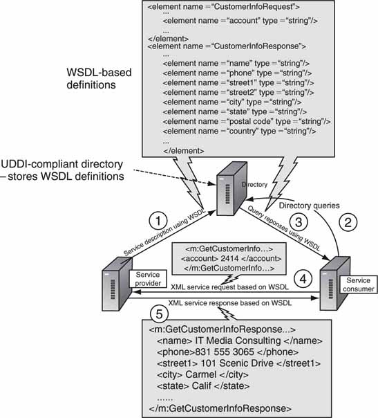
The key tools in Figure 4.13 are SOAP, XML, WSDL, and UDDI. SOAP and XML are explored in Section 4.3. The Web Services Description Language (WSDL), expressed in XML, defines the methods and data structures employed by a service. It offers the first standard way for clients to know exactly what methods a service can perform. Consumers parse a WSDL document to determine the operations a Web service provides and how to execute them. UDDI is the Universal Description, Discovery, and Integration protocol. A service provider registers its service functionality, expressed in WSDL, with the directory using UDDI. The discovery broker in Figure 4.13 supports both UDDI as a registering mechanism and WSDL as a service descriptor. Web services can exist without UDDI, but the services must be advertised by other means. A study of Figure 4.13 shows the common use of XML/WSDL for message exchange.
The Web services concept holds great promise for A/V environments. There are many workflows used daily in TV stations, post-houses, and other A/V facilities worldwide that can benefit. Imagine a collection of Web services for logging, cataloging, querying, archiving, controlling, scheduling, notifying, transferring, converting, testing, analyzing, and so on. Vendors can develop a cache of these services and use them to create turnkey solutions based on customer need or a competent A/V facility staff programmer can assemble these services to perform useful applications. This may not be practical for small facilities but may be for larger ones. The possibilities are endless. Of course, the real-time capabilities of Web services depend on the QoS of the service definition.
Despite the promise of UDDI, it has not gained wide acceptance by industry or for the open Web. Its goal of a universal place to find services has remained a dream. On the surface, UDDI seems a great idea that providers would flock to. In reality, other methods have replaced it for the most part. In the enterprise, private service libraries have become the norm. An overseer of services maintains a list of WSDL services for all programmers to access.
For the general Web, a global index has never found a home either. Who would own it and maintain it? What is the business model behind it? Who will vouch for a service’s reliability and security? Services for the public Web are largely offered by Amazon, Google, Microsoft, Yahoo!, and others. In addition, these services are not exclusively WSDL based, so UDDI would offer, at best, a partial registry. The UDDI is not dead, and time will tell if it will find wider acceptance.
To promote best practices for service developers, the Web Services Interoperability Organization (WS-I) has defined 25+ standards and recommendations (www.ws-i.org). Among the more notable ones are WS-Security, WS-Addressing, WS-Reliability, and WS-I Basic Profile. The abundance of documentation requires expert know-how to implement these. This is yet another reason to find expert guidance when starting a Web services-related project. Don’t let the volume of standards scare you. This indicates that the SOA industry is putting muscle behind the bat. Best practices will help filter and prioritize.
4.2.2.5 The RESTful Services Model
The main alternative to W3C’s Web services is the so-called RESTful services. REpresentational State Transfer (the REST part) is a key design idea that embraces a stateless client/server architecture in which the Web services are implemented by named Uniform Resource Identifiers (URIs). Rather than using SOAP carrying WSDL messages, REST relies on the simple paradigm of create, read, update, delete (CRUD services) per URI. We can think of a URI, in this context, as a “Web server address” that implements CRUD operations. See http://en.wikipedia.org/wiki/Representational_State_Transfer. RESTful services are useful in SOA and pure client/server environments.
Some of the defining principles of RESTful services are
• Client/server style.
• Stateless. This feature allows for simple implementation. Different servers can handle initial and future service requests—large-scale enabled.
• Cacheable and layered. This feature permits gateways, proxies to intersect traffic without requiring protocol translation—large-scale enabled.
• A constrained set of content types and well-defined operations (CRUD). XML documents are frequently used as data structures.
RESTful services rely on HTTP—the ubiquitous protocol for accessing Web pages from a server. HTTP supports the four CRUD operations as follows:
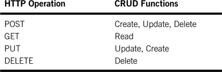
Let’s consider an example of a weather service. The URI processes weather requests. Each city name has a URI resource associated with it in the form: http://weather.example/cityName:
• GET http://weather.example/city: Get the current weather at city. Simple XML document returned with weather data. Note that HTML data structures are not returned as with a typical Web page request.
• POST http://weather.example/city: Set weather information for city. Simple XML document input.
• DELETE http://weather.example/city: Delete a city from the system.
• POST http://weather.example/add/city: Add a city to the system.
Note that the GET function does not modify the services’ data structures. However, POST and DELETE modify, so these services need a special authentication step not described here. A garden variety Web server can implement the weather service.
The raw simplicity and worldwide scale of RESTful services have given them a huge boost in usage compared to SOAP/WSDL methods in non-enterprise applications. Amazon, Google, Microsoft, Yahoo!, and many others offer public RESTful services for all sorts of purposes. See http://code.google.com/apis/maps or http://aws.amazon.com for more examples.
It’s easy to imagine a collection of media-related URIs for processing A/V data and metadata. For a representative example of video-related REST services, see Veoh’s developer site (www.veoh.com/restApiDoc/restReference.html).
So, Web services will be divided among SOAP/WSDL and RESTful methods although less common methods do exist. A decision to use one or the other will depend on many factors: scale, development tools, staff knowledge, existing infrastructure, public/private, standards, interop, reliability, cost, and more.
Next, let’s consider item 4 in Figure 4.3.
CLOUD COMPUTING AND SAAS
IBM president Thomas J. Watson (1952–1971) is known for his alleged 1943 statement: “I think there is a world market for maybe five computers.” However, there is no evidence he ever said this. Assuming the quote is valid, Mr. Watson was in error by four computers; he should have said one. Why? Applications and services that commonly run on a desktop operating system are now running in the cloud: the unbounded, ever-changing, elusive collection of millions of servers that make up the Web.
Okay, it’s not really one computer, but it appears to be so from the perspective of users of the network. Visit Google Maps or MySpace—most of Web 2.0—and you’re using cloudware. For enterprise use, Software as a Service (SaaS) is a business model for leasing network available applications. See Appendix C for more information on “cloud-everything.”
4.2.2.6 Peer-to-Peer Computing
The term P2P refers to a class of systems and applications that use distributed resources to perform functions in a decentralized way. P2P systems may be classed as outlined in Figure 4.14 (Milojicic). Layer two of the diagram shows the three main application domains. These are further segmented into eight specific application areas. No doubt, P2P has become a household name with the likes of Napster, Kazaa, BitTorrent, Gnutella, and other file-sharing programs. However, we should not paint P2P as evil; it has plenty of legitimate applications. Let us look at the three main domains for P2P.
FIGURE 4.14 P2P application classifications.
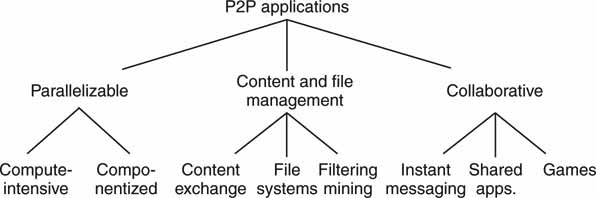
Source: HP Labs (Milojicic).
The first one is parallel systems. They split a large task into smaller pieces that execute in parallel over a number of independent peer nodes. The SETI@Home project has aggregated 1.8 million “client” computers to harness over 2 million years of equivalent computer time and counting. It is acknowledged by the Guinness World Records as the largest computation in history. True, this is an example of grid computing, but it uses P2P concepts. The second domain is that of content and file management and is mainly associated with file sharing, be it legal or illegal. Streaming, too, is supported by some applications. See Appendix I for a novel P2P streaming model. The third domain is P2P collaboration. Examples of this type are AOL and Yahoo!’s instant messenger (IM) and multiuser gaming (MUGs). Groove’s Virtual Office (www.groove.net) is a P2P application suite for sharing files, workspace, and other information. There has been little professional A/V use of P2P to date, although some facilities have used it on internal, protected networks for file exchange.
P2P Architectural Examples
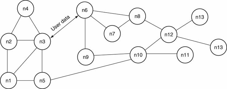
It is not difficult to imagine the topology of a pure P2P network (see Figure 4.15 for an example). Each node is a computer with one or more network connections to other nodes. Nodes interconnect using 1:1 communication for the purpose of data exchange. However, because any given node can support more than one P2P conversation, the diagram shows a general 1 :N connection space. In reality, the connections are networked and not hard-wired as the diagram may imply. There is no notion of a server or other hierarchy. This is true anarchy and one reason why it is virtually impossible to control and manage traffic between peers on the open Web. The Gnutella method relies on pure P2P, for example.
FIGURE 4.15 Pure P2P architecture.
Aside from the pure P2P model, there is the hybrid form, as shown in Figure 4.16. Anarchy gives way to hierarchy with the introduction of a directory server. The original Napster system, among others, used the idea of a main server to provide a list of files (or other information) and locations to clients. Once the client locates a file, the server connection is broken and a true P2P relationship takes over. The server makes file location a snap but is a bottleneck in what is otherwise an infinitely scalable architecture. Of course, the directory server can be replicated, but this leads to other issues. This model is good for private networks, and the server adds management features. The Kazaa model uses the idea of a super-node to act as a server. Some nodes are dedicated to act as servers and to communicate to other super-nodes to create a single virtual server.
FIGURE 4.16 Hybrid P2P architecture.
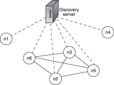
Concept: Microsoft.
Performance of P2P networks is problematic. Because of its decentralized nature, performance is influenced by three types of resources: processing power and its availability, storage, and networking. In particular, low delivery rates can be a significant limiting factor. Data sourcing client disconnect is a major issue when transferring large files. On the plus side, P2P can scale to millions of users with a combined computing power of trillions of operations per second. In fact, Ellacoya Networks, a deep packet inspection product company, believes that ~40 percent of all Web traffic is P2P related.
4.2.3 Architectural Comparisons
So, how does all this stack up? Which of the four architectural classes in Figure 4.3 has the edge? Well, the answer all depends on who the “user” is and what advantages and functionality are required. All four types find practical application use. Some key aspects of the four systems are as follows:
1. Centralized. Older, multiuser mainframe use is diminished greatly and defers to client/server methods. However, virtualization has given new life to this class. The single-user, ubiquitous standalone PC rules the client world. Most legacy A/V gear is standalone by design, such as VTRs, character generators, and NLEs. If connected to a network, the client becomes part of a C/S scenario in many cases. Dedicated devices such as A/V and IP routers are special cases of standalone systems.
2. Client/Server. It is the most powerful networked architecture in modern use. It is mature and offers advantages to users (inexpensive, accessible), application developers (tools galore, standards), and IT maintenance staff (management tools).
3. Service-Oriented Architectures. This space has been divided between two different Web service implementation frameworks and associated infrastructure methods. Its strengths are business process visibility, agility, scalability, aggregate reliability, manageability, and widely available development platforms and tools.
4. Peer to Peer. P2P is generally “out of control” in terms of IT’s management, QoS, and security needs. There are some exceptions to this, but for the most part, P2P is not popular in professional applications.
The distributed architectures (2, 3, and 4) rely on various forms of middleware to tie the pieces together. The following section reviews the essentials of middleware.
4.3 MIDDLEWARE CONNECTIVITY
Middleware is the layer of functionality that connects systems over networks for exchanging information between them or, put another way, is the “glue” that ties various distributed software layers together. Most middleware technologies are platform independent, but some are vendor specific.
Figure 4.17 demonstrates how middleware operates as a communication layer between client and server. In general, middleware is used in a variety of distributed computing architectures.
FIGURE 4.17 The role of middleware in a client/server transaction.
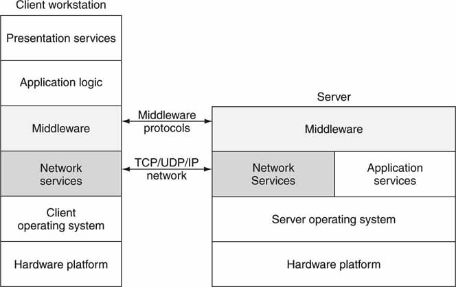
Figure 4.18 outlines a common scenario in which middleware ties the client(s) and server(s) together. For client/server interaction using middleware, the sequence of communication events is outlined in Figure 4.18 and later. The example illustrates a client calling a remote currency converter service. The sequence of events is as follows:
FIGURE 4.18 Process connectivity using middleware.
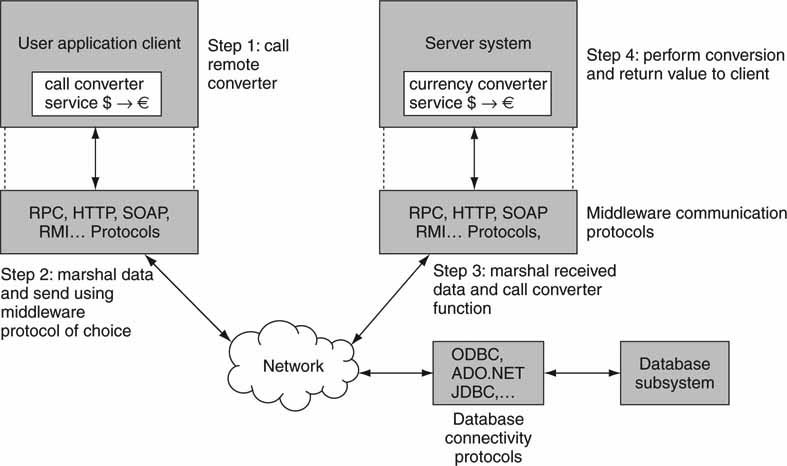
1. Client application formats user data structures and calls the currency converter service on the remote server.
2. Client middleware marshals the data into the select middleware format (RPC, RMI, HTTP/SOAP, etc.) and sends it over the network to the remote server. Importantly, the middleware data structures are independent of programming language (and OS) choices, which allows for true heterogeneous client/server communications.
3. The remote server receives the data structures and formats them for the target function (currency converter) in the local programming language.
4. The server application formats a response, marshals the data structures, and returns them to the client over the network. At this point a complete middleware transaction has occurred. In effect, steps 3, 2, 1 are repeated in reverse order to return the response to the client.
Ideally, a remote service across the network behaves as a locally called function. However, due to network delay and other network anomalies, this may not be so. There is generally no QoS defined for these protocols, so moving real-time A/V with them is problematic. They are best used for non-real-time operations: query, simple control, user interface, database access, application services, and “just in time” services such as format converters, transcoders, and so on. With sufficient care and time-aware services, frame accurate control of A/V I/O is possible.
The following middleware protocol standards are in widespread use:
• Remote Procedure Call (RPC). RPCs provide the means for one program to call the services (a procedure or other program) provided by a remote machine. The response is usually some data elements or status report. The RPC is the oldest protocol in this class. Millions of systems use the RPC library. See RFC 1831/1833 for more information.
• HyperText Transfer Protocol (HTTP). This is the primary communication protocol for connecting browser-based clients to servers over the Web. In a secondary sense, it is also used as a generic connector between a client, not necessarily browser based, and a server.
• Simple Object Access Protocol (SOAP). This is a basic means to move XML messaging between programs connected over a network. SOAP embeds XML data structures, and the package is transported using HTTP. Typically, a SOAP message (the request) is sent to a remote receiver, and it counters with another SOAP message (the response). XML is a good means for exchanging business-related information. See www.w3.org for more information on SOAP. The combination of SOAP/XML is the backbone of WSDL-based Web services.
• Remote Method Invocation (RMI). RMI is the basis of distributed object computing in a Java environment. It provides the tools necessary for one Java-based component to communicate with another Java component across a network. Think of this as a RPC for Java.
• .NET Remoting. This is a Microsoft concept for communicating between software objects in the .NET environment. .NET Remoting supports HTTP and SOAP (and other protocols) to transfer XML data structures between clients and servers, for example. This is roughly analogous to the RMI as used in a Java environment.
For SOA environments, the Enterprise Service Bus (ESB) is a special class of optional middleware. An ESB is software that sits between the services and enables reliable communication among them. See www.sonicsoftware.com for more insights on the ESB.
4.3.1 Database Connectivity Protocols
Another aspect of middleware is database connectivity (see Figure 4.18). What does this mean? For our discussion, this relates to heterogeneous clients or servers connecting to heterogeneous databases. In the context of media, a database may store metadata that describe A/V assets. Typical descriptors are title, length, owner/rights, trim points, format, descriptive key words, and so on. Edit stations, ingest control stations, browsers, traffic/programming, and device automation are among the types of clients that require database access.
The granddaddy of the database query is SQL. This is a language for accessing databases and doing adds/deletes and queries of the contents. By itself, SQL does not define how to connect to a database. Over the years several mature protocols have evolved to connect clients to databases. Highlighting the most significant, the following are in daily use:
• ODBC (Open Database Connectivity). This is an open standard defining how clients can connect to vendor-neutral databases. Microsoft defined it, but now it is an international standard and is used universally. Under the hood, ODBC uses SQL for operations on the database. Also, clients do not need to know where the database is located on a network or what brand of database is accessed. Of course, ODBC allows users to access vendor-specific features if needed.
• ADO.NET (ActiveX Data Objects). This is the cornerstone of Microsoft’s .NET framework for database access. This is an ODBC-compliant API that exposes the features of modern databases to client applications. It was designed for the .NET programming environment.
• JDBC (Java Database Connectivity). This provides database access to programs written in Java and JavaScript. It uses ODBC as the core of connectivity.
These database access methods are in wide use. For more information, see http://java.sun.com/products/jdbc for JDBC and www.microsoft.com for ADO.NET particulars. In the bigger picture, middleware is an adhesive to create a variety of architectures made of heterogeneous, programming language-neutral components.
4.4 IMPLEMENTATION FRAMEWORKS
This section reviews the programming frameworks and major languages used for implementing the architectures discussed in the previous sections. In particular, the focus is on client/server, SOA, and Web services models. The frameworks and platforms in common use are as follows:
• Microsoft’s .NET framework
• Sun Microsystems’ Java Enterprise Edition—Java EE 5 framework
.NET is Microsoft’s premier development platform and Web services software architecture. Sun Microsystems developed the Java EE for a similar purpose. Both of these are competing methods for developing client/server and SOA systems.
4.4.1 The .NET Framework
The .NET framework is an integral Windows component for building and running software applications. Figure 4.19 shows the main components in the .NET toolbox. The top level relates to Web server technology. Web servers are built with .NET’s Active Server Pages (ASP) and ActiveX Data Objects (ADO). The middle layer is the Visual Studio program development environment. This enables programmers to design, write, and debug software applications. The bottom layers support the W3C model for Web services. These three main divisions are mutually independent aspects of .NET.
FIGURE 4.19 The .NET working environment.
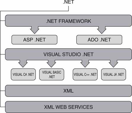
Concept: Microsoft
Key aspects of the .NET framework are:
• Supports over 20 different programming languages, mainly on X86 Intel/AMD CPUs. Visual C++, Visual Basic, and Visual C# are the most common.
• Works hand in hand with Microsoft’s operating systems.
• Manages much of the plumbing involved in developing software, enabling developers to focus on the core business logic code.
.NET has found a home with standalone as well as distributed systems. In fact, all the architectural classes in Figure 4.3 can be implemented using .NET’s tools, components, and connectivity. Many standalone A/V software applications use the .NET framework and development tools for program creation. Its tight integration with the Windows OS makes it the preferred framework for many software projects.
4.4.2 The Java EE Framework
The Java Enterprise Edition is a programming framework for developing and running distributed multitier applications. Defined by Sun Microsystems, it is a Java-based, modular service-oriented architecture methodology. Java EE is defined by method specifications and corresponding interface definitions for creating individual modules for an enterprise-level computing architecture. It supports Web server functionality and true W3C-based Web services connectivity.
In many ways, Java EE is similar to .NET: it supports distributed services, uses professional development platforms, and uses various middleware protocols for client/server communications. In fact, the .NET functionality stack in Figure 4.19 has equivalent layers in the JAVA EE world. One big difference is this: JAVA EE supports only the Java programming language. However, while .NET supporters brag about its multiple language support, Java supporters brag about its multiple OS support, including the popular open source Linux. In principle, .NET is write many (language choices) run once (only on CPUs with a Microsoft OS), whereas Java is write once (Java only) run many (choice of CPU and OS). The two camps have taken up arms over the virtues of each platform.
Figure 4.20 shows a simplified view of a hybrid JAVA EE environment: one browser based and the other Web services based. Browser-based clients (top right) interact directly with Java-based Web servers with Java Server Pages. This is a traditional client/server relationship in a Web environment. Non-browserbased clients (top left) interact with the Web services using W3C-defined or RESTful methods typically. The client executes local application code, which in turn calls the JAVA EE platform for services.
FIGURE 4.20 A simplified Java EE environment.
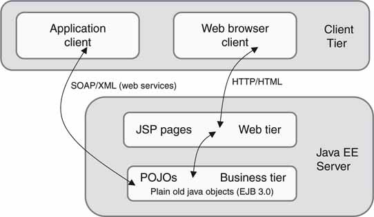
Why implement a non-browser-based application client? Client-based application programs (written in the C++ or Java language, for example) provide a richer user interface than what is available using HTML with a browser. Browsers offer limited UI functionality for security reasons, e.g., no drag and drop for the most part although there are exceptions. There are trade-offs galore between these two methods, and each has found application spaces.
Many vendors offer JAVA EE-compliant programming environments: BEA’s WebLogic, IBM’s WebSphere, JBoss (open source), and Sun’s Application Server Platform, to name a few.
NET AND JAVA EE INTEROPERABILITY: DREAM OR REALITY?
Integrating .NET and JAVA EE’s Web services is feasible. However, there are pitfalls to cross-platform integration.
• Standards are sometimes interpreted differently by the two platforms, although the conflicts are usually minor.
• Web service functionality is a common subset of both platforms. However, other middleware and messaging aspects do not have defined levels of interoperability. In this case, vendors supply bridges to cross the domains.
• Few developers are comfortable working in both environments.
4.4.3 The Burden to Choose
With so many frameworks and platforms, you might ask, “Which is the preferred one?” Well, the answer depends on many factors, some of which are application QoS performance, target HW, programmer experience/productivity, legacy IT infrastructure, choice of OS, cost of HW/SW, interoperability requirements, complexity, and available development tools. Any choice should factor in these considerations and more. The ideal platform should map onto your overall requirements list. Both of these programming paradigms exist in the much larger context of virtualized servers, networks, and storage. The next section will consider these leading-edge technologies.
4.5 METHODS OF VIRTUALIZATION
We are familiar with the world of physical clients, networking, servers, and storage. Given any configuration of user applications (SW and HW) and client loading, chances are some of the resources are underutilized. This implies wasted energy (not green) and inefficiently used compute-and-storage capacity. Is there a strategy to improve these metrics? Fortunately, there is: virtualization.
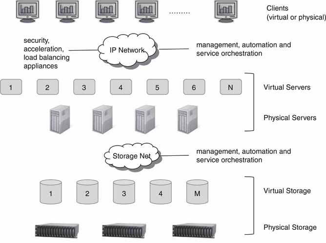
Virtualization is the creation of a virtual (rather than physical) version of something, such as an operating system, a storage partition, or a network resource. Virtualization hides the physical characteristics of a resource from its users. So, a server or storage device can appear as multiple virtual resources. Figure 4.21 shows layers of physical resources and the virtual versions that use these physical devices.
FIGURE 4.21 The virtual data center.
Some positive contributions provided by virtualization follow.5
• Virtualization provides for improved overall device utilization. The typical increase expected (servers) is 15 to 80 percent.
• Fewer physical devices are required (servers, storage, etc.). Virtualization enables you to reduce hardware and operating costs by as much as 50 percent.
• Floor space utilization efficiency is improved in the data center.
• It is greener. All electricity consumed by servers generates heat; heat is extracted with cooling that takes ~125 percent more electricity.
• Virtualization enables you to isolate applications within virtual servers. This improves QoS and update testing.
• It reduces the time to provision a new server by 70 percent.
• Virtualization completely changes how the IT data center is configured and provisioned. The more automation, the more efficient the operations.
• Virtualization enables you to deploy multiple operating system technologies on a single hardware platform; you can run Microsoft Vista on top of Linux, for example.
The advantages are compelling, and virtualization is becoming the “musthave” technology for the data center. IDC forecasts that, in 2010, 1.7 million physical servers will be shipped to run virtual machines. To appreciate what virtualization can accomplish, experiment with VMware’s TCO/ROI calculator at www.vmware.com/products/vi/calculator.html.
The complete virtualized data center of Figure 4.21 is not often fully implemented. Virtual servers and associated management systems (automation) are the most mature elements in the picture. What about networking? Case in point: Cisco’s VFrame product provisions data center resources by integrating orchestration and control intelligence into the infrastructure that interconnects resources together. Storage virtualization is available using a SAN, for example, but more functionality is required to mesh with other virtual elements. See the Snapshot “Virtual Arrays Within an Array.”
For many real-time A/V applications, using virtualized elements is problematic. Why? Real-time performance (I/O, codecs, editing, etc.) is not always guaranteed by the major providers of virtualization solutions. Time-insensitive applications (MAM, search, management, converters, and so on) are a sweet spot for virtualized servers, networking, and storage.
Detailed coverage of virtualized networking and storage is beyond the scope of this book. However, a short overview of server virtualization technology is of value.
VIRTUAL ARRAYS WITHIN AN ARRAY
In some cases, dividing up SAN storage among separate clients/servers running applications offers subpar performance. Why? One storage attached server may hog the resources such that other connected devices receive a degraded storage QoS. Administrators sometimes solve this problem using a DAS attach per server or application. This yields an optimum storage QoS per server/application. Or, they divide up a SAN into physical domains yielding a carved-out equivalent DAS. Neither of these is ideal, since a DAS is always more management intensive and less flexible than a SAN.
One approach to this problem is to define one or more virtual arrays (VAs) or virtual domains within a storage system. Each VA offers application isolation and a QoS contract per application or server. So a SAN could be divided into multiple VAs, each with its own defined operational characteristics. Technically, creating a VA is not trivial while still maintaining all the goodness of a SAN. You might imagine a demanding video application sharing a SAN with, say, a business application with no resource conflicts. Companies such as 3PAR offer SAN storage with managed virtual domains.
4.5.1 Under the Hood: Servers
A virtual server (VS) is built with software and uses the physical resources of CPU, memory, and I/O to provide independent operating environments. Figure 4.22 shows the two main types of virtual server design. Both enable the equivalent of N virtual servers per hardware platform. N can be large, so systems with 20+ virtual servers are possible. The sweet spot has settled in around 5–7 per hardware platform. Applications don’t know they are running in a virtual environment for the most part, although exceptions exist. Sharing I/O is a challenge, and this is one reason for two types of architecture.
FIGURE 4.22 Client/server virtualization methods.
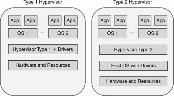
The key technology in server virtualization is the hypervisor. This is a thin layer of software that runs directly on the hardware (type 1) or a host OS (type 2). This software layer needs to be lean; otherwise, it will adversely affect application performance. It consumes precious CPU cycles interpreting each application layer OS call. Hypervisors are resource managers and enable many upper-layer operating systems to run simultaneously on the same physical server hardware. Some important features of a virtual server are as follows:
• N different user-level OSs (Windows, Mac OS, Linux, others) can run independently on the same hardware. Each of these OSs can support one or more user applications.
• The hypervisor is supported on X86 and Power PC architectures most commonly.
• A VS can be created or decommissioned at will. As user workloads change, IT staff (or automation) can configure the VS environment as needed. This is key to improving HW utilization and reducing the number of physical servers in a data center.
Type 1 hypervisors (a native virtual machine) provide higher performance efficiency, availability, and security than type 2 (a hosted virtual machine). Note that this method has fewer layers of software, and the hypervisor layer must provide the device drivers. Type 2 can be used on client systems with an existing OS, such as running Windows on a Mac OS. See www.parallels.com and Microsoft Desktop Virtualization for examples. Type 2 is also an advantage when a broad range of I/O devices is needed, since the host OS often has excellent driver support.
IBM, Microsoft, VMware, and Xen.org (Citrix) are among the leaders of server and client virtualization. See, too, http://en.wikipedia.org/wiki/Comparison_of_virtual_machines for a deep dive comparison of solutions.
What will the affect of virtualization be on the data center? A 2008 press release by Gartner stated, “Virtualization will be the highest-impact trend changing infrastructure and operations through 2012. Virtualization will transform how IT is managed, what is bought, how it is deployed, how companies plan and how they are charged.” So, the media enterprise will be dragged into this future with the possible exception of some high-performance A/V appliances—video I/O, real-time graphics engines, editors, and so on. In the final analysis, the virtualized media enterprise will offer operational efficiencies and cost savings of lasting value.
4.6 OPEN SOURCE SOFTWARE
The basic idea behind open source programs is simple. When masses of motivated freelance programmers are enabled to improve and modify code and then redistribute their changes, the software evolves. If the number of programmers is large, then the speed of software evolution is astonishing (Raymond). Open source provides free access to program source code. Licensing is required for most open source code, but the restrictions are not onerous. Changes are well controlled, tested, and folded into the next revision. The biggest open source project space may be found at SourceForge (http://sourceforge.net) with ~103 K registered projects. Many of these are developed by professional programmers, and the quality is excellent. Scan the SourceForge site for A/V tools and applications to see the variety of available software.
Gartner predicts that, by 2011, 80 percent of commercial software will contain open source code. Selecting an open source application depends on several factors. One, does it meet your needs? Seems obvious, but what this means is you should not select based on a staff zealot who hates vendor X in preference to open source. Two, is the distribution mature, is it sell supported, and does it meet your risk/reward ratio? Three, is your application mission critical? Open source can meet this need, but you need to be rigorous in testing before selecting.
Among open source code, LAMP is a set of programs commonly used together to run Web sites. LAMP is an acronym for Linux, the operating system, Apache, the Web server, MySQL, the database system, and the PHP serverside scripting language. Apache is used by ~65 percent of Web sites worldwide by some estimates. MySQL (www.mysql.com) is the most used open source database.
On the development front, Eclipse (www.eclipse.org) is a popular Java/JAVA EE integrated development environment. JXTA (www.jxta.org) is a set of protocols for building P2P applications. Interestingly, JXTA is short for juxtapose, as in side by side. It is a recognition that peer to peer is juxtaposed to the client/server model. Of general interest is the OpenOffice Suite (www.openoffice.org), which provides desktop productivity tools.
Expect to see more open source programming included with A/V vendor solutions. At present there are no “killer app” open source programs for the professional A/V space. If a critical mass develops, one day we may see something like MyTraffic, MyAutomation, or even MyVideoServer as an open source program. One interesting Linux-based, open source NLE application is Cinelerra (http://cinelerra.org).
4.7 HIGH-PERFORMANCE REAL-TIME SYSTEMS
For many A/V applications, real-time performance is the paramount feature. There are several ways to achieve this, and this section outlines the main aspects of RT systems for A/V. While it is true that not all C/S implementations are suitable for RT A/V applications, some are a perfect match. Some of the important themes are the RT OS, multimedia programming extensions, GPU acceleration, and 64-bit CPUs. Let us consider each of these next.
4.7.1 Achieving Real-Time OS Performance
The most common RT system implementation uses the standalone architecture with a dedicated OS. General-purpose, Windows-based (XP, Vista, Server 2008) products can achieve excellent RT performance, despite the bad rap they sometimes get for long-term reliability in normal use. This does not anoint the Win/OS as a real-time operating system (RTOS). Instead, for some selected applications, the OS meets the performance needs for A/V. For years vendors have built mission-critical, RT A/V applications with the Win/OS. What is the trick?
For one, you should run only the target A/V application—all others are persona non grata. Running unessential background applications (spyware, calendars, instant messaging, etc.) is a recipe for poor A/V client performance. In general, the more insular the application, the better its performance. Another trick is to set the OS priority of the target application for maximum utilization. Fine-tuning caching and networking also improves performance. With these precautions, the Win/OS (Linux and the Mac OS, too) supports A/V applications with excellent performance, long-term reliability, and delivery quality. An alternative is to base the application platform on a true RTOS, such as Wind River’s VxWorks, LynxOS, Real-Time Linux, and Real-Time Specification for Java (RTSJ). An RTOS guarantees excellent OS response times for A/V applications. The RTOS environment runs as an embedded system and does not offer general-purpose computer resources. Embedded RTOS systems are single-minded and perform exceptionally well under the stress of RT workloads.
Consequently, some A/V product vendors have chosen the RTOS approach. For example, Chyron’s Duet Graphics platform uses VxWorks. The choice of RTOS versus non-RTOS depends on many factors, and there are trade-offs for each camp.
4.7.2 Multimedia Extensions and Graphics Processors
Digital signal processors (DSPs) have long been a mainstay for compute-intensive operations. Just a few years ago, real-time A/V processing used DSP chips or dedicated hardware. Thanks to Moore’s law, the momentum has shifted from the dedicated DSP to the general CPU for standard definition video and some HD processing. Although DSP processors are still in demand for some applications, Intel/AMD processors, with DSP-like multimedia extensions (MMX), can perform RT A/V operations without resorting to special hardware. The PowerPC has also been optimized for multimedia operations with its Velocity Engine.
Some vendors are using software only for real-time SD MPEG encoding/decoding and HD decoding. For HD encoding (especially H.264), hardware acceleration is often needed. Today it is possible to build a four-channel video server with every A/V operation performed in software, including all SD/HD decoding and encoding using only one quad core CPU.
Some vendors are using high-performance video/graphics cards (designed for PCs) for video processing, 2D/3D imaging, and font shading. The key ingredient here is the embedded graphics processing unit (GPU). GPUs are being used as graphics accelerators for CPU-sited algorithms. The combination of CPU software algorithms plus GPU graphics acceleration provides amazing RT video processing power.
4.7.3 64-Bit Architectures and Beyond
The jump from 32- to 64-bit processing represents an exponential advance in computing power, not just a factor of two. With 32-bit registers, a processor has a dynamic range of 232, or 4.3 billion. With 64-bit registers, the dynamic range leaps to 264, or 18 billion billion. Compute speed and memory addressing range are improved. Many popular CPUs offer 64-bit modes. Microsoft has a 64-bit version of XP/Vista and Windows Server. These are joining the mature UNIX/64 and Linux/64 choices. Few A/V applications have been written to take advantage of 64-bit computing, but this will change as 64-bit computing becomes more mature. Porting a native 32-bit application to take advantage of 64 bits is a painful experience, so most vendors will not do it. However, new applications may well be written for the 64-bit mode.
Another way to improve compute performance is to use multiple processors. If N CPUs are ganged together, the overall compute power increases. Appendix C outlines grid and cluster computing concepts.
4.8 SOFTWARE MAINTENANCE AND SYSTEM EVOLUTION
It is inevitable that software-based applications and systems will need bug fixes and upgrades. The larger the application, the more likely it will take on a life of its own. Indeed, software needs maintenance just as hardware does. Figure 4.23 outlines several questions you should ask when purchasing vendor software. Do not underestimate the effort to keep the software running smoothly. Also always ask about hot upgrades. Large, mission-critical systems have many elements; make sure that any one element can be upgraded—while the system is running—without affecting the operation of the other pieces.
FIGURE 4.23 Software maintenance factors.
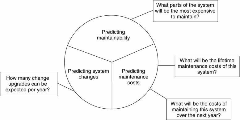
Source: Software Engineering 7 (Sommerville).
4.8.1 Lehman’s Laws
In 1972 Lehman and Belady (Lehman) published their laws of software evolution. These are reprinted in Table 4.2. They studied the history of successive releases of large programs. They found that the total number of modules increases linearly with release number but that the number of affected modules increases exponentially with release number. What does this mean? Repairs and enhancements tend to destroy the structure of a program and to increase the entropy and disorder of the system. More time is spent repairing introduced flaws and less time on developing truly useful new features.
Table 4.2 Lehman’s Laws of Software Evolution
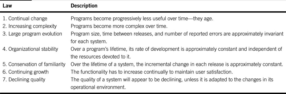
These laws are especially useful for program developers but also for end users. For example, law #6 adds a sense of realism to a product’s functionality. Users will be disappointed if the vendor does not regularly add features to the product. Law #7 indicates that as a facility changes, the unmodified products will appear less capable unless they are updated to fit into the new environment. So, when you are selecting a product, it is wise to check with the vendor for the planned upgrade schedule. The larger the software effort behind a product, the more likely that Lehman’s laws will apply. Note that these laws apply to large programs and do not necessarily apply in exactly the same way for small- or medium-size programs. Nonetheless, the principles have some applicability to most programming projects.
4.9 IT’S A WRAP—A FEW FINAL WORDS
A/V performance is tied to software performance—and increasingly so. While it is true that many contemporary A/V products use the standalone architectural model, expect to see distributed systems, especially Web services, applied to A/V systems. Non-RT designs have relaxed QoS levels and are easier to build than RT designs. However, RT distributed systems will become part of the A/V landscape as developers become more confident and experienced with service-oriented architectures.
Software evaluation, selection, configuration, and maintenance are key to a smoothly run media organization. An educated A/V staff will be an agile staff. The future of A/V systems’ performance, scalability, reliability, manageability, and flexibility lies in software and networked systems. Keep your saw sharp in these areas.
1 Although our focus is on software, the concepts discussed in this section relate equally to computer systems in general, so the terms software system and computer system are used interchangeably.
2 In this chapter, the term C/S is used to represent client/server and the relationship between these two elements.
3 Don’t confuse Web services with a Web server; they use completely different software models. The differences are outlined in the course of this chapter.
4 Web services definitions were derived from a course presented by IBM.
5 See various white papers at www.vmware.com/solutions, http://xen.org, and www.microsoft.com/virtualization.
REFERENCES
Barry, D. Web Services and Service-Oriented Architectures: The Savvy Manager’s Guide: Morgan Kaufmann, 2003.
Cummins, F. Enterprise Integration Chapter 10: Wiley, 2002.
McCarthy, S. ENIAC: The Triumphs and Tragedies of the World’s First Computer: Walker & Company, 1999.
Erl, T. Service-Oriented Architecture: A Field Guide to Integrating XML and Web Services: Prentice Hall, 2004.
Graham, S., et al. Building Web Services with Java: Making Sense of XML, SOAP, WSDL, and UDDI (2nd edition): Sams, 2004.
Footen, J., & Faust, J. The Service-Oriented Media Enterprise Chapter 3: Focal Press, 2008.
Lehman, M.M. & Belady, L.A. An Introduction to Program Growth Dynamics in Statistical Computer Performance Evaluation. W. Freiburger (ed.), Academic Press, New York, 1972, pp. 503–511.
Milojicic, D., et al. Peer-to-Peer Computing, HP Labs Research Report, www.hpl.hp.com/techreports/2002/HPL-2002-57R1.html, March 8, 2002.
Orfali, R., et al. Essential Client/Server Survival Guide: Wiley Press, 1994.