
CHAPTER 7
Media Systems Integration
CONTENTS
7.1.1 Examples of the Three Planes
7.2.2 Working with MXF and Interoperability
7.3 Advanced Authoring Format (AAF)
7.3.1 Methods of AAF File Interchange
7.3.2 AAF Reference Implementation
7.4.1 Metadata Standards and Schemas for A/V
7.4.3 ISAN and V-ISAN Content ID Tags
7.4.4 ISCI and Ad-ID Identifi cation Codes
7.5.2 MAM Functions and Examples
7.5.3 Using DRM as Part of a MAM Solution
7.6 The Fundamental Elements of Media Workfl ows
7.6.2 The Process Orchestration Element
7.6.4 The Workfl ow Agility Element
7.8 It’s a Wrap—A Few Final Words
7.0 INTRODUCTION
The previous six chapters outlined the core elements of IT-based A/V systems design, including file-based technologies, streaming, storage, servers, HA methods, software platforms, and networking. This chapter ties these elements together to create world-class media workflow systems. Additionally, the foundations of media types, metadata, control methods, nodal management, and asset management are introduced to more fully describe networked media systems.
As a house is made of bricks, so a media system is composed of its constituents. But a pile of bricks does not make a house any more than a collection of servers and a network create a media system. It is the organization of the bricks that makes the house livable. So what are the organizational principles of A/V systems? Let us start by describing the three planes.
7.1 THE THREE PLANES
Is there a unified way to simply categorize all the disparate elements of an A/V system? Figure 7.1 is a pictorial of the three disciplines commonly used in most AV/IT systems: data/user, control, and management planes. Each plane has an associated protocol stack—LAN (TCP/IP), SDI, audio, or other as depicted. Figure 7.1 shows alternate stacks per plane depending on whether the system is based on traditional A/V or networked media. As a result, A/V (data plane) may be passed over an SDI link in one case or TCP/IP networking used in another. Due to the legacy of older control and management protocols, the RS-232/422 links will be in use for years to come. The stacks in Figure 7.1 are representational and not meant to document every possible stack for each plane. Although the planes are independent, they are often used together to accomplish a specific operation. For example, commanding a video server to play a file will involve both user and control planes. Here are brief descriptions of the three planes.
FIGURE 7.1 The three planes: data/user, control, and management.
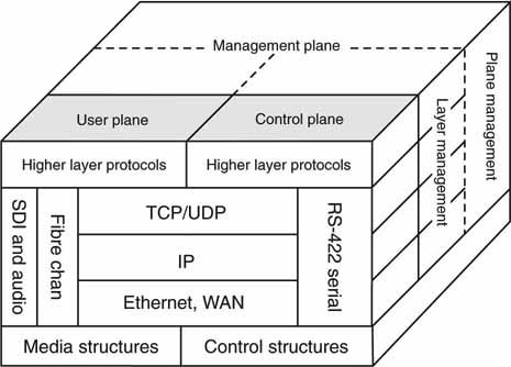
• Data or user layer: Moving A/V data across links in RT or NRT is a data plane operation. The data types may be all manner of audio, video, metadata, and general user data. This plane is alternatively called data or user. One term describes the data format aspects of the plane, whereas the user handle denotes applications-related aspects, not shown, at the top of the stack. Editing a video that is stored on a remote networked device is a user plane operation.
• Control layer: This is the control aspect of a video system and may include automated and manual protocols for device operations (master control switcher, video server, video compositor, router, VTR, archive, etc.), live status, configuration settings, and other control aspects. This plane includes control applications, not shown, at the top of the stack.
• Management layer: This layer provides device management for alarms, warnings, status, diagnostics, self-test, parameter measurements, remote access, and other functions. This plane includes management applications, not shown, at the top of the stack.
Another way to view the three planes is illustrated in Figure 7.2. In this case, a general A/V device is divided into three functional domains. For sake of viewing, the LAN ports are repeated for data, control, and management, but in reality there may be only one LAN port and all three functional areas share the LAN. However, in some cases the management LAN port would be a second port to completely isolate management from applications-related operations. Why do this? Device management operations should be non-intrusive and not affect the A/V operations in any way. The separate LAN port makes it easier to build and operate non-intrusive management operations. For example, blade servers typically have a dedicated Ethernet port for management use (see ).
FIGURE 7.2 The three planes: physical view of client side.
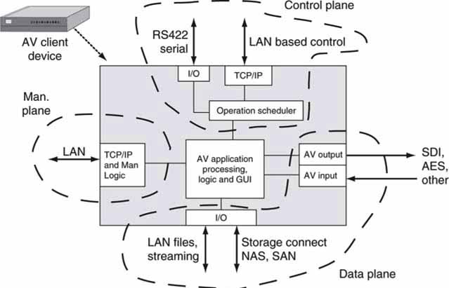
In some cases, LAN isolation may apply to the control layer too. The choice of one, two, or three LAN ports is left up to the equipment manufacturer. Of course, choosing more than one LAN port can complicate the external network infrastructure if different QoS requirements are placed on each LAN connection.
7.1.1 Examples of the Three Planes
Complete industries exist to serve these layers. For example, automation companies such as Avid/Sundance, Florical Systems, Harris Broadcast Communications, Hitachi Systems, Masstech Group, Omnibus Systems, Pebble Beach Systems, Pro-Bel, SGT, and others sell products for the control layer (see Section 7.7). Traditional video equipment companies sell data/user (A/V equipment of all sorts) plane products. Device management solutions have traditionally been vendor specific, but Miranda (iControl) and Snell & Wilcox (RollCall), for example, offer general device management solutions, despite a lack of industry-wide standards. Let us consider a few examples in each plane.
7.1.2 The Control Plane
Traditionally, the control layer has been forged from custom solutions and lacks the open systems thinking that is prevalent in the general IT world. For example, many A/V devices still rely on RS-422-related control protocols and not LAN-based ones. For controlling video servers, the Video Disk Control Protocol (VDCP) has been used for many years over the RS-422 serial link, and many manufacturers are reluctant to move away from it, despite several vendor attempts to introduce LAN-based control protocols. The common Sony BVW-75 VTR control protocol is also in wide use and is RS-422 based. At present, there is no LAN-based A/V device control protocol sanctioned by SMPTE, although all automation and server companies have developed private LAN-based protocols. For example, some of the current vendor-specific LAN control protocols (and APIs) for networked A/V devices (especially servers) are as follows:
• Avid’s Interplay Web services APIs
• Harris’s VDCP over LAN
• Media Object Server (MOS) from Associated Press (AP) and the MOS user group
• Omneon’s Server Control protocols: Player Control API and Media API
• Omnibus’s G2/G3 Control protocols
• ClipNet protocol from Quantel
• Thomson/GVG Profile Server and K2 Server native control
• Sony, SeaChange, and others, which offer proprietary LAN-based control protocols
Vendors have developed device-frame-accurate, custom LAN-based protocols for controlling servers, file transfer, logo inserters, real-time compositors, A/V routers, character generators, format converters, and more.
For now, these incompatible protocols will coexist in AV/IT systems. Of course, this is not ideal and creates interoperability issues, but until SMPTE or some industry group standardizes a method(s) or a de facto one is selected by the market, there will be confusion and competition among protocols.
7.1.2.1 The MOS Example
Media Object Server (MOS) is a protocol based on message passing and not one for direct device control. The MOS protocol was designed by the MOS Group for story list management in A/V devices. It has achieved excellent market acceptance as an IP-based protocol. The MOS Group is an industry body composed of representatives from many industry companies. The protocol is applied to news production for creating, organizing, deleting, and modifying the news “rundown list” of stories for a newscast. Video playback servers, character generators (CGs), video compositors, teleprompters, and even robotic cameras need to know what activity to do per-story entry. MOS manages and synchronizes the activity lists across devices.
The following is a sample list of device activities needed to run story #3 for the newscast:
• Story 3 needs a lower third text crawl, so the CG has a rundown story entry “Story 3, text crawl, ‘Snake River overflows banks …’ “
• Story 3 requires an over-the-shoulder video clip of the swollen river, so the video server has a story entry “Story 3, play clip Snake-Flood.dv.”
• The teleprompter has a rundown entry “Story 3, file Snake-Flood.txt.”
The MOS protocol works in the background in non-real-time creating rundown activity lists in all equipment. It is not considered a real-time control protocol. At story time, a separate scheduling engine (or manual operation) triggers the individual devices to execute the list entry for story #3, thus creating a well-orchestrated harmony across all equipment. List management is an ideal activity for an IP-based protocol because no frame-accurate video control is required. See www.mosprotocol.com for more information.
With the success of MOS, industry leaders are looking at ways to use the framework of the protocol (XML message passing) for general, real-time, frameaccurate, and device control over IP networks. Of course, new commands are needed, including the prequeuing methodology discussed here.
7.1.2.2 The Broadcast eXchange Format (BXF)
BXF is a message passing protocol and should not be confused with MXF (described later), an A/V essence and metadata wrapper format. Although the acronyms are similar, the formats are designed for completely different purposes. In most broadcast facilities MXF and BXF will happily coexist. So, what is BXF?
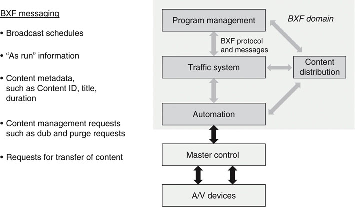
BXF is standardized as SMPTE 2021 and defines the communication of three basic types of data:
1. Schedule and “as-run” information
2. Content metadata
3. Content movement instructions
BXF is based on the XML data-interchange standard. It provides advantages to the broadcast TV facility (and similar operations), including the following:
• A single method of exchanging data among these four domains: program management, traffic, automation, and content distribution
• Support for file- and message-based (dynamic) data exchange
• Increased integration of related systems
• Extended metadata set for data exchange
BXF is not a real-time device control protocol!
Before BXF, the four domains communicated with a hodgepodge of vendorcustom protocols. This resulted in incompatible message and data-passing methods and vendor lock-in. BXF is a breath of fresh air for interoperability and open systems; it will be required for all new installations. MOS and BXF have some overlap today, and there is potential for consolidation in the future (Figure 7.3).
FIGURE 7.3 BXF messaging partners in broadcast operations.
Next, let’s consider what methods are needed to use a LAN and still achieve real-time control.
7.1.2.3 Command Execution Modes for Device Control
Let’s start with a simple categorization of control accuracy and timing modes that are commonly used. Figure 7.4 illustrates five control events labeled A to E. The vertical axis is roughly related to event timing accuracy from the inception of a command at time T0 until command execution. The horizontal axis is time in increments of integer video frame counts. For example, a class A command issued at time T0 results in an event occurring (for example, video server playout starts) at T1. This command type is “immediate,” since the event occurs at the start of the next whole video (or audio) frame.
FIGURE 7.4 Command/action timing models.
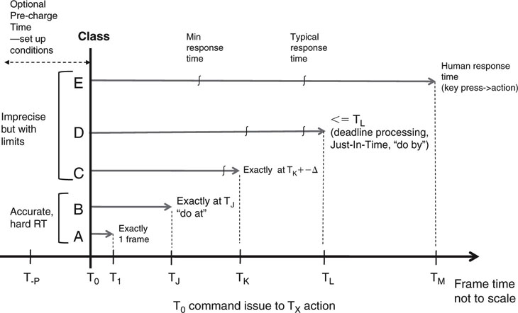
Control class B requires that the command issued at T0 is executed precisely at time TJ. This may be anywhere from 2 frames to thousands counting from T0. This method is very useful when scheduling events to execute in the future: do-this-at-TX. This command type is typically underutilized in broadcast facilities. Class C is a version of B with a small allowable jitter in the command execution time.
Class D is a bounded control scenario. This class should be used when an operation’s completion is required (convert file ABC to MPEG4) before some deadline time TL. This class relaxes timing control considerably. Many facility operations can be designed to schedule operations to be complete before a deadline. File conversion, indexing, and transfers are a few operations that may be scheduled by a class D event. In general, don’t use classes A or B if D meets your needs.
Finally, class E is human timed: “Ready on camera 3 … take 3.” It’s not frame-accurate timing but is bounded by human reaction speeds. For the most part, we care about classes A and B when commands are sent over a LAN.
7.1.2.4 Techniques for Control over IP
Why have LAN-based device control protocols been adopted so slowly? Most traditional RS-422 serial device control protocols are video frame accurate by the nature of the point-to-point wiring. There is never congestion or meaningful latency using a serial link. It is proven, it works, and it is still in wide use. Nonetheless, over time, LAN will replace dedicated RS-422 links. So, let’s look at two strategies for using a LAN to achieve frame-accurate A/V device control. One is based on class A and the second on class B timing. Both control examples are shown in Figure 7.5. Let’s call them type N (do this now, based on class A) and type S (scheduled, based on class B) methods. Note that the timing references in this figure are different from those in Figure 7.4 ; T0 is the desired execute time.
FIGURE 7.5 Type S and N models for device control over LAN.
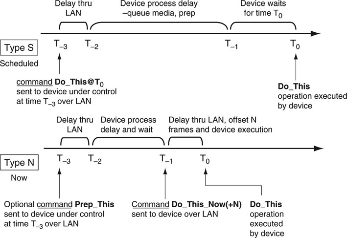
7.1.2.5 Type S—LAN-Based Scheduled Real-Time Control Method
The type S model is based on prequeuing one or a list of actions in the target device. Queued items range from a simple command to play a clip to a complex multielement video composite. Each queued item has an exact, frame-accurate, future execute time, T0. As long as the device reliably receives the command instructions adequately before T0, then any IP jitter or packet loss is of no consequence. When the device under control is allowed to, in effect, schedule the future operation, any small LAN delays will be absorbed. Of course, the controlling intelligence must cooperate by sending commands before they are to be executed at T0.
Reviewing Figure 7.5, the type S timeline shows three critical periods from the initial command reception to command execution. A Do_This@T0 command (with This implying some device operation) is sent to target device at T−3. Delay through a small LAN network is normally <1 ms (much less than one frame of video) if there is no router congestion. The target and sender device TCP/IP processing delay are both in series with the LAN delay, which can be significant if not managed. The next period (T−2 to T−j) is allocated for the device to queue any A/V media and prep for the desired action at T0. This may take from one to N video frames based on traditional serial control methods. In the world of VTRs, this is called the preroll time. Next, there is a wait period until T0 occurs referenced to a time code clock (usually synced to the facility time-of-day clock). At T0, the desired operation is executed, frame accurately. The T−j until T0 delay can range from one frame to hours.
Figure 7.6 illustrates a video server with a deep queue using type S control. The external storage does not require a low latency response, as the server has ample time to queue the clips. Of course, the average storage access bandwidth must meet the needs of the server. Type S does not require a deep queue (one level may be sufficient), but the deeper the queue, the more forgiving the overall system is to temporary LAN and storage access anomalies. In fact, a type S control schema considerably enhances overall system reliability if queuing is used judiciously.
FIGURE 7.6 Deep queuing with quasi-RT storage and type S control.
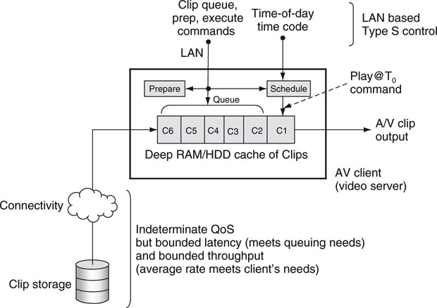
A type S control has ideal frame-accurate characteristics as long as prequeuing timing is observed. The minimum practical time from command reception to execution is less than one frame of video. The maximum time depends on several factors, such as queuing time and the QoS of any external storage, and may require 7s or more for reliable, repeated execution. Many typical operations (video server plays Clip_C1, for example) need 3 s or less from T−3 to T0. If the target device does not support scheduled operators or the application is not suited for this model, then type N may be used.
7.1.2.6 Type N—LAN-Based Immediate Real-Time Control Method
For the type N scenario, the concept is based on a Do_This_Now command plan. In some cases, such as selecting signal routing, immediate execution is required with no prequeuing or prescheduling possible as with a type S. A low LAN delay is crucial (less than one frame of video) for immediate execution of some commands. For other scenarios, prequeuing is required, so a Prep_This command is issued before the Do_This_Now is executed. Figure 7.5 shows the prep command in the type N timeline. Command execution is not prescheduled as with a type S, but follows the Do_This_Now command being received by the target device. In general, the execute command needs to have an offset of N (0,1,2,3,4, …) frames in the future to allow for the frame-accurate alignment of other coordinated A/V devices—each with a potentially different execute latency. As a result, Do_This_Now(+N) is a more general case where N is device specific. This is not a new problem and exists with RS-422 command control today.
There may be several prep commands issued before the corresponding Do_This command. For example, the sequence of Prep_This_1, Prep_This_2 may precede a Do_This_2_Now followed by a Do_This_1_Now execution sequence. The order of execution is not foreordained. The most crucial time period is from T−j to T0 and should be less than one video frame (~33 ms with 525-line video). Modern LANs can meet this requirement.
For most type S and N control cases, the relaxing of storage access latency implies that the storage and connecting infrastructure is easier to build, test, and maintain. Plus quasi-real-time (latency may on occasion exceed some average value) storage is less expensive and more forgiving than pure RT storage. Of course, if the workflow and reliability demand immediate access and playout without the advantage of deep queuing, then the storage QoS will be rigid. There is no free lunch, as prequeuing clips in local client memory (RAM usually but disk is also possible for some cases) adds a small expense. A client cache that can hold 50 Mbps encoded clips for 1 min needs to be at least 375 MB deep. This is not a huge penalty, but it is a burden. Also, the logic for deep queuing may be nontrivial, and some automation controllers may not be designed with deep queuing in mind. Also, if the playout sequence changes in the last seconds (news stories), then the queue needs to be flushed or reordered, which adds complex logic to the workflow. See the section on user data caching in Chapter 3B for more insight into the art of caching.
It is inevitable that LAN methods will replace legacy serial links. With certainty, the generic Do_This@T0 and Do_This_Now with associated deep queuing/prep commands will be implemented. Many industry observers predicted (hoped!) that LAN control would completely replace the serial link (RS-422) by 2009, but this has not happened yet. Next, let us consider the management plane.
7.1.3 The Management Plane
The management plane (see Figure 7.1) is the least mature of the three because there are too few A/V product management standards to gain the momentum needed to create a true business segment. The general IT device management solution space is very mature with hundreds of vendors selling to this domain. However, because A/V equipment manufacturers have been slow to develop standardized management plane functionality, many A/V-specific devices are managed in an ad hoc manner. SMPTE is encouraging all vendors to assist in contributing to common sets (general and per device class) of device status metrics, but the uptake has been slow. See for a complete coverage of the management plane.
7.1.4 The Data/User Plane
The data/user plane is the most mature of the three, with many vendors offering IT-based NLE client stations, A/V servers, browsers, video processors, compositors, storage systems, and other devices. For example, Sony offers the XDCAM camera family (field news gathering) using the Professional Optical Disc (there is a Flash card version too), Panasonic offers the P2 camera family using removable Flash memory, and Ikegami offers the EditCam series with a removable HDD. These are a far cry from the videotape-centric cameras of just a few years ago. The P2 and XDCAM have LAN ports for offloading A/V essence,1 usually wrapped by MXF with included metadata.
Generally, most recently developed A/V devices show a true hybrid personality with traditional A/V connectors, a LAN port, and other digital I/O ports such as IEEE-1394 or USB2. Incidentally, high-end P2 cameras support five 32 GB removable Flash cards and a gigabit Ethernet port supporting download rates of 640 Mbps. This storage is equivalent to 200 minutes of HD 1080/24P content. There are interesting and compelling trade-offs among these three camera styles.
The types of data plane A/V essence in use are varied from uncompressed digital cinema production quality (~7 Gbps) to low bit rate compressed proxy video at 200 Kbps. Audio too can range from multichannel, 24-bit uncompressed, 2.3 Mbps per channel to MP3 (or a host of others) at 64 Kbps. Due to the wide variety of A/V compression formats, video line rates, and H/V resolutions, achieving interoperability among different vendors’ equipment can be a challenge. Although the data plane is standardized and mature in many aspects, creating workflows using different vendors’ equipment can be a challenge.
The protocol aspects of this plane include network protocols such as TCP/IP, storage access protocols such as SCSI and iSCSI, and file server access protocols such as NFS and CIFS. The main goal of access protocols is to get to data—the A/V and metadata gold that resides on disk arrays and archive systems. These protocols are discussed in detail in Chapter 3B.
The data structures layer is rich in variety and detail. SMPTE and other standard bodies have devoted hundreds of standards to describing these structures. Chapter 11 specializes in the A/V data/user plane with coverage of the fundamentals of A/V signal formats, resolutions, interfaces, compression, transmission formats, and many more. You may want to read Chapter 11 first before continuing here if you are unfamiliar with the basics. If not, let us move on to wrapper formats, including MXF, AAF, and XML. See (SMPTE 2004) for a good tutorial series on MXF and AAF.
7.2 WRAPPER FORMATS AND MXF
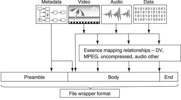
The A/V industry is not lacking for file formats. A laundry list of formats confronts designers and users daily: MPEG1, 2, 4; H.264; VC-3; DV (25, 50, 100 Mbps); Y’CrCb; RGB; audio formats; and the list continues. As shown previously, files are indispensable when acquiring, logging, browsing, storing, editing, converting, transferring, archiving, and distributing A/V materials. Is there a way to tame the format beast? Can we select one format that all users would support? If so, then interoperability would be a snap, and file exchange between users would rarely hit a snag. Additionally, A/V equipment interoperability, vendor-neutral solutions, and one archive format all follow when a universal file format is chosen. Despite the desire for interoperability, very few users would accept a one format policy. Why not? Each format has its strengths and weaknesses. Depending on business needs (acquisition format, cost, quality, bandwidth, simplicity, legacy use, etc.), format A may be a better choice than format B. In the end, the one format policy cannot be legislated, despite all its benefits. Fortunately, there is an acceptable trade-off: a standardized, universal, professional wrapper format. A wrapper does exactly what the name implies—it wraps something. In the broadest sense, that something may be A/V essence, graphic essence, metadata, or generic data. Like peas inside a pea pod, a wrapper is a carrier of lower-level items. A universal wrapper fosters interoperability between users and equipment at several levels. Figure 7.7 illustrates the concept of a wrapper. Note the various essence mappings into the wrapper file.
FIGURE 7.7 Example of a file wrapper format.
Concept: File interchange handbook, Chapter 1.
A wrapper format is not the same as a compression format (e.g., MPEG2 Elementary Stream). In fact, many wrappers are compression agnostic even though they carry compressed essence. The QuickTime.mov format from Apple is a wrapper. The ubiquitous.avi file format is a wrapper. A File.mov or File. avi that carries MPEG essence or DV does not disclose which by its file extension, unlike File.dv, which is always a DV format. Many A/V essence formats have documented mappings into file wrappers. The term essence agnostic is often cited regarding MOV, AVI, or MXF but is only partially true. The wrapper must provide for the underlying essence mapping with supporting official documentation. An undocumented mapping is useless. For an excellent reference to MXF and other file formats, see (Gilmer 2004) and also the SMPTE Engineering Guidelines EG-41 and EG-42.
Despite the existence of A/V wrappers, all legacy formats fall short of the needs of professional A/V. The ideal wrapper requirements for our needs are
• Open and standardized (QuickTime is not open or standardized)
• Supportive of multiplexed time-based media
• Supportive of multiplexed metadata
• Targeted for file interchange
• Essence agnostic in principle
• OS and storage system independent
• Streamable
• Extensible
Wrapper requirements were identified by the SMPTE/EBU Task Force report of April 1997. Following that, the ProMPEG Forum was formed to define and develop a wrapper format that met the requirement list given earlier. The initial work started in July 1999 and was called the Material eXchange Format, or MXF. After nearly 4 years of effort, the forum submitted its documents to SMPTE for standardization in 2003. In 2009, there are 31 MXF-related standards, proposed standards, and engineering guidelines. SMPTE 377M is the fundamental MXF format standard. MXF has been favorably embraced by the A/V industry worldwide. Of course, it will not replace existing wrappers or dedicated formats overnight. It will take time for MXF to gain enough steam to become the king of the professional A/V format hill. MXF is expected to have minimal impact on consumer product formats.
7.2.1 Inside the MXF Wrapper
There are two chief ways to view a MXF file: the physical layout and the logical layout. The physical view is considered first. Figure 7.8 shows the physical layout of a typical MXF file. The A/V essence, metadata, and optional index file (associates time code to a byte offset into the file) are all multiplexed together using basic key/length/value (KLV) blocking. KLV coding is a common way to separate continuous data elements and allow for quick identification of any element. The key is a SMPTE registered 16B Universal Label (SMPTE 336M) that uniquely identifies the data value to follow (audio, video, metadata, etc.). Length indicates the number of bytes in the value field. The value field carries the data payload, including audio samples, video essence, metadata, index tables, pointers, and more.
FIGURE 7.8 Physical views of a MXF file.
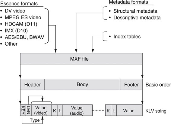
The KLV sequences are divided into three general groups: the header, body, and footer. The header contains information about the file, such as operational pattern (explained later), clip name, length, creator, aspect ratio, encoding rate, frame rate, and so on. This information is referred to as structural (in contrast to descriptive) metadata. The header also contains descriptive metadata that may be time synchronous with the A/V essence. The body contains A/V multiplexed essence. The A/V essence is mapped according to the rules per each data type. For example, MPEG (including MPEG1, 2, MPEG4 and H.264/AVC) has a mapping (SMPTE 381M), DV has a mapping (SMPTE 383M), AES/EBU audio has a mapping (382M), HD codec VC-3 has a mapping (2019-4), and so on. Most mappings locate each video frame on a KLV boundary for convenient, fast frame access, but there is no absolute requirement for this. Finally, the footer closes the file with optional metadata. Additionally, index tables (frame tables) are optionally included in the header, interleaved in the body, or stored in the footer.
7.2.1.1 MXF: The Logical View
The second way to view a MXF file is logically. In this case, the focus is on the organization of the information, not how it is sequenced in the file. Figure 7.9 (top) illustrates a very simple MXF file with only sound and video essence tracks. Of course, data are stored as KLV sequences, but the organization shows a File Package (FP) and Material Package (MP). By analogy, the File Package is the “input timeline,” a collection of files in effect, whereas the Material Package is the “output timeline”—how the MXF internal files are to be read out. The example shows the output to be a portion of the stored essence. A small amount of internal metadata sets the mark_in and mark_out points and is changed easily.
FIGURE 7.9 Logical views of a MXF file.
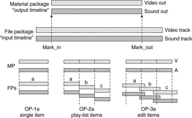
This is only the tip of the organizational iceberg of MXF, and much of its documentation is devoted to describing its logical layout. It is not hard to imagine all sorts of ways to describe the output timeline based on simple rules between the File Package and the Material Package. These rules are called Operational Patterns. Consider the following in reference to Figure 7.9:
• Single File Package, Single Material Package. This is the most common case, and the FP is the same as the MP. This is called OP-1a in MXF speak and is referenced as SMPTE 378M. An example of this is DV essence, with interleaved audio and video, wrapped in a single MXF file.
• Multiple File Packages, Single Material Package. This is case OP-2a
• (SMPTE 392M) and defines a collection of internal files (a, b, and c) sequenced into one concatenated output.
• OP-3a (SMPTE 407M) is a variation of OP-2a with internal tracks a, b, and c each having mark_in and mark_out points.
There are seven other operational patterns (2a, 2b, 2c, 3a, 3b, 3c, and OP-ATOM), each with its own particular FP to MP mapping. The simplest, OP-ATOM (SMPTE 390M), is a reduced form of OP-1a where only one essence type (A or V, not both) is carried. Many vendors will use this format for native on-disc storage but support one or more of the other OPs for file import/export. Frankly, the abundance of OPs makes interoperability a challenge, as will be shown.
7.2.1.2 Descriptive Metadata
A distinguishing feature of MXF is its ability to optionally carry time synchronous descriptive metadata. Other wrappers are not as full featured in this regard. An example of this type of metadata is the classic opening line of the novel Paul Clifford:
It was a dark and stormy night; the rain fell in torrents—except at occasional intervals, when it was checked by a violent gust of wind which swept up the streets, rattling along the housetops, and fiercely agitating the scanty flame of the lamps that struggled against the darkness.
—Edward George Bulwer-Lytton (1830)
It is not hard to imagine this text associated with a video of a rainy, nighttime London street scene. As the video progresses, the descriptive metadata text is interleaved scene by scene in the MXF wrapper. Once available for query, the metadata may be searched for terms such as dark and stormy and the corresponding video timecode and frames retrieved. The promise of descriptive data is enticing to producers, authors, editors, and others. The entire value chain for descriptive metadata is nontrivial: authoring the text, carrying text, storing searchable text separate from corresponding video, querying the text and retrieving corresponding video, editing the text, archiving it, and so on.
Our industry is struggling to develop applications that use metadata to its fullest potential. Because metadata span a wide range of user applications, no one vendor offers a comprehensive, end-to-end solution set. SMPTE has standardized several means to carry metadata inside a MXF wrapper and DMS-1 (Descriptive Metadata Schema, SMPTE 380M) is one such method. In addition, SMPTE has also defined a metadata dictionary (RP 210) with room for custom fields as needed. Interestingly, when Turner Entertainment documented its cartoon library, it invented 1,500 new terms to describe cartoon activities that rarely occur in daily life, such as stepping off a cliff, slowly realizing that the ground is far below, and then falling.
Several vendors support the budding metadata management world. A few tools in this space are MOG’s Scribe and MXF Explorer (www.mog-solutions.com), Metaglue’s Diffuser (www.metaglue.com), and OpenCube’s MXF Toolkit (www.opencube.fr). Do not confuse metadata management with digital asset management (DAM). DAM is considered later in this chapter. Incidentally, a free MXF SDK is available at www.freemxf.org.
7.2.1.3 The Group of Linked Files (GOLF) Concept
The overarching goal of MXF is to package data formats of various flavors under one wrapper using operational patterns to define the packaging. An archived program may include some or all of the following data types:
• Video tracks—one or more, SD versions, HD versions
• Audio tracks—one or more
• Descriptive metadata
• Closed caption files (per language)
• Descriptive narration files (per language)
• Proxy files—VC-1, VC-3, or similar low bit rate (A + V)
• AAF compositional metadata file
• Others (rights use, etc.)
MXF defines the wrapping rules for many of these data types, but not all of them. For example, the proxy and closed caption files may remain separate, never to be wrapped by MXF. The audio and video could be wrapped into a single MXF file; however, there are reasons to keep them discrete.
While it is true that most of the file types in the list may be wrapped into a single MXF file, at times it is wise to keep all these files separate. Using the concept of a master inventory file, all referenced files become linked together. Let us call this a group of linked files. A GOLF uses an inventory list to document how all other individual files in the list are (time) related. For access purposes, a user may retrieve all or parts of the program, including partial access within an individual file/track. By referring to a named directory, the user can easily move all its parts in total to another location without fragmentation.
Figure 7.10 shows an example of a GOLF for the program title “Basketball_Finals.” Notice that only the video tracks are wrapped in MXF using Op-ATOM, the simplest operational pattern. The inventory file is a key element and defines the contents of all the other files in the GOLF. The inventory file is MXF but does not carry any essence—only pointers to external essence and other data types. The inventory file creates a “smart directory” of sorts.
FIGURE 7.10 Group of linked files (GOLF) example.
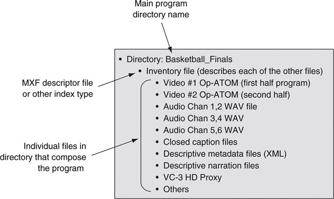
The GOLF files are accessed as a function of the needs of a workflow. For example, for A/V editing, the separate audio and video files are accessed as needed. For broadcast playout, the audio, video, and closed caption files are retrieved and sequenced together in time. For low-resolution browsing, only the proxy file is needed. As a result, a GOLF enables easy random access to target files. Using an all-encompassing MXF wrapper, all included tracks must be retrieved to access even one track.
The upper level applications need to assure proper A + V + data synchronization when combining files for playout. Incidentally, this is something that MXF does inherently well. The GOLF method has other advantages compared to a fully wrapped MXF file—less data wrapping and unwrapping to access and insert tracks.
Let us consider an example. Assume a 1-hour MXF program file with interleaved A + V (with 50 Mbps MPEG essence). Accessing, modifying, and restoring an audio track requires these operations: the audio track inside the MXF file is demuxed/removed, modified by some audio edit operation, and remuxed back into the same MXF file. As might be imagined, these are data-intensive operations and may involve 45 GB of R/W storage access even though the target audio track is about 650 MB in size. When the GOLF is used, only the target audio track is retrieved, modified, and restored with a huge savings in storage access time. Also, the inventory file may be updated to indicate a new version of the audio file.
For some applications and workflows, working with a GOLF is simpler and more efficient than using a fully multiplexed, or “all-in-one,” MXF file. In general, access and restore are easier using the GOLF, especially partial file/track access. There is room for MXF-centric and GOLF-centric designs, and each will find its application space. The Advanced Media Workflow Association (www.amwa.tv) is defining a specific implementation scenario for a GOLF. It is called MXF Versioning (AS-02). In the design all external essence, other data types, and the master inventory file are of MXF format.
7.2.2 Working with MXF and Interoperability
It’s interesting to note that one of the goals for MXF is to foster file interchange and interoperability between users/equipment and not to define an on-disc A/V format. What is the consequence of this decision?
Equipment vendors are not required to store MXF as their native file format. Consider a networked editing system that stores all A/V essence in the AVI format. If external users expect to connect to this system via a NAS and directly access stored MXF files, they will be disappointed. However, if the system supports MXF file import/export using FTP, then these same users will be able to exchange MXF files, even though the storage format is natively AVI. Of course, this requires an AVI/MXF file conversion step as part of the import/export process. As a result, MXF does not guarantee interoperability for all system access modes, but it is a step in the right direction. Some vendors have chosen to work with natively stored MXF, but this is not a requirement of the standard.
One example of a system with mixed formats is illustrated in Figure 7.11. The networked editing system is “closed.” The attached NLEs have direct access to stored A/V essence, which may be in AVI, QT, or even MXF formats. Outsiders have access to the stored essence via the gateway. If the internal format is AVI and the system advertises MXF compliancy, then the gateway is responsible for all format conversions. External users do not need to know that the internal format is AVI for the most part. As long as the gateway provides for the import/export function, then all is well. Or is it?
FIGURE 7.11 A sample MXF interchange environment.
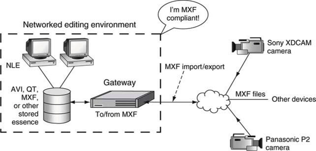
There is a world of difference between MXF compliancy and MXF compatibility. The system of Figure 7.11 is MXF import/export compliant, but it may not be MXF compatible. If it meets all the legal MXF specs—how it is formed—then it is compliant. However, in a two-sided transaction, both parties need to agree on exactly what will be transferred for compatibility. Assume that an external source has an MXF file that is OP-3a formatted, MPEG4 IBP essence with no index tables. If an internal location supports only OP-1a, MPEG2 with an index table, then there is a conflict. From the standpoint of the internal site, the external MXF file is not compatible even if it is compliant.
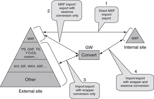
Figure 7.12 shows a stack of possible external formats, and MXF as the preferred internal format. The pyramid relates to the relative number of files in production today with MXF at the top because it is rare. A gateway (GW) sits between the external source/sink of files and the internal source/sink. The purpose of the GW is to massage the files and make them MXF compliant and compatible for import/export. Legacy files will always be with us, so the gateway is legacy’s friend.
FIGURE 7.12 File conversion gateway operations.
7.2.2.1 The File Conversion Gateway
The more choices MXF allows for (and there are plenty), the less likely that any two-party transaction will succeed without some format manipulation. The gateway performs at least four different kinds of operations per Figure 7.12:
• Case 1. MXF import/export is compatible and compliant to both sides. In this case the GW does no format changes. This is the trivial case.
• Case 2. MXF is compliant on both sides, but the MXF essence layers are not compatible. For example, the GW may need to transcode from MPEG to DV. Another possible change is from OP-3a to OP-1a. This step may cause quality degradation and delay the transfer due to slow transcoding.
• Case 3. The external wrapper is not MXF compliant (may be AVI), but the essence, say DV, is compatible. The GW unwraps the DV and rewraps it under MXF. This is a fast transaction, with no quality loss, but metadata may be lost when going from MXF to a non-MXF format.
• Case 4. The external wrapper layer is not MXF compliant, and the essence layer is not compatible. This is the worst case and costs in quality and time. Avoid if possible.
Several vendors are providing all-purpose file gateways, among them Anystream, Front Porch Digital, Masstech Group, and Telestream. Each of these vendors either offers MXF conversion or has plans to do so.
In general, gateway operations are governed by the following principles:
• Speed of file conversion;
• Transparent RT is ideal, but few gateways operate in RT for all operations.
• No or minimal loss of essence quality during conversion;
• As an example, transcoding a DV/25 file to MPEG2 at 10 Mbps will cause a generation loss of quality
• No or minimal loss of non A/V information;
• Often some metadata is deliberately left on the floor during the conversion.
• Conversion robustness;
• Testing all the conversion combinations is often not practical. For example, cross-conversion support among only 10 file format types leads to 90 conversion pairs that need to be tested and supported.
Gateways are a fact of life, but careful planning can reduce their heavy usage. With the advent of MXF, our industry will standardize on one wrapper format. Another use of a gateway is to create a proxy file from a higher resolution file. For example, a gateway (really a conversion engine for this example) can watch a file folder for signs of any new files. When a new file arrives, the engine can encode to, say, a WM9 file for use by browsers facility-wide. Gateways will become more sophisticated in dealing with metadata too. The field of metadata mapping between A/V formats is unplowed ground for the most part. Also, Moore’s law is on the side of the transcoding gateway as it becomes faster each year.
7.2.2.2 You Only Get What You Define
Okay, so you have decided all your time-based media will be MXF. If you want to reach this goal, it is best to publish an import/export specification to set the format ground rules. With adherence to these guidelines, format compatibility is all but guaranteed. Unfortunately, some suppliers will still provide MXF files that differ somewhat from what is desired. In many cases the imported file will be compatible. In other cases a gateway is needed to force compatibility. Some of the MXF specs that should be nailed down are as follows:
• SD and HD resolutions, 4 × 3 or 16 × 9, 4:2:2, 4:2:0, duration
• Video essence layer—MPEG format and type (IBP or I-only), DV, other
• Video essence compression rate (e.g., <=50 Mbps)
• Audio essence layer—AES/EBU, Bwave, other, number of channels
• Operational patterns—OP-1a and OP-ATOM will be the most common for many years to come
• Use of metadata—DMS-1 (SMPTE 380M), other, or none
• Streamable or not—MXF streams are not in common use
• Frame-based edit units or other segmentation
• Advanced topics: length of partitions, alignment of internal fields, index table location(s), VBI carriage, other
Early success with MXF depends on sticking to a formula for MXF file parameters. Without an interoperability document, MXF interchange quickly becomes a bad dream. See too the work that AMWA.TV is doing to specify an MXF Program Delivery specification (AS-03).
7.3 ADVANCED AUTHORING FORMAT (AAF)2
AAF is a specialized metadata file format designed for use in the postproduction of A/V content. Imagine a project where three different people collaborate on the same material. One person does the video edits, another does the audio edits and mix, and a third does the graphics. They all need to see the work of the others at different stages of the development. Figure 7.13 shows a typical workflow for such a production. The following is a list of common operations used in post workflows:
FIGURE 7.13 Workflow to create typical A/V program material.
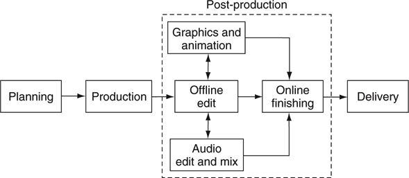
• Editing materials
• Visual effects
• Compositing
• Animations
• Mixing audio
• Audio effects
• Captions
It is obvious that a common language for material interchange is needed. At the essence level, MXF meets the need, but what is the best way to describe the assembly of the material? How are all the edits, mixes, compositions, effects, captions, and so on assembled to create the final program? This is where AAF comes in. At the most basic level, AAF is categorized as an edit decision list (EDL) format. Because it is a record of every edit operation, an EDL plus the essence completely defines the media project at any stage of development. Many proprietary EDLs exist with little interoperability and limited feature sets. There is a need for an open, extensible, full-featured “super EDL,” and AAF meets these needs.
AAF was developed as a response to the SMPTE/EBU Task Force’s recommendations for such a format. In time, the AAF Association (rebranded as the Advanced Media Workflow Association, AMWA) took up the mantle to manage AAF’s development as an open format although technically not a standard. The Association also promotes AAF through a series of awareness events.
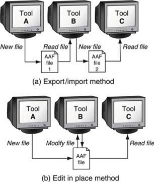
7.3.1 Methods of AAF File Interchange
AAF supports two methods to interchange edit information between assembly tools. These are the import/export and the edit-in-place models. Figure 7.14 shows the two methods. With the import/export method (top of Figure 7.14), tool A creates a new AAF file that is read by tool B. Tool B creates a new AAF file that is read by tool C. The two interchanges are independent. This model is appropriate for simple exchanges between two tools but has limitations for moving data among multiple tools. However, the edit-in-place method allows for any tool to read/modify a common AAF file as needed. Any data created by tool A can be read by tool C with no dependence on tool B. When AAF files are created or modified, a record of each application’s operations is made to leave an audit trail.
FIGURE 7.14 AAF export/import and in-place-edit interchange methods.
AAF supports internal or external A/V essence. Internal essence is practical for small projects. For larger ones, keeping the essence external (e.g., MXF) is desired. This is especially true if there are many essence files. Loading all essence into a single AAF file could easily create an impenetrable 50 GB file for just a few hours of raw video essence.
7.3.2 AAF Reference Implementation
The AMWA provides an open source software reference implementation of the AAF specification (the AAF SDK). It is distributed as C++ open source code with ports to several computer platforms. The reference implementation is recommended for use in products to reduce compatibility problems when crossing between different vendor implementations.
MXF and AAF share some common technology. MXF reuses a subset of the AAF object specification but maps it differently using KLV (SMPTE 336M) encoding. Parts of the object specification dealing with clips and source material are reused in MXF; parts dealing with compositions and effects are removed. When a common data model is used, metadata in an MXF file are directly compatible with AAF. This allows AAF and MXF to work in harmony across a broad range of applications.
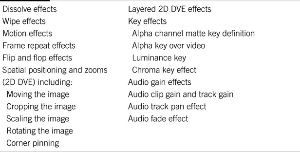
There are virtually no limits to the types of effects that a composition may contain. Vendor A may offer a super 3D whiz bang effect that vendor B does not support. In this case, how does AAF help because the effect cannot be interchanged? While it is true that not every possible effect is transportable between tools, AAF supports a subset of effects that meets the needs of most creative workflows. The AAF edit protocol defines this practical subset.
The edit protocol is designed to codify best practices for the storage and exchange of AAF files (McDermid). It constrains the more general AAF to a subset of all possible operations to guarantee a predictable level of interoperability between tools. One area that requires constraint is effects. Interchanging effects is one of the most challenging aspects of AAF. Table 7.1 shows the classes of defined effects supported by the edit protocol. Other effects will need to be rendered into a video format before interchange. In the end, AAF is a life saver for program production across a collaborative group. AAF levels the playing field and gives users an opportunity to choose their tools and not be locked into one vendor’s products.
Table 7.1 Constrained Effects: Defined for Interoperability Using AAF
7.4 XML AND METADATA
eXtensible Markup Language (XML) has become the lingua franca of the metadata world. When XML became a standard in 1998, it ushered in a new paradigm for distributed computing. Despite its hype, XML is simply a meta language—a language for describing other languages. For the first time, XML enabled a standard way to format a description language. Its use is evident in business systems worldwide, including AV/IT systems. XML makes it possible for users to interchange information (metadata, labels, values, etc.) using a standard method to encode the contents. It is not a language in the sense of, say, C+ or Java but rather one to describe and enumerate information. Let us consider an example to get things started.
Your vacation to London is over. You took plenty of video footage and now it is time to describe the various scenes using textural descriptions (descriptive metadata: who, what, when, and where). When you use XML, it may look like the following:
<other XML header code here ….>
<vacation_video>
<location> London, August, 2009 </location>
<scenes>
<time_code> 1:05:00:00 </time_code>
<action> “arriving at our South Kensington hotel” </action>
<action> “strolling down Pond St in Chelsea” </action>
<action> “walking along the King’s Road with Squeak and Dave” </action>
</scenes>
<scenes>
<time_code> 1:10:12:20 </time_code>
<action> “visiting the Tate Modern Museum” </action> <action> … and so on …
</scenes>
</vacation_video>
<other XML footer code here …>
The syntax is obvious. All the information is easily contained in a small file, e.g., London-text.xml. Importantly, XML is human readable. The labels may take on many forms, and these are preferably standardized. Several groups have standardized the label fields (<scenes>), as described later. For example, one of the early standards (not A/V specific) is called the Dublin Core. The Dublin Core Metadata Initiative (DCMI) is an organization dedicated to promoting the widespread adoption of interoperable metadata standards and developing specialized metadata vocabularies for describing resources that enable more intelligent information discovery systems (www.dublincore.org).
Due to the popularity of XML, there are tools galore to author, edit, view, validate, and do other operations.3 Because editors and producers do not want to be burdened with the details of XML, the A/V industry is slowly creating high-level applications (authoring, querying, browsing) that use XML under the hood.
Querying metadata is a very common operation. Let us assume a collection of 10,000 XML files each describing associated A/V essence files. What is the best way to query metadata to find a particular scene of video among all the essence? One customary method is to extract all metadata and load into a SQL database. A database query is supported by a variety of tools and is mature. Is it possible to query the 10K files directly without needing a SQL database? Yes, and one tool to assist is XQuery.
XQuery is a query language specification developed by the World Wide Web Consortium (W3C) that is designed to query collections of XML data or even files that have only some XML data. XQuery makes possible the exciting prospect of a single query that searches across an incoming A/V metadata file in native XML format, an archive of catalog data also in native XML format, and archived metadata held in a relational database. It will take some time for the A/V industry to appreciate the value of this important new query language.
Many professional video products offer some fashion of XML import/export. Descriptive metadata is the lifeblood of A/V production for documenting and finding materials. Expect XML and its associated metadata to touch every aspect of A/V workflow. From acquisition to ingest/logging, editing, browsing, archiving, and publishing, metadata is a key to managing media. Several industry players are defining how to use XML schemas to package metadata. The next section outlines some current efforts.
7.4.1 Metadata Standards and Schemas for A/V
We are at the cusp of standardized metadata that crosses tool and system boundaries. MXF supports SMPTE 380M for metadata descriptions. Also SMPTE supports the Metadata Dictionary, RP210. This is an extensible dictionary that may be augmented by public registry. SMPTE is also crafting XML versions of MXF metadata. In addition, the A/V industry has developed several metadata frameworks, each with its own strength.
The BBC has defined a Standard Media Exchange Framework (SMEF) to support and enable media asset management as an end-to-end process across its business areas, from production to delivery to the home. The SMEF Data Model (SMEF-DM) provides a set of definitions for the information required in production, distribution, and management of media assets, currently expressed as a data dictionary and set of entity relationship diagrams.
The EBU (www.ebu.ch) project group, P/META, defines and represents the information requirements for the exchange of program content between the high-level business functions of EBU members: production, delivery, broadcast, and archive. The P/META scheme provides defined metadata to support the identification, description, discovery, and use of essence in business-to-business (B2B) transactions. Their work effort is based on an extension of SMEF.
MPEG7 is an established metadata standard for classifying various types of multimedia information. Despite its name, MPEG7 is not an A/V encoding standard such as MPEG4. MPEG7 is formally called a “Multimedia Content Description Interface.” For an overview of MPEG-7 technologies, see (Hasegawa 2004). The standard supports a wide range of metadata features from video characteristics such as shape, size, color, and audio attributes such as tempo, mood, and key to descriptive elements such as who, what, when, and where. MPEG7 has found little use in professional A/V production so far. However, it has found application by the TV-Anytime Forum (personal video recorder products). Their defined metadata specification and XML schema are based on MPEG7’s description definition language and its description schemas.
Finally, the Institut für Rundfunktechnik (IRT) in Munich and MOG Solutions (www.mog-solutions.com) have codeveloped an XML mapping of the MXF metadata structures (DMS-1). The IRT has also developed an A/V metadata framework specific to A/V production applications. These are not yet standardized solutions but will likely find applications in some quarters.
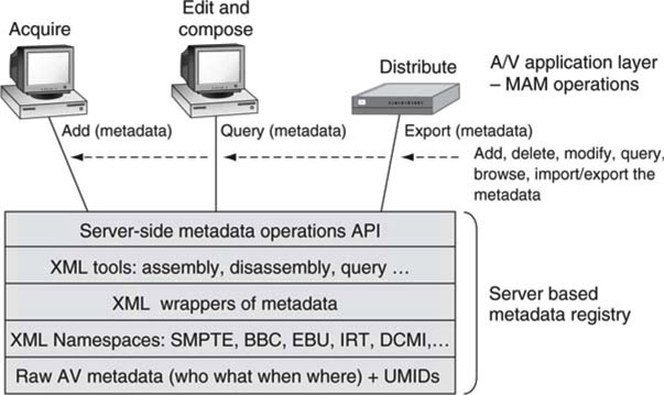
7.4.2 The UMID
Without a way to identify metadata types and essence files explicitly, they quickly become lost in a sea of data. The Unique Material Identifier (UMID, SMPTE 330M and RP 205) is a global way to identify A/V materials. It is the kingpin in the quest for a universal way to unambiguously tag every piece of essence and metadata. UMIDs identify every component part of a program and provide a linkage between the essence and its associated metadata. The UMID is a 32-byte (64 in extended form) field with the potential to identify every A/V file with a granularity of frames if desired. For example, the UMID hex value of #A214F07C could represent the unique A/V essence of NASA’s original video of Neil Armstrong’s first step on the moon. MXF relies on UMIDs for content ID. Some of its characteristics are
• It is a globally unique identifier.
• It identifies any level of material granularity, from a single frame to a completed final package.
• It can be automatically and locally issued, which means that access to a central database or a registration authority is not needed.
• It may be used in different applications, i.e., not only as a global material identifier, but also as a local identifier with some specific local applications.
Figure 7.15 puts all the concepts together in a metadata registry example. It is server based, stores XML metadata, and provides for common client metadata operations. The different layers describe functions and aspects needed to implement a searchable metadata repository. There are no standardized and commercially available metadata application servers on the market. Each vendor offers something unique and fine-tuned for its products and supported workflows.
FIGURE 7.15 XML-centric metadata registry: Server based.
Metadata management solutions range from hand-searched lists to federated networked systems with millions of metadata entries. No one architecture, schema, or vendor solution has won the hearts of all A/V users. Time will tell how metadata management solutions will pan out and what schema(s) becomes the king of the hill. Admittedly, several may rise to the top, as there is room for specialized schemas across the range of A/V businesses.
7.4.3 ISAN and V-ISAN Content ID Tags
The ISO has standardized the International Standard Audiovisual Number (ISAN) as a 64-bit value to identify a piece of programming. The ISAN goes beyond the UMID by providing fields for owner ID, content ID, and episode number. It should be embedded into the material (a watermark is one way) so that the ISAN value and content it points to are inseparable. Think of the ISAN value as representing a collection of A/V objects that are in total a program. V-ISAN is a 96-bit version that includes the version number, indicating language, edited for TV rating, and subtitles.
Metadata and their associated tools are only small cogs in the big wheel of media asset management (MAM). In what way is MAM part of the AV/IT revolution? Let us see.
7.4.4 ISCI and Ad-ID Identification Codes
The Industry Standard Commercial Identifier (ISCI) code has been used to identify commercials (aka “spots”) aired worldwide. It found application by TV stations, ad agencies, video post-production houses, radio stations, and other related entities to identify commercials for airing. The ISCI system is compact, allowing only 8 bytes to identify a commercial and its owner. This 30-year-old system is no longer adequate in a world of digitally addressable media.
ISCI is being replaced by the Ad-ID (www.ad-id.org) code with 12 bytes, 4 alpha and 8 alphanumeric. The first 4-byte alpha field identifies a company (the producer), and the second 8-byte field identifies a unique spot. Ad-ID codes are computer generated through a secure, Web-accessible database. All existing ISCI prefixes are grandfathered into the Ad-ID system.
7.5 MEDIA ASSET MANAGEMENT
There is an old saying in the A/V business that goes something like this: “If you have it but can’t find it, then you don’t have it.” With a MAM solution, enabled users can—ideally—quickly and easily locate content they possess.
With the proliferation of media assets and Web pages with embedded A/V, MAM solutions are becoming commonplace in business. More generally, digital asset management (DAM) solutions (not media centric) are used to manage text documents with graphics. Think of MAM as DAM with the ability to manage time-based media. In the big picture, both MAM and DAM are content management (CM) concepts. According to a Frost & Sullivan report, the worldwide MAM market will grow to $1.37 billion in 2010 at a compound annual growth rate estimated to be 20.2 percent. The overall market includes all types of media production and delivery, including Web based.
One definition of MAM is the process of digitizing, cataloging, querying, moving, managing, repurposing, and securely delivering time-based media and still graphics. It supports the workflow of information between users for the creation of new and modified media products.
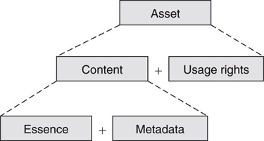
But what is a media asset? On the surface, any media that sit in company storage may be considered an asset, but this is far from the truth in practice. Figure 7.16 shows the asset equation: an asset is the content plus the rights to use it. Many broadcasters have shelves full of videos that they cannot legally play to air because the use contract has expired. Also, the content is the essence plus the metadata that describe it. In the end, both metadata and rights are needed to fully qualify and manage a media asset. In fact, we need to modify the opening quote to reflect the true reality: “If you have it and can find it but with no rights to it, then you don’t have it.”
FIGURE 7.16 The asset equation.
Rights management is a complex topic. It involves aspects of copyright law, contracts, payments, and windows of use and reuse. A single program may have sequences each with its own rights clauses. Rights age, so what is legal today may not be tomorrow. All aspects of production require knowledge of media rights. See Section 7.5.3 for a primer on DRM.
7.5.1 The MAM Landscape
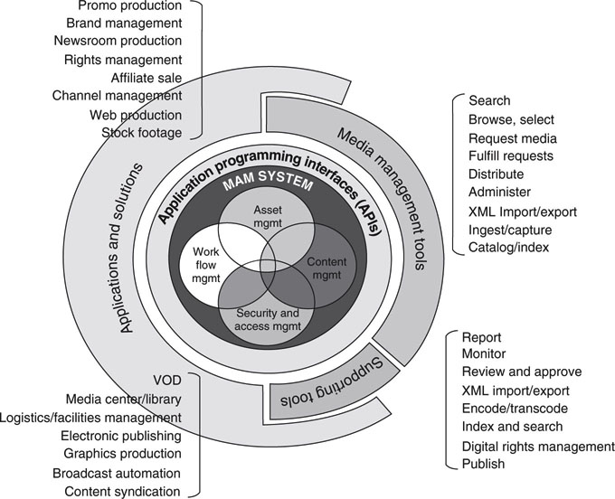
This section examines the major components in a MAM solution. Figure 7.17 outlines the MAM onion. The outer layer represents the applications and solutions needed by business processes. A/V-related ones are
FIGURE 7.17 The MAM onion.
Source: Perspective media group.
• A/V production
• Broadcast automation
• News production
• Web production
• Rights management
• Video on demand
• Graphics production
• Content syndication
Each of these application areas may require a full-featured MAM system. The next layer comprises tools for ingesting, browsing, querying, and so on. Applications make use of these features as needed. Augmenting user functions are the support tools for reporting, reviewing/approving, publishing, and so on. Applications and tools are connected to the center of the diagram using defined APIs. Finally, in the center are the core processes as listed. One area not yet discussed so far is workflow management. This is a relatively new frontier for A/V production and provides methods to manage an entire project from concept to delivery. Workflow methods are examined later in the chapter.
No doubt, full-featured MAM solutions are complex. It is very unlikely that a shrink-wrapped MAM solution will meet the needs of any large real-world business.4 Open market MAM solutions rely on customization to meet existing business process needs. Also, there are many vendor-specific aspects of these systems from video proxy formats (MPEG1, WM9/VC1, VC-3 for HD, MPEG4, etc.) to metadata formats (DCMI, SMEF, IRT, SMPTE, custom, etc.) to the APIs and middleware that connect all the pieces together. See (Cordeiro 2004) for insights into a unified API for MAM. Ideally, the MAM system should fit like a glove with the existing A/V systems architecture with its formats, workflows, control, and applications use. Unfortunately, the rather liberal use of “standard” formats prevents MAM systems from interoperating at even the most basic levels. Upgrading a MAM system from vendor A to B is a painful and often impossible task, so choose your MAM system wisely because you will live with it for a long, long time.
Choosing a commercial MAM system for a legacy business requires a large dose of compromise and realignment of internal processes to the abilities and functions of the MAM system. Many media operations have developed totally custom solutions because open market ones were not sufficient. Of course, when you are developing a new complex workflow from scratch, it is wise to base it on available MAM functionalities to enable the use of open market solutions.
7.5.2 MAM Functions and Examples
To fulfill the needs of a full-featured MAM system, the following functions (Abunu 2004) are required:
• One-time media capture and indexing of metadata (including rights, program information, usage, etc.) made accessible to all workflow participants.
• Standards for media assets for interoperability across the workflows.
• Implementation of a metadata set to support all workflow operations.
• Search functions to identify and locate A/V essence. This may range from a simple file name search to a query based on people, places, things, and activities.
• Shared views and access to media across an organization mediated by access control.
• Media life cycle management—from ingest to composing to converting to archiving.
• Workflow process support—assignments, approvals, releases, ownerships, usage history.
• Functionalities to package and distribute media according to business needs.
Exploring the intricacies of these items is beyond the scope of this book. However, to learn more about the details of MAM functionality (with support for time-based media and focus on broadcast and A/V production), study the representational offerings from companies such as Artesia Technologies, Avid Technology, Blue Order, Harris Broadcast, IBM (Content Manager), Microsoft (Interactive Media Manager), Omnibus, and Thomson. Although not media focused, Drupal (http://drupal.org) is a popular free software package that allows an individual or a community of users to easily publish, manage, and organize a wide variety of content for Web sites.
A classic case of integrating a MAM with A/V editing gear occurs in broadcast TV news production systems. Today many media companies from a large CNN to a small local TV station rely on IT-based news production systems for day-to-day operations. For example, Avid, Thomson/GVG, Harris, Quantel, and Sony all offer a range of IT-based news production systems incorporating a restricted MAM. These systems support end-to-end unified workflows from ingest to play-to-air of news stories. Metadata management plays a big role in these systems. Most of the traditional automation vendors also offer MAM as part of their overall product portfolio. It is paramount that the metadata and their format generated at video capture be usable throughout the workflow chain.
7.5.2.1 Example of an Index/MAM Query Operation
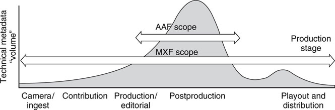
This section examines the indexing and querying operations. These are two common operators in any MAM system. Indexed and cataloged metadata are the lifeblood of any asset tracking system. Figure 7.18 illustrates the relative volume of metadata versus positions in the media workflow. As a project develops, the metadata volume increases to a peak during the editing and compositing stage. Little metadata are produced or consumed at either end of the production cycle. However, this trend may change as metadata methods become more mature. In the future it is likely that more descriptive information will be produced at image capture time.
FIGURE 7.18 Volume of technical metadata associated with a clip during production.
Source: File interchange handbook, Chapter 5.
Human entry is often the most accurate and certainly the most detailed. It is also expensive and time-consuming. Ideally, an automatic indexer will identify some of the more common elements of a scene as outlined in Figure 7.19. It will be a long time before a machine can describe the subtle interaction among four people playing poker. Still, indexing technology is steadily improving and already generates a good deal of searchable metadata.
FIGURE 7.19 A/V media indexing hierarchy.
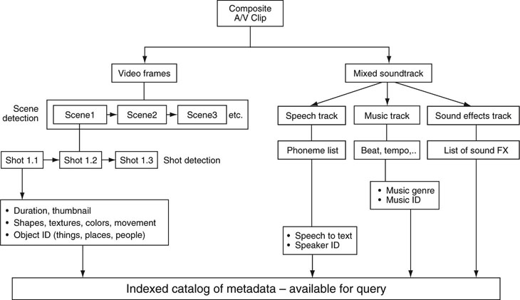
Figure 7.19 provides a divide-and-conquer approach to indexing an A/V clip. Some of the operations are straightforward and mature, such as shot detection, whereas others are state of the art, like speech to text in the presence of music. In the realm of science fiction is face recognition in a dense crowd. For less demanding scenes, such as TV news anchor ID, it is practical today. For each element there is a defined metadata type. The more powerful the indexer, the more valuable the searchable metadata. A/V indexing is a hot area of university research.
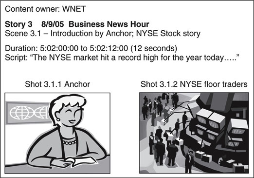
An example of a query response is illustrated in Figure 7.20. In this case the query was “Find: NYSE stock news, market high.” Assuming the required metadata exist in a catalog, then the response is formatted as shown. Because there are no standards for query method or response format, these will remain custom methods for years to come, although an XML-formatted response would make sense. Once the material is located and the access rights determined, then it may be incorporated into a project.
FIGURE 7.20 Typical query response to: “Find: NYSE stock news, market high.”
7.5.3 Using DRM as Part of a MAM Solution
Digital rights management (DRM) is a double-edged sword. Content providers claim they need it to protect their files from illegal use. However, content consumers often find DRM a royal pain, and it limits their legitimate use of the files. Although not currently used in bulk for professional applications, DRM has a place in the broadcast and A/V workflow. Today, for the most part, contracts or custom solutions are used to define rights usage at the production level. However, traditional contracts tend not to be machine friendly, whereas DRM technology is machine friendly.
The following are common features of a DRM-protected file:
• Encrypted file content—Only users with an owner-provided key can open the media file.
• Rights use—Time windows, platforms (desktop, mobile, etc.), number of viewings, copyrights, sharing rights, and so on.
• License granting—Provided with file, on-demand, or silent background methods to obtain the license/key to use a file(s).
Think of DRM as a workflow element, not just a file use enforcer. A total DRM environment includes contract authoring, file encrypting, license and key distribution, and runtime contract enforcing. So why use it in the professional domain? If you cannot afford to lose control of your distributed media, then consider DRM as one way to manage it. A compromise to a full-featured DRM is to use only file encryption and manual key transfer. This achieves a level of protection without all of DRM’s features.
One promising technology is from the Open Digital Rights Language initiative (http://odrl.net). This group has developed a rights expression language for general use, and it may find application in professional production MAM systems.
7.5.4 Tastes Like Chicken
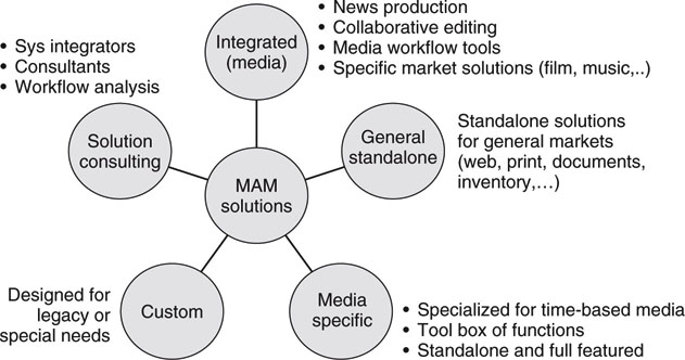
The single most important factor in leveraging all things digital is smooth, efficient workflow. Nearly every component in a well-designed project workflow has the MAM stamp on it. MAM functionality is the glue that ties all the pieces together. Figure 7.21 outlines the various classes of MAM products, tools, and solution providers. There is no such thing as a one-size-fits-all product or solution.
FIGURE 7.21 The MAM product and solution landscape.
When specifying MAM functionality for a project, think holistically. MAM should not be some add-on, plug-in, or attachment, but rather its presence should be felt systemically at all levels of the design. Imagine MAM as a personality feature of a well-designed workflow. For new designs, MAM functionality should be spelled out as part of the overall workflow, not only on a per component basis. Be specific as to what formats, operations, scale, and UI functionality are needed. Especially give care to the total interoperability among the various components. Also, be a realist. Your idea of the ideal workflow will not necessarily map into what is available commercially. It is often smarter to evaluate what is available and then pattern your workflow accordingly. Workflows also deserve mention at this point, so let us consider some of these aspects.
7.6 THE FUNDAMENTAL ELEMENTS OF MEDIA WORKFLOWS
Workflows are found everywhere in life: cooking a meal, washing a car, planting a rose bush, producing a Hollywood movie. Basically, workflow is defined as “a set of sequential steps needed to complete a job.” Some workflows are easy to implement, needing only a few tools, whereas others demand mountains of infrastructure and human capital. This section concentrates on workflows for media systems from the small edit shop producing wedding videos to a large studio creating movies.
Figure 7.22 shows the five domains or precincts of interest for media workflows. The central box represents the actual workflow steps; do this, now do that, and so on. The other four domains help define the “what and how” of workflow functionality. Some of these are common to all workflows, such as operational elements (step design, timing, tool needs, resource availability, review, etc.), whereas others are specific to media systems such as A/V streams and file-related processes.
FIGURE 7.22 The essential elements of media workflows.
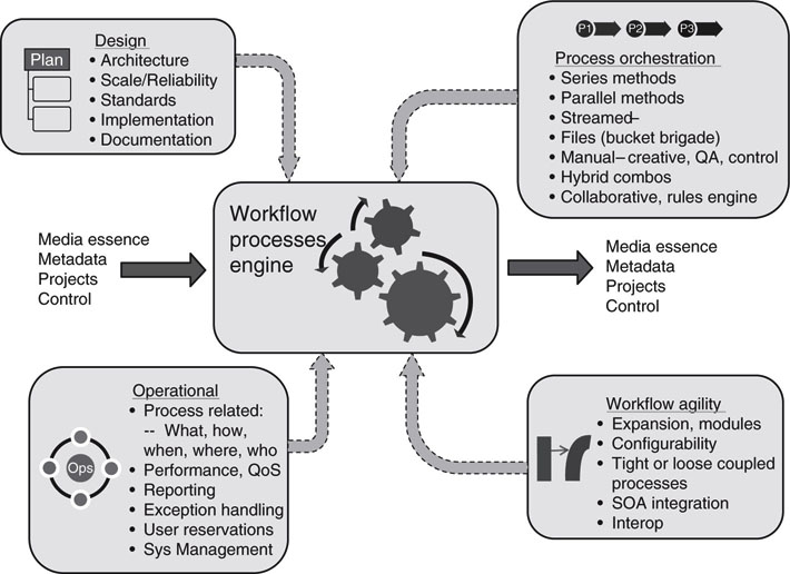
Next, let’s examine each of the elements in Figure 7.22: design, process orchestration, operational, and workflow agility. The constituent elements of these will be explored with examples. The end goal is to provide a simple high-level checklist to refer to when you are building a new workflow or modifying an existing one. For sure, this coverage is not exhaustive. Not every aspect will be examined; don’t expect to become an expert. However, you will be versed in the language and concepts of media flows and their design.
7.6.1 The Design Element
Any viable workflow needs a design stage. The key elements of interest to us are as follows:
• Architecture—What solution space do you need?
• Reliability/Scale—14 methods for building reliable systems.
• Standards and Interoperability—SMPTE, IETF, IEEE, ITU-T, W3C, AMWA, and so on.
• Implementation—Choice of vendors, systems integrator, support.
• Documentation—Workflow design, not just wiring and layout!
The famed Chicago skyscraper architect Louis Sullivan said, “Form follows function.” This simple yet powerful axiom applies to media workflows as well as skyscraper design. In essence, define your workspace and design to it. For our case, allow for growth, support agility, high availability as budget permits, and document not only layout/wiring but flows too. Figure 7.23 shows a typical generic flow for program production. This could be modified for broadcast, live event production, news, digital intermediates (DIs), or any number of flows.
FIGURE 7.23 Generic program creation process flow.
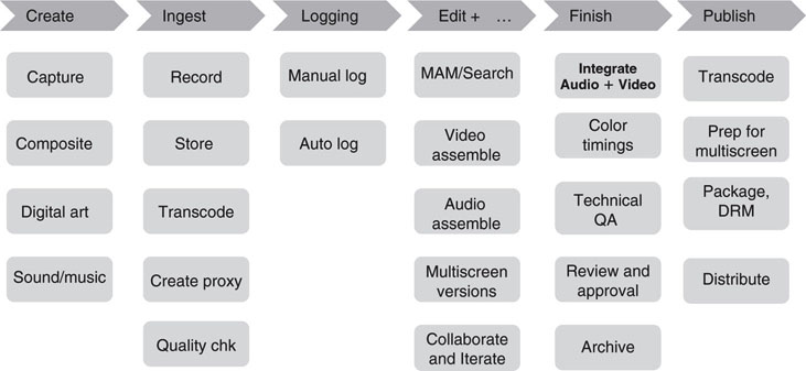
This figure may be the first step in defining the workspace for a new project. The level of detail is intentionally high. The design architecture will support these functions at a minimum. As the designer applies the divide-and-conquer rule, each process is implemented with the end goals in mind of one unified infrastructure, not islands of operations. Any given process may connect to central storage, application servers, a LAN/WAN, or traditional A/V router.
7.6.1.1 Designing for Reliability
Let’s consider the aspect of designing for reliability, the second point in the earlier list. Given the acceptable downtime, a designer may select the options outlined in Chapter 5 covering the salient aspects of building an infrastructure for high availability (HA). For the ultimate doomsday, bulletproof system, up to 14 HA techniques (outlined in Chapter 5) could be applied at once. This is hardly practical, but some real-world, mission-critical systems come close. Normally, a few methods are applied and are determined by business needs for the most part.
Every design should have a service availability goal as a percentage of uptime. For example, 99.9999 percent uptime or ~32 seconds per year of downtime could be a goal. This value is achievable and allows for one (or more) serious failure(s) with 32 seconds available (or less) to route around the failed element. Another approach is to decide what length of time a system can afford to be down (“off air ”) and design from that value.
7.6.1.2 Standards Ubiquity
No practical system should be constructed without applying standards from a broad range of sources. Gone are the days when SMPTE standards were the only glue needed to create a video system. Today, in addition, we need the standards from IETF (Internet protocols related), W3C (XML, HTML, Web services, etc.), and the IEEE (Ethernet and real-time versions), plus others. User groups such as the Advanced Media Workflow Association (www.amwa.tv) have a mission to create best practices and recommended technologies for implementing workflows in networked media environments. They are currently developing specifications for the Advanced Authoring Format (AAF), a MXF component inventory method, and a constrained MXF version for program delivery to broadcasters.
Another aspect related to standards is the selection of video formats for ingest, proxy, editing/compositing, distribution, and archive. A common case is that ingest, editing, and archive formats are all identical, with distribution almost certainly being different.
Finally, there is the need for common metadata formats across the work-flow. This goal is not easy to achieve, and not all vendors support the same metadata formats and interpretations of their meaning. SMPTE is still grappling with defining the lingua franca for an industry-accepted metadata set. It has made good progress in defining the RP210 metadata dictionary (a glossary of terms), but more is needed. For example, some groups want a constrained, small set of media metadata (the equivalent of the famous Dublin Core for library use), whereas others want a much larger accepted set. Both groups have valid concerns and business needs. If all goes well, both constituencies will have their needs meet.
7.6.1.3 Workflow Documentation Methods
Finally, under the design banner, let’s consider documentation. For many years facility documentation was a collection of diagrams showing equipment layout and racking with detailed wiring and inventory diagrams using tools such as VidCAD. This level of documentation is still necessary but not sufficient to describe the workflow component of an installation. True, not every install will require a workflow diagram, but many will. If the workflow is complex with disparate processes and time-related dependencies, then the following methods should be of value.
Workflow stakeholders include the analysts who create and refine the processes, the technical developers responsible for implementing the processes, and the technical managers who monitor and manage the processes. Two diagramming methods are gaining acceptance to define process flow; one is based on Unified Modeling Language (UML) and another on Business Process Modeling Notation (BPMN).
The UML offers the following diagram types:
• Activity (do this, then do that if …)
• Sequence (order of operations)
• Communication (messaging methods, participants)
• Timing (timelines, due dates, schedules, time dependencies, etc.)
Which one should be used to describe a media workflow? Well, each has a special purpose, so depending on what aspects are to be communicated, the choice flexible. The activity diagram offers the most flexible layout for media workflow, but all will find usage. See www.uml.org for more information and examples. See Figure 7.24 for an example of using an activity diagram.
FIGURE 7.24 UML workflow activity diagram.
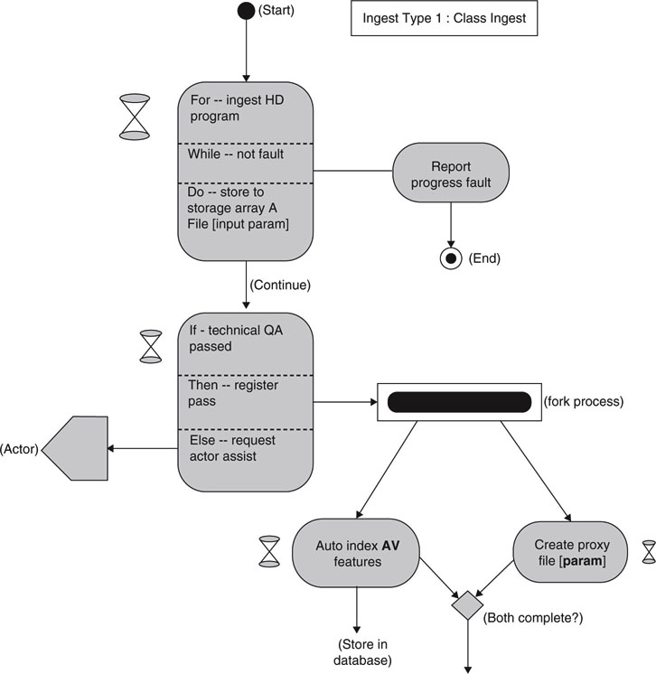
Another graphical modeling tool is Business Process Modeling Notation. Don’t be put off by the word business in the name. The tools translate to media workflows as proven by their usage by some systems integrators. The modeling in BPMN is made by simple diagrams with a small set of graphical elements. The four basic categories of elements are as follows:
• Flow Objects — Events, activities, gateways
• Connecting Objects — Sequence flow, message flow, association
• Swim-Lanes — Pool, lane
• Artifacts — Data objects, group, annotation
These four categories of elements enable designers to describe media flows. See www.bpmn.org for more information and examples.
Fortunately, there are reasonably inexpensive layout tools for both UML and BPMN. Visio and SmartDraw can author UML diagrams. Process Modeler for Visio from ITP Commerce has received excellent reviews as a BPMN authoring tool. In addition, a plethora of free tools is available for both.
7.6.2 The Process Orchestration Element
This section discusses process orchestration referred to in the upper right box of Figure 7.22. There are three primary media transfer methods using networked media techniques. They are covered in some detail in Chapter 1. In review, the methods are (1) pure file transfer, (2) real-time streaming, and (3) storage access.
These three methods are the building blocks for the modern media facility. Designers must use wisdom when selecting one method over another. A big mistake when doing a new design is to mimic a videotape workflow using networked media. Videotape flows are limited in many ways and networked media allow for many dimensions not permitted using only tape.
7.6.2.1 Comparing Flow Types
Next, let’s compare three flow types: one using pure streaming and two using file transfer. Figure 7.25 illustrates these flows.
FIGURE 7.25 Three common media flow models.
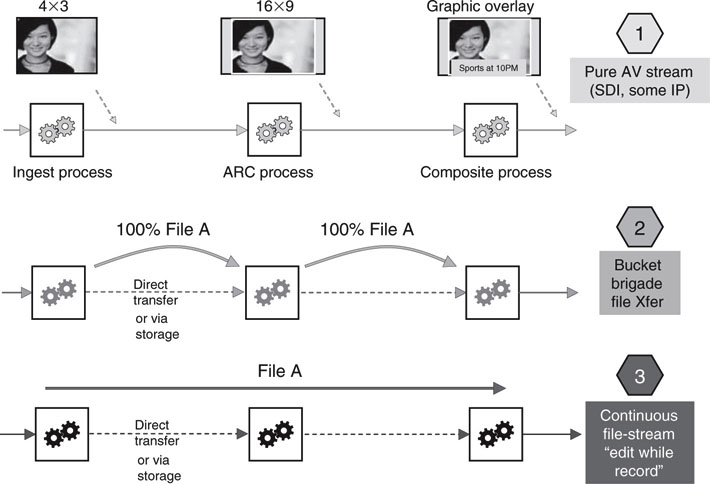
The general idea is to process an incoming video signal program as follows: ingest/record, apply an aspect ratio, convert side panels, add a lower third graphic, and finally output the result. The top flow is most commonly seen using SDI (or AES/EBU links for audio-related applications) connectivity. Of course, a process may be any transform or human-assisted means. For live events demanding a minimal in/out latency (few video frames), SDI streaming connectivity is king and used often.
The middle flow uses the bucket brigade method. First, the entire program is ingested and saved to storage. Then either by a file transfer between processes or via an intermediate “parking place” storage device, the program file is moved to the ARC process, then to the graphic composite overlay process, and then output. In each step, the entire file is imported to a process and then exported to the next process in the chain—hence, the bucket brigade nickname. The delay from in to out can be quite large, on the order of 10–20 minutes (total ARC and composite process delay) for a 60-minute program, not counting the time to ingest the incoming program (60 min). The faster each individual process, the shorter the total in/out delay. A designer would choose this method when completion delay time is not a critical metric. For example, if the completed program is needed the following day, then by all means use this flow method. When timing is not critical, then low-speed transfers and slow processes may be used. Note, too, that individual processes don’t need to work in real time, and this relaxes their design. In fact, most A/V processes can work much faster than real-time video.
The third flow is useful when the in/out delay needs to be low delay but not as short as the fully streamed flow. Basically, the target file is continuously streamed between processes. This style may be called “process-while-record,” with “edit-while-record” being a common version. So, as process #1 finishes, say, the first 30 seconds of its task, process #2 can start its task and so on. No need to wait for an entire process to complete before another process in the chain can start, as with the bucket brigade. As long as the next process does not work ahead of the succeeding process, then all is well. Process timing is critical. Edit-while-record is used with some breaking-news story production. The editor can start his or her task even while the program material is being recorded with consequent faster time to air.
These flow methods may be combined in hybrid means to form serial/parallel versions. Decision steps are needed too, so a process branch may occur. A rules engine may be of use to automatically process tasks. Look for opportunities to automate common process chains. This not only saves manpower and speeds up a process chain, but also yields metrics to improve the flow.
Flow Efficiencies
Most flows are based on moving compressed video along with uncompressed audio files and/or streams. For video, designers have a choice of pure intraframe (short GOP, I-frame only) or inter-frame (long GOP) compression formats (see Chapter 11 for more on GOPs). Building a long GOP workflow is non-trivial since it requires great attention to frame accurate editing, effects compositing, recording, and playback. So why do it?
Long GOP required storage and data rates are typically 3–4 times less compared to I-frame only formats for equivalent visual quality. So, a 150 Mbps I-only production-quality format has roughly the same visual quality as a 50 Mbps long GOP format. One issue with long GOP formats is so-called generational loss. If repeated encoding and decoding cycles of the same file are needed, then the visual signal/noise ratio will decrease with consequently more artifacts as generations increase. If many repeated compression cycles are not required then quality is maintained and the long GOP workflow is very resource efficient.
7.6.2.2 The Metric of Money
One common metric of interest to all facility managers is daily operational cost of a given process flow. If file transfer is involved between site locations, then the cost of bandwidth may be a significant factor in workflow cost. We all know the proverb “Time equals money.” There are plenty of examples of this for both long (airline flights) and short (FedEx shipping) times. In the spirit of this analogy, there is a corollary to this: 1/Time = Money. This is also true since 1/T is rate (such as Mbps), and we pay for data transfer rates. A 1 Mbps WAN link costs substantially less than a 100 Mbps link.
One beauty of working with files is that transfer speed may be selected independently from the actual real-time nature of the video content. So a 10-minute video file may be transferred in 1 minute (×10 speed up) or in real time at 10 minutes or 100 minutes (1/10 slow down), with the actual rate selected based on need. In general, choose slow transfers over fast to save cost. Conscious effort to use slow file transfers may slash the operational costs of a workflow significantly. This variable is not available for SDI streaming. Incidentally, this metric applies to storage access rates too and not just WAN transfer rates.
7.6.3 The Operational Element
This section outlines the points in the lower left box of Figure 7.22. The main aspects relate to process-related concepts: what, how, when, where, and who. Let’s use the create proxy step in Figure 7.23 as an example. When you are defining a workflow process step, it’s a good practice to define each of these five characteristics for each step:
• What are the specs for the create proxy step? Encoder type, data rates, speed, file format, invoke means, input/output means, etc.
• How will create proxy be implemented? Use Vendor X’s encoder, running on Vendor Y’s server connected to storage Main. Reliability means, failover means, scale means, monitor means, Web services means, API means, etc.
• When will create proxy be invoked? Workload, duty cycle, peak/average jobs, etc.
• Where will create proxy be located? Local instantiation, remote service, contracted service, etc.
• Who will own and manage the create proxy service (A/V operations, IT operations, contracted operations), and who will use it (number of invokers, department, etc.)?
Resolving each of these interrogatives is good practice. The process of answering each question forces a designer to think deeply about each process. This way, hidden efficiencies may be uncovered; for example, we can share server Y with other processes, since the create proxy workload is small even with 2× more loading. Or, we can locate server Y in room M, since there is ample power and cooling available.
7.6.3.1 Performance QoS, Reservations, Exceptions
Although this topic is related to the five questions in the preceding section, it’s of value to define the performance QoS, reservation methods, and error handling as separate aspects. Documenting application QoS is useful when scaling or changing a service in the future. When a service is shared (edit suite), then a reservation system with time used, billing, and resource usage may be required. Providing a systemwide reservation board (similar to a flight departure/arrival schedule display) available for all to see is often a good practice at a large facility.
Exception handling deals with HW/SW warnings, faults, errors, and status messaging. When something is out of order in one way or another, it should be registered and personnel notified to repair it. Exceptions may range from warnings of intermittent errors to out-of-spec signals (audio peaking) to resource status (90 percent full) to a complete device failure. High-end infrastructure monitoring systems are available from traditional IT vendors such as IBM, HP, CA, and others. A/V-specific solutions are available from several vendors. See, for example, the RollCall family from Snell and Wilcox and CCS Navigator from Harris.
Investing in monitoring and diagnostics products is a matter of ROI for the most part. If you are running a hobby shop, then equipment downtime may not be a big issue. If you are offering services—creative tools by-the-hour, commercial program playout—then money spent on keeping the facility up and running is worth the investment.
7.6.4 The Workflow Agility Element
The last major category is workflow agility, as shown in Figure 7.22. Agility is defined as “the ability to move in a quick and easy fashion, change directions quickly.” Typically, media workflows are purpose built: broadcast, post, animation, news, live events, DI, and so on. It’s prudent, as discussed, for form to follow function. Nonetheless, within the bounds of scale, future changes, and reconfigurations, a workflow should be agile.
When your boss asks for a new feature set on an existing system, you want to say, “No problems. Can do.” Of course, no one can economically build a system with ultimate agility that anticipates all future requests. Still, designers can prudently craft workflows that are pliant to bounded future changes.
The most common dimensions of agility are as follows:
• Expansion, scale—Grow media clients, I/O, signal routing, connect bandwidth, storage, applications, reliability, reach, power, cooling, space
• Secondary storage—Backup, archive options
• Configurability—Ease in “re-wiring” a workflow to do something different and extend its functionality and life
• Web services connectivity—Usage, metrics, performance, reliability
• Interoperability and reuse—Between system components, between other systems, between partners
• Business process interfacing—Service-Oriented Architecture (SOA) ideals. This exposes the A/V technical layer to business processes for control, messaging, monitoring, and reporting. Too, it is created using a networked services model.
Approach every design with the idea of creating a flexible engine ready to move in a new, bounded direction as needed. Plan on allocating some project budget dollars to features that enable system flexibility.
7.6.4.1 Loosely Coupled Designs
One key aspect of flexibility is the concept of loose versus tight coupled processes. Figure 7.26 illustrates this concept. Many legacy A/V systems are built on tightly coupled designs—“hard wired,” rigid systems with little flexibility for reordering or quick reuse of components. Sure, SDI and AES/EBU audio links are easily routable, but this does not constitute a loosely coupled system.
The concept of loose coupling is defined as follows:5
FIGURE 7.26 Comparing tightly and loosely coupled designs.
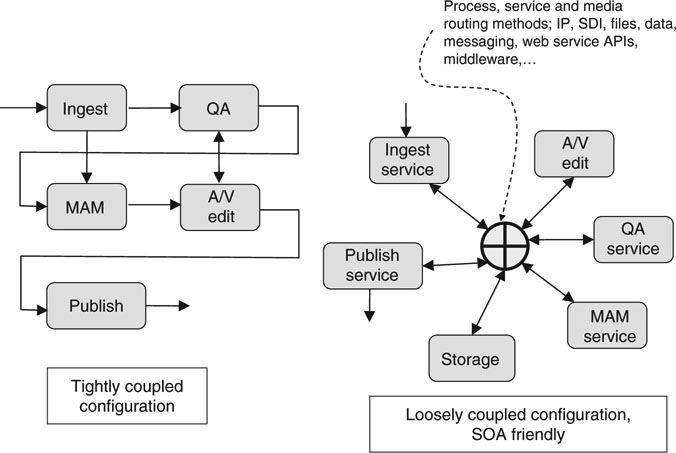
The friction-free linking enabled by web services or equivalent. Loosely coupled services, even if they use incompatible system technologies, can be joined together on demand to create composite services, or disassembled just as easily into their functional components. Participants must establish a shared semantic framework (APIs) to ensure messages retain a consistent meaning across participating services.
Loosely coupled designs rely on the aggregation of distributed services. A service is a networked application function available for use by others. Examples are video transcoders, media encoders, transfer engines, 3D render engines, a MAM searching engine, technical QA evaluation, and so on. Each function is available over a networked IP connection, is instantiated on an application server, provides a standardized access API, and defines a performance QoS for each client user.
Given a collection of relevant services, a designer can configure them to perform useful operations such as shown in Figure 7.26. These services are scalable, reliable (based on methods explained previously), reusable (the mantra of services design), and well defined in terms of API interfacing, data structures, and performance QoS.
One outstanding example of a services specification is defined by the W3C group. This group has defined what it calls Web services, and this includes specs for all aspects of interfacing to services, securing them, naming, addressing, finding, monitoring, and so on. Despite the name Web services (WS), these are not bound to the Web. They may be implemented across the Web or inside a secure enterprise environment. Google, Yahoo!, Salesforce.com, Amazon, MySpace, and many others offer Web services (or similar RESTful services) for public and private use. Some enterprise media facilities are using Web services for select applications. These topics and the concepts of SOA are discussed in more detail in Chapter 4.
Web services are not a panacea for all aspects of a media workflow. Realtime A/V operations often require dedicated devices to meet their QoS spec, and Web services fall short today. Still, when real time is not an issue, then workflows using Web services are practical and will see more light of day as our industry builds confidence in their practical value.
7.6.4.2 Workflow Platform Examples
One popular platform with Web services interfacing is the Avid Interplay Platform. This workflow engine enables MAM, media capture, proxy creation, logging, transcoding, review, simple story layout, revision, collaboration, craft editing, and more. The built-in APIs enable third parties to control select features, import/export metadata, asset deletion, register new files, spawn file transfers, and access archives.
Another example of a workflow engine is Mediaflex from TransMedia Dynamics. TMD provides a reconfigurable, modular software product suite for managing the production, delivery, archiving, and repurpose of media content in multiple formats. Its functionality can be reconfigured via a GUI to achieve agility.
The landscape is not barren. Flexible workflow solutions ranging from a “station-in-a-box” to complete news production systems are available. To learn more about this ocean of solutions, see Dalet’s DaletPlus, Thomson’s ContentShare 2, Cinegy’s Cinegy Workflow, Apple’s Final Cut Server, Pharos’s Mediator, and BitCentral’s Precis as a good representation of what is available.
7.6.4.3 Workflow Takeaways
The definition of workflow as “a set of sequential steps needed to complete a job” is deceptively trivial. Yet, behind these few words lies a world of sophistication in terms of design, planning, documentation, implementation, and operational aspects. This chapter outlines the fundamental elements of any professional media workflow. By using these concepts and maxims as a guide or checklist, architects, designers, and engineers will have added confidence in the merits of their workflow solutions.
7.7 BROADCAST AUTOMATION
Automation techniques have a long history in TV station operations. Born from the pressure to replace human operators with automated processes, automation was initially used to frame accurately control (record, shuttle, play) videotape decks. From this humble beginning, automation can now control virtually all aspects of scheduled broadcast operations. Some TV stations, especially those without live events (news), can run with lights out for the most part, with automation software running technical operations.
Automation’s role in a typical broadcast facility is as follows:
• Control A/V devices and process frames accurately;
• Video servers, tape decks, graphics/text engines, master control levels, signal routing, video transcoding, file transfer, secondary-event video compositing, recording, playout, satellite feed recording, news gathering, archiving, and more.
• Execute the provided schedule (from the traffic department) following a 24-hour timeline accurately timed to the SMPTE house clock. Every device operation may be controlled based on the common SMPTE clock. This assures all operations occur at precisely the correct frame time across all devices in a facility: queue file, play file, overlay scrolling text on video, set level, output to viewers. Log “as run” information to prove schedule execution. Incidentally, BXF plays a big role here. See Section 7.1.2.
Prompt, control, and monitor all human-assisted media prep operations.
• Ingest new materials, trim, handle QA.
• MAM support for registering new materials, metadata, searching, and indexing.
Broadcast automation is mature and supported by many vendors worldwide. Other types of automation are also popular, including news broadcast (with studio camera robotics control) with associated story production management. Virtually all aspects of automation’s functional task list can be implemented using IT-based servers, networking, and storage. This is a control plane application for the most part (Section 7.1). Workflows of all types may be automated—partially or in full—if repeated, scheduled, or template operations are implemented. Expect to see automated operations gain more ground over the next few years as facility owners demand more ROI from their infrastructure investments.
7.8 IT’S A WRAP—A FEW FINAL WORDS
In this chapter and the preceding six, we have presented the fundamentals of media systems. Building or remodeling a media facility is a tall order, and you will likely require the skills of an expert systems integrator. When selecting an SI, look for knowledge and proven track record in IT and A/V systems. Use the insights, guidelines, and best practices outlined in these chapters to assist in making wise choices, especially during the design stage of a project.
1 The term essence denotes underlying A/V data structures such as video (RGB, MPEG2, etc.), audio (AES/EBU, WAV, MP3, etc.), graphics (BMP, JPEG, etc.), and text in their base formats.
2 This section is loosely modeled after and paraphrased from parts of Chapter 6 (AAF) by Phil Tudor, File Interchange Handbook (Gilmer).
3 For more information on some key XML definitions, learn about the XML schema and namespaces as defined by the W3C at www.w3c.org/xml.
4 Shrink-wrapped MAM solutions often meet the needs for simple workflows (Web page asset management) with a small number of users.
5 See glossary at http://LooselyCoupled.com.
REFERENCES
Abunu, D., et al., The BBC in the Digital Age: Defining a Corporation Wide MAM Approach, page 417, Conference Publication of the IBC, 2004.
Bhaskaran, V., et al. (1997). Image and Video Compression Standards (2nd ed): Kluwer Press.
Cordeiro, M., et al. (September 2004). The ASSET Architecture: Integrating Media Applications and Products through a Unified API. White Plains, NY. SMPTE Motion Imaging Journal.
Gilmer, B. (Ed.). (2004). File Interchange Handbook: For Professional Images, Audio and Metadata: Focal Press.
Hasegawa, F., & Hiki, H. (2004). Content Production Technologies. Hoboken, NJ: Wiley.
Marpe, D., et al. (February 2004). Performance Evaluation of Motion-JPEG2000 in Comparison with H.264/AVC Operated in Pure Intra Coding Mode. Proceedings of SPIE, 5266, 129–137.
McDermid, E. AAF Edit Protocol: Introduction and Overview, SMPTE Motion Imaging Journal, page 225, Issue: 2004 07/08 July/August
Poynton, C. (2003). Digital Video and HDTV—Algorithms and Interfaces. San Fransisco, CA: Morgan Kaufmann.
AAF and MXF Tutorials. (2004) 07/08 July/August. SMPTE Motion Imaging Journal.
Symes, P. (October 2003). Digital Video Compression. NYC, NY: McGraw Hill/TAB.
Wiegand, T., Sullivan, G. J., Bjontegaard, G., & Luthra, A. (July 2003). Overview of the H.264/AVC Video Coding Standard. IEEE Transactions on Circuits and Systems for Video Technology.