
Chapter 10
Managing Networking for a Virtual Machine
Networking, like the circulatory system in your body, is the transport mechanism for moving vital supplies. While blood carries nutrients to the organs, computer networks traffic in information, which is just as crucial to the health and well-being of the applications in a data center. In a virtual environment, networking is a critical component of the architecture, ensuring that data arrives in a timely fashion to all of the virtual machines on a host. Much like storage I/O, network I/O is subject to the same bandwidth issues and constraints that can occur in a physical network environment. Because networks also carry storage traffic, they need to be sized, implemented, and managed properly in order to provide adequate performance to the disk storage systems as well.
- Understanding network virtualization
- Configuring VM network options
- Tuning practices for virtual networking
Understanding Network Virtualization
Even more so than data storage, networking is everywhere in our daily lives. We update our Facebook pages, send email, send text messages, and tweet with smart devices that must be connected through a network to the servers that provide these functions. Telecommunications providers charge money for data plans—and as you use more, you pay more, as you would for any utility such as water or electricity. In our cars, the GPS talks to satellites across networks that give us real-time traffic information. In newer models, our devices connect to the Internet via a Wi-Fi connection in the car. At home, our computers can be connected to a cable modem, DSL, or even a dial-up connection to access the Internet. Newer televisions and multimedia devices allow us to stream movies, on-demand content, music, and even YouTube videos from a growing list of satellite providers, cable providers, and other content providers like Netflix, Hulu.com, and Amazon.com. More and more connectivity provides access to data, and bandwidth controls the speed at which it arrives.
IT departments and data centers have been dealing with these technologies and issues for decades, and networking, though at times a complicated topic, has very well-defined models and practices to follow for good performance. Like the storage practices you learned about in the last chapter, network practices also translate very well to the virtual environment. This explanation of networking is a very basic one, good enough for this discussion of how network traffic flows through a virtual environment, but is not by any means comprehensive. At the most fundamental level, networking allows applications on a virtual machine to connect to services outside of the host on which it resides. As with other resources, the hypervisor is the manager of network traffic in and out of each virtual machine and the host. The application sends a network request to the guest operating system, which passes the request through the virtual NIC driver. The hypervisor takes the request from the network emulator and sends it through a physical NIC card out into the network. When the response arrives, it follows the reverse path back to the application. Figure 10.1 shows a simplified view of this transaction.
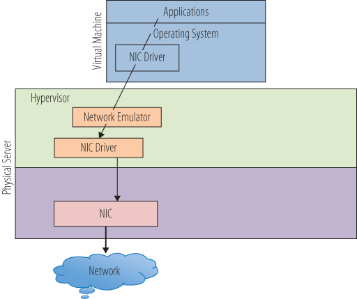
Figure 10.1 A simple virtual network path
Virtualization adds a number of wrinkles to the networking environment. One of these is that a virtual network needs to provide a method to connect to other virtual machines on the same host. In order to make this connection, the hypervisor has to have the capability to create internal networks. Just as a physical network uses a hardware switch to create a network to isolate traffic among a set of computers, a virtual switch can create a network inside a host for the virtual machines to use. The hypervisor manages the virtual switches along with managing and maintaining the virtual networks. Figure 10.2 shows a diagram of a simple virtual network inside of a VMware vSphere host. The hypervisor has two virtual switches, one connected to a physical NIC, which is connected to the outside physical network. The other virtual switch has no connections to a NIC or any physical communications port.
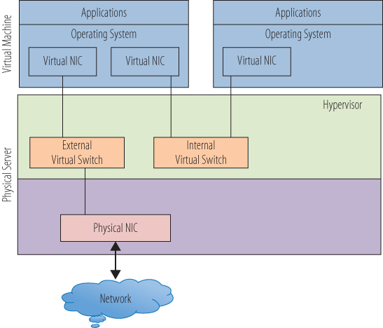
Figure 10.2 Networking in a VMware host
The virtual machine on the left has two virtual NICs, one connected to each virtual switch and by extension, each of the virtual networks. Requests through the virtual NIC connected to the external virtual switch will be passed through the physical host's physical NIC out to the physical network and the outside world. Responses to that request follow the route in reverse, through the physical NIC, through the external virtual switch, and back to the VM's virtual NIC. Requests through the internal virtual switch have no path to the outside world and can only go to other virtual machines attached to the internal virtual switch. The right-hand virtual machine can make requests only through the internal virtual switch and, in this simple diagram, can communicate only with the other virtual machine. This is a common strategy in a virtual environment to secure applications and servers from unwanted attacks. Without a connection to a physical NIC, the right-side virtual machine cannot be seen, much less compromised, from an external source. The left-side virtual machine acts as a firewall and, with reasonable security practices, protects the data contained in the other VM.
An advantage of this virtual machine to virtual machine communication utilizing an internal switch is that the traffic never leaves the physical host and takes place entirely in memory. That makes it very fast, much faster than if the data left the host and traveled the physical network, even if it were to a host that was physically adjacent to it in the data center. Very often when applications on separate virtual machines require a great deal of back-and-forth conversation, they are deployed on the same host in a virtual environment to effect the shortest network latency. Another byproduct of this internal-switch-only traffic is that standard network tools cannot see it. In a physical environment, when there are application performance issues, network tools can monitor the type and flow of data to help determine where the issue might be. In this case, the traffic never leaves the host, and standard network monitoring tools are useless because the data never hits the physical network. There are other tools specific to virtual environments to solve these problems, and we will examine them in more detail in Chapter 14, “Understanding Applications in a Virtual Machine,” in the context of performance monitoring.
In physical networks, switches are used not only to create networks but also to isolate network segments from each other. Often different functional parts of an organization require separate network spaces in which to work. Production is separate from test and development. Payroll applications are set apart from customer services. This architecture helps with performance by reducing traffic on each segment and improves security by restricting access to each area. The technique translates very nicely to virtual networking. In Figure 10.3, a second physical NIC has been added to the host. A second external virtual switch is created that is directly tied to the second NIC. A third virtual machine is added to the host, and it can communicate only to the new external virtual switch. Even though it resides on the same physical host as the other virtual machines, there is no way for it to communicate with them through an internal connection. Unless there is some possible path routed through the physical network, it cannot communicate with them externally either.
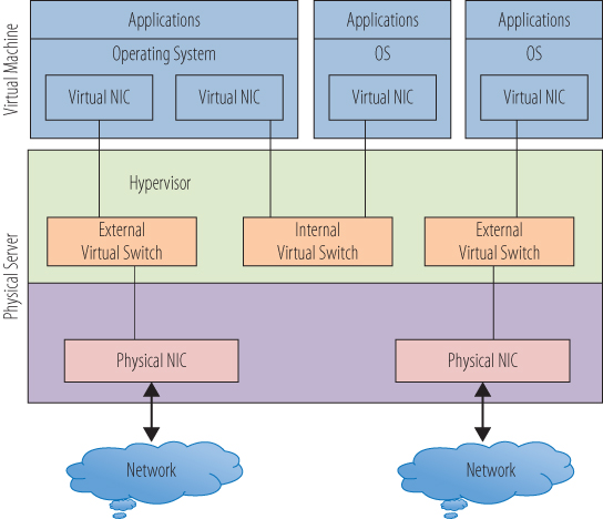
Figure 10.3 Multiple external switches
As you also saw in the previous chapter, this model is slightly different in the Xen or Microsoft Hyper-V network models. Figure 10.4 highlights the fact that all of the network traffic goes from the user (DomU) or child partitions, through Dom0 or the parent partition. In this model, the virtual switch is in the parent partition. A network request from an application in a child partition is passed through the virtual adapter to the virtual switch in the parent partition. The virtual switch connects to the physical NIC, and the request is passed to the physical network. The second switch shown has no connection to a physical NIC and supports an internal-only network. Virtual machines that connect only to this virtual switch have no way to directly access the external network. Conversely, this virtual machine can be accessed only from another virtual machine that is connected to this virtual switch, and not from an external source. Because in this model the parent partition does directly control the physical NIC, the hypervisor does not manage the network I/O.
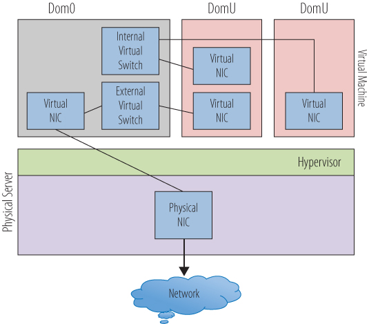
Figure 10.4 Networking in a Xen or Hyper-V host
Consider that aside from application data transport, the network may need to handle storage data. In Chapter 9, “Managing Storage for a Virtual Machine,” you saw that storage can be connected through TCP/IP-based protocols via standard Network Interface Controllers (NICs). Storage data will then traverse the same pathways, physical and virtual, that user network traffic uses. As you architect your virtual connectivity, if you utilize these protocols to access storage, you will need to plan for the appropriate amount of bandwidth and maybe even create dedicated network pathways to those devices. Figure 10.5 shows a virtual switch that is dedicated to storage I/O. Each of the virtual machines has a virtual NIC that is dedicated to storage traffic. The virtual NICs connect to the storage virtual switch. The three switch types (internal, external, and storage) are identical in their construction and operation and have been given different names here only for the sake of differentiating their functions. From the storage virtual switch, you connect to the physical NIC and then out to the network storage device. In this simple model, there is one storage virtual switch connecting to a single storage resource; but as with the network isolation you saw earlier, there can be multiple virtual switches dedicated to storage, each connected to different physical NICs that are each then connected to different storage resources. In this way, you can separate the storage resources from the virtual machines as well as the network access. Whether the virtual NICs are handling user data for the network or data from the storage devices, from inside the virtual machine, everything still looks as it would from inside a physical machine.
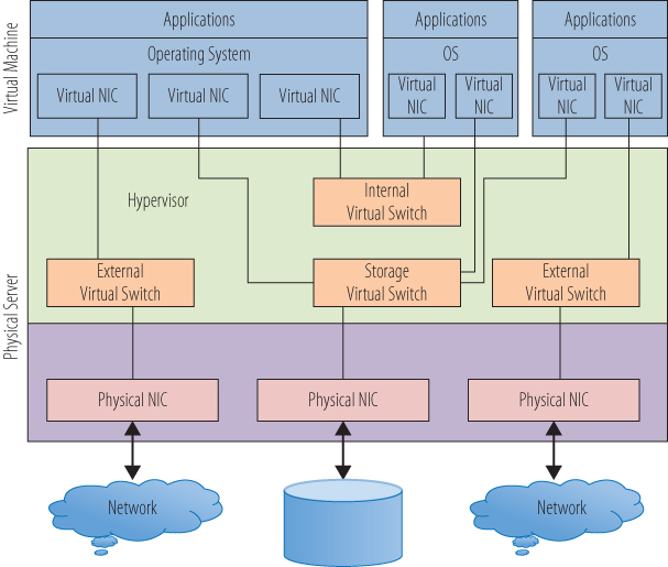
Figure 10.5 A storage virtual switch
Another facet of networking in a virtual environment to be aware of is the concept of live migration or VMotion. VMotion is VMware's term for the ability to migrate a virtual machine from one physical host to another while it is still running and without interrupting the user applications that it is servicing. The technology that allows this is essentially a rapid copy of the memory instantiation of the virtual machine to the secondary host fast enough to switch the network connections to the new virtual machine without compromising the virtual machine's data integrity or the user experience. As you might imagine, this operation is bandwidth intensive and requires a dedicated path to guarantee success. This is also a function that is handled by the hypervisor, transparent to the virtual machines. Other vendors have similar live migration capabilities, and we will cover more about them in Chapter 13, “Understanding Availability.” This is not a capability we can demonstrate using VMware Workstation Player.
Virtual switches, like their physical counterparts, can be configured to perform in selected manners. One difference is that you can adjust the number of ports on a virtual switch, without needing to replace it as you would a physical switch. Other properties that can be adjusted fall under the broad category of policies. Policies cover how the switch is to work under certain circumstances, usually dealing with security, availability, or performance-related issues. Because VMware Workstation Player does not afford us the ability to actually create and manipulate virtual switches, we will follow this thread no further.
Another networking area to briefly investigate is system addresses. Every device connected to a network has a unique address that allows the requests it makes of network resources to be returned to the correct place. Virtual machines need addresses just like any other device, and if there are multiple NICs in the configuration, the virtual machine will need an address for each one. A system address can be acquired in numerous ways. A network administrator can assign an address to a physical or virtual server, and it will be assigned for its lifetime. There are also devices that will assign an address to a device for some period of use. Dynamic Host Configuration Protocol (DHCP) is a process that allows a server to assign an IP address to a computer or other device that requests one. If you have spent any time at all setting up, or even utilizing, a Wi-Fi network, your devices are probably getting their network addresses via DHCP. The bottom line is that virtual machines need addresses. Using your Windows 10 virtual machine, you can see what address the virtual machine has been assigned.
- In the virtual machine, enter cmd into the Search text box. Select the cmd icon. When the command-line window opens, enter the command ipconfig and press Enter.
As shown in Figure 10.6, you can see your system IP address in the traditional dot and decimal format, the four octets next to the IPv4 Address label. If there were multiple NICs in this virtual machine, there would be additional entries with additional IP addresses.
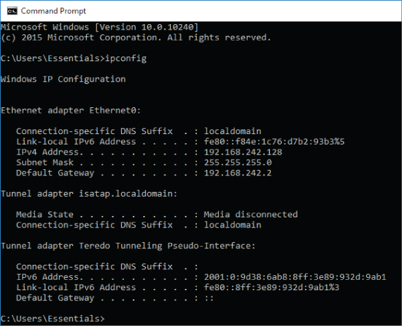
Figure 10.6 Determining an IP address
- Close the Command window.
Now let's examine the virtual NIC from a number of perspectives.
- Again, in the virtual machine, enter device into the Search text box. Select the Device Manager icon. When the Device Manager utility opens, select the triangle to the left of the Network Adapters icon to display the adapters.
- Right-click on the revealed network adapter and choose Properties. Select the Driver tab, as shown in Figure 10.7.
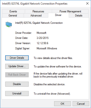
Figure 10.7 Network adapter properties in a VM
You can see a standard Intel network adapter with a standard Microsoft driver. From the virtual machine's point of view, the virtual network adapter is identical to a physical network adapter.
- Select Cancel to close the Properties window. Exit the Device Manager.
Let's examine the network adapters from the perspective of the host system.
- Not in the virtual machine, but from the host Windows operating system, enter device into the Search text box. Select the Device Manager icon. When the Device Manager utility opens, select the triangle to the left of the Network Adapters icon to display the adapters. In addition to the two physical network adapters for wired and wireless connections, two others are labeled VMware Virtual Adapters.
- Right-click on either of the VMware adapters and choose Properties. Select the Driver tab, as shown in Figure 10.8.
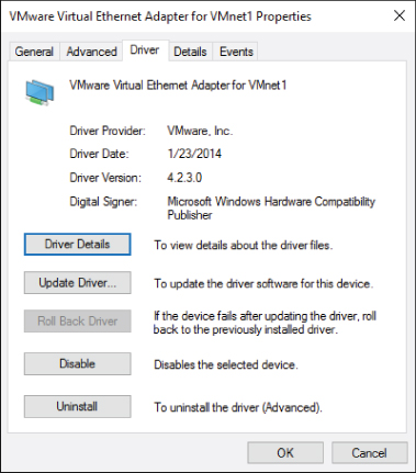
Figure 10.8 Virtual network adapter properties
You can see that this adapter is a VMware virtual adapter; in other words, it is a software construct that represents an adapter with which the virtual machines can connect. In the case of VMware Workstation Player, this virtual adapter is analogous to the virtual switches that the Type 1 hypervisors utilize. There are two different adapters here, and each has a different function, along with a third that you will see shortly.
- Select Cancel to close the Properties window. Exit the Device Manager.
Now we will examine the various connection types you can select when creating a network connection.
- Back in VMware Workstation Player, under the Player pull-down menu, from the Manage option, select Virtual Machine Settings. Highlight the network adapter. Figure 10.9 shows the network connection choices.
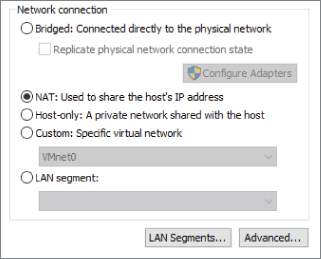
Figure 10.9 Virtual machine network-adapter connection types
We will focus on three connection types in the next section. They are bridged, NAT, and host-only.
We are going to skip LAN Segments and the Advanced features as outside of the scope of this text. LAN Segments gives you the ability to create a private network to share between virtual machines, and you can learn more by checking the user documentation.
The Custom option, as it states in the window, allows you to choose a specific virtual network. Care should be taken if you opt to use this route because certain virtual networks within VMware Workstation Player are preconfigured for certain connection types. Don't use these for a Custom network. Again, the user documentation provides the pertinent details.
- Select OK to close the Virtual Machine Settings
Configuring VM Network Options
Each of the three connection types is associated with one of the default virtual adapters on the host system. Virtual machines that are configured with a host-only network connection are tied to the VMnet1 virtual adapter. Virtual machines that are configured with a NAT connection are tied to the VMnet8 virtual adapter. Virtual machines with bridged connections are tied to the VMnet0 virtual adapter. You've seen both the VMnet1 and VMnet8 adapters, but not the VMnet0 adapter. The reason is that VMware Workstation Player exposes only a subset of its abilities through the application interface, and not all of the capabilities are accessible by default. In order to investigate virtual networking more closely, you will need to use another utility that is no longer packaged as part of VMware Workstation player.
As of Release 12, the Virtual Network Editor is no longer included as part of the Workstation Player installation package, but it is still part of the Workstation Pro installation. In order to use the utility, if you aren't using Workstation already, you will need to download and install it as an evaluation. Workstation Pro is found on the VMware site where Workstation Player was located, and the installation is almost identical. The installation can be completed using the default settings.
- Open Windows File Explorer and navigate to the directory where VMware Workstation Pro was installed. The default directory is
C:/Program Files (x86)/VMware/VMware Workstation. - Right-click the
vmnetcfg.exeentry and choose Run As Administrator to open the Virtual Network Editor. Windows will ask for permission to allow the program to execute. Choose Yes to continue. - The Virtual Network Editor opens as shown in Figure 10.10, and you can see all three of the virtual adapters, including VMnet0, which was not visible through the other tools. (It wasn't visible because it was not attached to a NIC.)
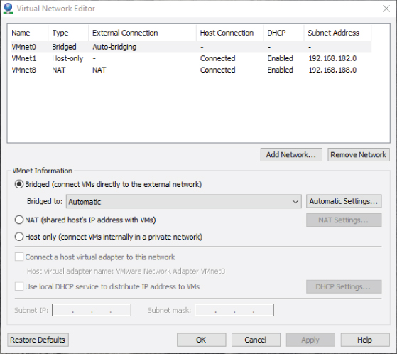
Figure 10.10 The Virtual Network Editor
A bridged network allows each virtual machine to have an IP address that is recognized and reachable from outside the host. The virtual adapter, in this case VMnet0, behaves as a virtual switch and merely routes the outbound traffic to its associated physical NIC and out to the physical network. When inbound traffic appears through the NIC, VMnet0 again acts as a switch and directs the traffic to the correct virtual machine. Figure 10.11 shows a simple illustration of two virtual machines connected to a bridged network configuration. Their IP addresses allow them to be seen by other systems on the local network. Again, because VMware Workstation Player is a Type 2 hypervisor, the virtual adapter construct acts as the virtual switch the Type 1 hypervisors utilize.

Figure 10.11 A simple bridged network
By highlighting VMnet0 in the Virtual Network Editor, you can see the bridged configuration. By default, the external connection is set to Auto-Bridging, meaning it will bind to an adapter that has a physical network connection. If you want to select the physical network connections used for the bridged connection, you can select the pull-down menu next to Bridged to label and change the current Automatic setting to a specific network adapter. You can also modify the Auto-Bridging list, choose Automatic Settings, and, as shown in Figure 10.12, select or deselect the appropriate adapters.
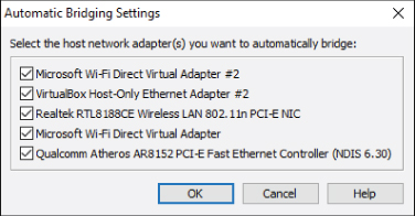
Figure 10.12 Automatic bridging settings
A host-only network will create the equivalent of an internal-only network, allowing virtual machines to communicate with other virtual machines on that network, but without an external connection to the physical network. Systems on the physical network would have no awareness of these virtual machines, nor any way to communicate with them. In your installation of VMware Workstation Player, a virtual machine connected to a host-only network would have access to services on the local machine and the local machine could access the services on the virtual machine. By highlighting VMnet1 in the Virtual Network Editor, you can see the configuration settings for the host-only network. As shown in Figure 10.13, there are a number of configuration settings you can adjust. The Subnet IP field allows you to determine the address you will assign to the isolated host-only network. By selecting the Use Local DHCP checkbox, you have the ability to have the local host automatically allocate and assign addresses to the virtual machines connected to this network. If you want to examine or adjust the default DHCP settings, click the DHCP Settings button, and the current parameters for address and lease times will be displayed and available to alter.
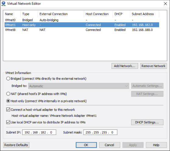
Figure 10.13 Host-only network settings
NAT stands for Network Address Translation. A NAT network is, in a way, a blending between the host-only and the bridged networks. Virtual machines connected to the NAT network have IP addresses that are isolated from the physical network, but they have access to the network outside of their host. Figure 10.14 shows a simple example of a virtual machine with a NAT connection. Each virtual machine has an IP address that is recognized by other virtual machines on the internal network, but that address is not visible from outside of the host. Each virtual machine, also shares the physical host's IP address for the external network. When the virtual machine sends a network request outside of the host, the hypervisor maintains a table of address translations from the internal to the external networks. When network data arrives, the physical NIC passes it to the hypervisor to retranslate the address and route the information to the correct virtual machine.

Figure 10.14 A simple NAT configuration
In the Virtual Network Editor, by highlighting VMnet8, you can see the NAT configuration as illustrated in Figure 10.15. Like the host-only network, you can create the private subnet. Also like the host-only network, you can have the DHCP service automatically provide IP addresses for the virtual machines connected to the NAT network. In VMware Workstation Player, NAT is the default setting when you create a virtual machine. For one thing, it will protect the newly created operating system from the outside world until you have time to install and configure security and antivirus software. NAT networks can also protect your network topology. With one IP address presented to the external network, the number and function of any virtual machines are hidden from unwanted investigation.
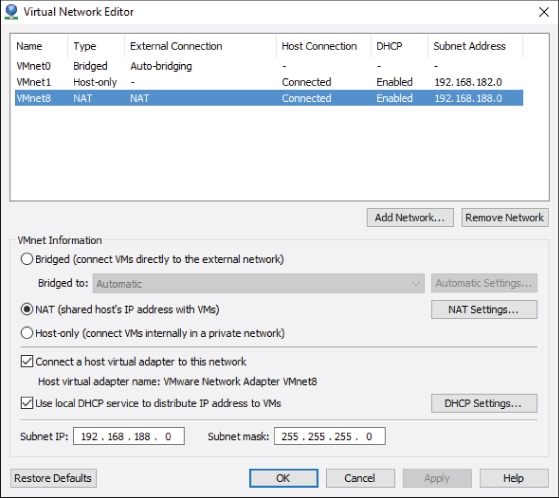
Figure 10.15 NAT network configuration settings
Tuning Practices for Virtual Networks
As you saw with storage virtualization, good practices in a physical network architecture work just as well in a virtual network environment. Physical networks use switches to isolate traffic for performance and security considerations. Those same practices carry through into virtual networks. Virtual switches tied to physical NICs can continue the physical segmentation into the virtual networking. A virtual network can be made just as complex and sophisticated as a physical network. One advantage that virtual networking maintains over physical networking from a cost and maintenance standpoint is the lack of cabling, or at least a tremendous reduction.
As you saw with memory and CPU virtualization, network virtualization is also very sensitive to performance impacts due to throughput pressure. As you consolidate ten individual servers onto a single virtualization host, you must plan for that host to carry the aggregated throughput. In the early days of virtualization, hosts might have eight, or ten, or more NICs in order to support the necessary bandwidth to provide adequate throughput and performance. This provided additional network processing capability by adding more processors with each NIC, and it provided physically separate pathways for the data to travel through, rather than relying on software to keep the data flow separate. Experience also recommended not mixing certain traffic types together at the expense of performance. Today, though, we are in a transitional period in which more data is traveling through fewer devices.
In the first Ghostbusters movie, Harold Ramis's character, Egon Spengler, tells his fellows, “Don't cross the streams,” when he is prepping them on using their proton packs. When asked why, he responds, “It would be bad.” This is how mixing traffic types on a single NIC was treated until recently. Now there are new NICs, converged network adapters, or CNAs, which handle greater bandwidth and sometimes multiple protocols. This helps reduce the number of network cards in the servers, but the issue of bandwidth contention still remains. As you saw in managing storage I/O, there are software features in the hypervisor to do the same in network I/O control. VMware's hypervisor has the ability to flag various network traffic types—data, storage, etc.—and assign bandwidth priorities to each type when network contention occurs. This control can be as granular as an individual virtual machine, a group of virtual machines that comprise an important application, or traffic from a particular set of addresses. At the moment, VMware's ESXi is the only hypervisor with this solution. Similar capabilities exist in some form in certain vendors' CNAs. With these technologies, you can have multiple network traffic types share the same bandwidth. Of course, at the end of Ghostbusters, they do mix the streams and everything works out just fine. It does here as well.
One of the downsides of consolidation is that multiple virtual machines are on a single host. They communicate across a virtual network in that host through virtual switches that are also inside the host. When a virtual machine sends information to another virtual machine on the same host, the external network never sees the transaction. This is good for performance, but bad for overall network management and debugging. If an application user complains of poor performance, the traditional network tools cannot see inside of the host. In the past, networking teams often surrendered the network configuration and management of the virtual network to the virtualization teams. The network teams had no experience or knowledge of the virtual environment's management tools, while the virtualization team was leery of having the network team work inside the virtualization host. As solutions have evolved, there are now tools that allow a network team to see inside a host and monitor the virtual network. Cisco has developed virtual switches that plug into a hypervisor and replace the vendor's virtual switch. The Cisco virtual switch is built on a Cisco switch operating system and uses all of the interfaces and tools of the physical Cisco switches. This means the network team does not need to learn new technology and the virtualization team can return the network responsibilities without concern.
Another challenge facing a virtualization administrator is that the standard virtual switches managed by the hypervisor are tied to the hosts on which they reside. When a switch needs to be configured, the administrator connects to the host and does that configuration. When a new host is added to the virtual cluster, the virtual switches need to be configured as part of setting up the host. When wider changes need to be applied to the network infrastructure, each of the virtual switches needs to be individually managed. This might not be an issue in a smaller environment, but in one that contains hundreds or even thousands of hosts, the work can become onerous, mind-numbing, and prone to error. Of course, these types of changes can be automated via scripting or other tools, but those items also need to be managed and maintained. Fortunately, as solutions in the virtual environment have matured, a solution has developed to help with these problems.
Each switch, physical and virtual, has two categories of work that it performs. The first group handles the data as it flows through the switch in whatever manner it was configured to do. Another name for this class of functions is the data plane. The second group handles all of the management capabilities that define what the data plane can and should do. A virtual distributed switch splits the work that switches perform into two parts. The data plane functionality remains with the virtual switches on the individual hosts, which makes logical sense. The management capabilities, however, are abstracted from the individual hosts and aggregated into a single management point. Instead of needing to adjust many virtual switches when a change needs to occur, an administrator now has a single place to make that change, and the same change is propagated out to all appropriate switches on the virtualization hosts. VMware's Distributed Switch, Hyper-V Virtual Switch, Cisco's Nexus 1000V (for VMware, KVM, and Hyper-V), and Open vSwitch (see openvswitch.org) are all examples of this. This is an oversimplification of a sophisticated and complex topic, but this is another example that the technologies are still evolving.
Finally, concluding this discussion of networking and evolution is the emergence of software-defined networks. Just as computing and its resources have been abstracted from server hardware through the development of hypervisors, a similar transformation is underway in the network area. Solutions have been developed that move network configuration and management away from specialized hardware where it has traditionally been. Not just switching and routing of data, but other functions such as firewalls, load balancing, and virtual private network (VPN) can now be deployed as virtual appliances—prebuilt virtual machines that are already loaded with everything they need to run their specific application or service. Virtual appliances are covered in more detail in Chapter 14, “Understanding Applications in a Virtual Machine.” Just as most server deployment and operation now takes place in virtual environments, the same is likely to be true for networking in the near future. This is a crucial building block in creating software-defined data centers, entities that are wholly defined in software and are deployed rapidly and repeatedly on many types of nondifferentiated hardware stacks of compute, storage, and network resources. Today, virtual machines can be migrated from one environment to another or from a data center to the cloud. As network virtualization matures, entire virtual data centers will follow.