
4
802.11n Interface
4.1. MAC layer evolution
Table 4.1 summarizes the features provided by the MAC (Medium Access Control) layer.
Table 4.1. Features of MAC layer
| Features | Mandatory/optional | Description |
| Reception A-MPDU | Mandatory | MAC frame aggregation |
| Transmission A-MPDU | Optional | |
| Reception A-MSDU | Mandatory | Aggregation of MAC frame payload |
| Transmission A-MSDU | Optional | |
| Block Ack | Mandatory | Acknowledgment for a block of MAC frames |
| Protection | Mandatory | Detection of radio channel occupancy time by non-802.11n compatible stations |
| RIFS | Mandatory | Reduced inter-frame interval |
| Spatial Multiplexing Power Save | Mandatory | Power save by reducing the number of spatial flows |
| Power Save Multi-Poll | Optional | Power save by modifying the radio access procedure for smaller frames |
| Non–TKIP | Mandatory | TKIP is no longer allowed |
| Phased Coexistence Operation | Optional | Alternating radio channels at 20 and 40 MHz |
4.1.1. Management frames
4.1.1.1. HT Capabilities information element
The management frames indicate that the access point has an 802.11n interface by including the HT (High Throughput) Capabilities information element.
The information provided by the HT Capabilities Info field is described in Table 4.2.
Table 4.2. Information of HT Capabilities Info field
| Information | Designation |
| LDPC Coding Capability | LDPC error correction code |
| Supported Channel Width Set | Bandwidth of the radio channel (20 MHz / 40 MHz) |
| SM Power Save | Power save for spatial multiplexing |
| HT_Greenfield | HT_GF format for PLCP header |
| Short GI for 20 MHz | Short guard interval for the 20 MHz radio channel |
| Short GI for 40 MHz | Short guard interval for the 40 MHz radio channel |
| Tx STBC | Transmission for the space-time diversity STBC |
| Rx STBC | Reception for the space-time diversity STBC |
| HT-Delayed Block Ack | Delayed acknowledgment mechanism |
| Maximum A-MSDU Length | Maximum size of frame aggregation A-MPDU (3,839 or 7,935 bytes) |
| DSSS/CCK Mode in 40 MHz | Using the DSSS/CCK mode for 40 MHz radio channel |
| Forty MHz Intolerant | Prohibition to use 40 MHz radio channel |
| L-SIG TXOP Protection Support | L-SIG TXOP protection mechanism |
A-MPDU Parameters: this field indicates the maximum size of the frame aggregation A-MPDU that the access point can receive and the minimum time between two MPDU data units of the aggregation.
Supported MCS Set: this field indicates the modulation and coding schemes supported by the access point, for transmission and reception.
HT Extended Capabilities: this field indicates whether PCO (Phased Coexistence Operation) mode or RD (Reverse Direction) protocol is supported.
Transmit Beamforming Capabilities: this field describes the supported features for beamforming.
ASEL Capability: this field describes the supported features for antenna selection.
The HT Capabilities information element is included in BEACON frames so that mobiles can determine that the 802.11n interface is available.
A mobile inserts the HT Capabilities information element into the PROBE REQUEST frame to search for 802.11n access points.
The HT Capabilities information element is also included in the management frames ASSOCIATION REQUEST, ASSOCIATION RESPONSE, REASSOCIATION REQUEST, REASSOCIATION RESPONSE and PROBE RESPONSE.
4.1.1.2. HT Operation information element
The HT Operation information element provides the mobile with the characteristics of the 802.11n interface and contains the following fields:
Primary Channel: this field indicates the number of the primary radio channel. This channel is used for management frames.
Secondary Channel Offset: this field indicates whether the secondary radio channel has a frequency higher or lower than that of the primary channel.
STA Channel Width: this field indicates the bandwidth that the access point uses in reception.
RIFS mode: this field indicates whether the use of the reduced interframe space (RIFS) is allowed.
HT Protection: this field indicates the protection mechanism to avoid interference with mobiles that are not compatible with the 802.11n interface.
Non-greenfield STA present: this field indicates if the HT_GF mode is supported by the access point.
OBSS Non-HT STAs present: this field indicates that an overlapping basic service set (OBSS) contains mobiles that are not compatible with the 802.11n interface requiring protection.
Dual Beacon, Dual CTS, STBC Beacon: these three modes are used when the beacon channel uses the diversity in STBC transmission.
L-SIG Protection Full Support: this field indicates whether the L-SIG protection mechanism is supported.
PCO Active, PCO Phase: these two fields indicate the use of the PCO mode, which makes it possible to switch a radio channel between 20 and 40 MHz. These fields are used to indicate that the PCO mode is in operation and whether the radio channel is currently 20 or 40 MHz.
Basic MCS set: this field indicates the modulation and coding schemes supported by the access point.
The HT Operation information element is included in the management frames BEACON, ASSOCIATION RESPONSE, REASSOCIATION RESPONSE and PROBE RESPONSE.
4.1.2. Structure of the MAC header
The 802.11n interface modifies the structure of the protocol header by adding the HT Control field (Figure 4.1) after the QoS Control field.
The presence of the HT Control field is indicated by the Order bit of the Frame Control field set to ONE, for QoS Data traffic frames and management frames.
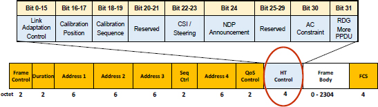
Figure 4.1. Structure of MAC header
The information provided by the Link Adaptation Control field is described in Table 4.3.
Table 4.3. Information of Link Adaptation Control field
| Information | Designation |
| TRQ (Training Request) | Request for the transmission of a PPDU sounding |
| MAI (MCS request and ASEL Indication) | Interpretation of MFB/ASELC information |
| MFSI (MCS Feedback Sequence Identifier) | Identifier of the sequence relating to a request for a recommendation on the value of the modulation and coding scheme (MCS) |
| MFB/ASELC (MCS Feedback and Antenna Selection Command) | MCS recommended value or features of antenna selection |
Calibration Position: this field indicates the position in the exchange sequence relative to the calibration sounding.
Calibration Sequence: this field contains the identifier of the exchange sequence.
CSI/Steering: this field indicates the type of response for beamforming.
NDP Announcement: this field indicates whether an empty frame is transmitted after the data unit.
AC Constraint: this field indicates whether the data in the RD protocol belongs to a single access category (AC).
RDG More PPDU: this field is interpreted differently, for the RD protocol, if it is transmitted by the initiator (allocation of a resource or not) or the responder (the frame is the last transmitted or not).
4.1.3. Frame aggregation
4.1.3.1. A-MPDU frame
The A-MPDU (Aggregate MAC Protocol Data Unit) frame is an A-MPDU sub-frame sequence (Figure 4.2). Each A-MPDU sub-frame contains a delimiter, an MPDU frame and pad bytes.

Figure 4.2. Structure of A-MPDU frame
With the exception of the last A-MPDU sub-frame, the padding bytes are added so that the size of each A-MPDU sub-frame is a multiple of four bytes.
The delimiter contains the size of the MPDU frame, an error check (CRC) on the frame size and a signature that can be used to detect a delimiter. The unique pattern is set to 4E in hexadecimal notation.
As each A-MPDU sub-frame gets its own MAC header, the encryption is applied to each sub-frame independently. Since each A-MPDU sub-frame has its own error detection sequence, an error will only affect the A-MPDU sub-frame, and the other A-MPDU sub-frames can be recovered.
All A-MPDU sub-frames must have the same destination on the radio link. On the other hand, the destination or the source address of the MPDU frame may be different.
4.1.3.2. A-MSDU frame
The A-MSDU (Aggregate MAC Service Data Unit) frame is a sequence of A-MSDU sub-frames (Figure 4.3). Each A-MSDU sub-frame contains an A-MSDU header, an MSDU data unit and pad bytes.

Figure 4.3. Structure of A-MSDU frame
The A-MSDU header consists of three fields: the MAC addresses of the destination and source of the MAC frame and the length of the MSDU data unit.
With the exception of the last A-MSDU sub-frame, padding bytes are added so that the size of each A-MSDU sub-frame is a multiple of four bytes.
Since the A-MSDU sub-frames of the same A-MSDU frame are contained in the same MPDU data unit, the same encryption applies to all the sub-frames.
Both forms of aggregation may be combined: an A-MPDU frame may contain an A-MSDU frame.
4.1.4. Control frames
4.1.4.1. Block acknowledgment
The block acknowledgment mechanism improves the efficiency of the channel by grouping multiple acknowledgments in a single control frame. There are two types of mechanisms: immediate acknowledgment and delayed acknowledgment.
The immediate acknowledgment mechanism is suitable for high-bandwidth and low-latency applications, whereas the delayed acknowledgment mechanism is suitable for applications that tolerate moderate latency.
The original design of the acknowledgment mechanism requires that each transmitted frame be acknowledged separately by the Ack control frame (Figure 4.4).

Figure 4.4. Block acknowledgment
If the immediate acknowledgment mechanism is used, then the recipient must respond to a BlockAckReq frame with a BlockAck frame (Figure 4.4). When the recipient sends the BlockAck frame, the initiator retransmits all frames that are not acknowledged in the BlockAck frame, either in another block or individually.
If the delayed acknowledgment mechanism is used, then the recipient must respond to a BlockAckReq control frame with an Ack control frame. The recipient must then send his response in a BlockAck control frame, which the initiator acknowledges by an Ack control frame (Figure 4.4).
The block acknowledgment mechanism has been introduced with the QoS mechanism. The block acknowledgment mechanism was initially optional, but the efficiency gains coupled with the aggregate frame transmission resulted in BlockAck control frame support being required for the 802.11n interface.
The initial definition of the block acknowledgment mechanism took into account the processing of frame-related sequence numbers and fragment numbers. For the 802.11n interface, the block acknowledgment mechanism can be compressed, thus only processing the sequence number.
4.1.4.2. Control frame structure
The BlockAckReq control frame is transmitted by the source of several MAC frames for block acknowledgment (Figure 4.5).

Figure 4.5. Control frame structure
The BAR or BA Control field contains the following information:
- – Ack Policy: this bit indicates whether the block acknowledgment is immediate (bit to ZERO) or not (bit to ONE);
- – Multi-TID: this bit indicates whether the block acknowledgment applies to several priority levels (bit to ONE) or not (bit to ZERO);
- – Compressed Bitmap: this bit indicates whether the block acknowledgment is compressed (bit to ONE) or not (bit to ZERO);
- – TID_INFO: this four-bit coded subfield provides the value of the TID (Traffic Identifier) field, for which a block acknowledgment is required.
The BAR or BA Information field contains the value of the sequence number of the first transmitted MAC frame. If the block acknowledgment applies to several priority levels, the sequence number is indicated for each priority level.
The BlockAck control frame is transmitted by the recipient of the MAC frames for block acknowledgment. Each bit in the bitmap of the Information field acknowledges (bit to ONE) or not (bit to ZERO) the frame that has this offset from the initial sequence number.
4.2. PLCP sub-layer
The PLCP (Physical Layer Convergence Procedure) sub-layer supports the following three modes:
- – NON_HT mode: the PLCP header is identical to that defined for the 802.11a/g interfaces (Figure 4.6). NON_HT mode support is required;
- – HT_MF (Mixed Format) mode: the PLCP header contains a preamble compatible with that defined for the 802.11a/g interfaces so that it can be processed by mobiles that do not handle the 802.11n interface (Figure 4.6). HT_MF mode support is required;
- – HT_GF (Greenfield) mode: the PLCP header does not contain fields compatible with the 802.11a/g interfaces (Figure 4.6). Support for HT_GF format is optional. A mobile that does not support the HT_GF mode must be able to detect that a transmission of an HT_GF frame is in progress.

Figure 4.6. PLCP frame structure
L-STF (Non-HT Short Training Field): this field is identical to the short training sequence of the 802.11a/g interfaces.
L-LTF (Non-HT Long Training Field): this field is identical to the long training sequence of the 802.11a / g interfaces.
L-SIG (Non-HT Signal): this field is identical to the SIGNAL field of the 802.11a/g interfaces. This field allows mobiles that do not handle the 802.11n interface to determine the radio channel occupancy time, the bit rate being 6 Mbps.
HT-SIG (HT Signal): Table 4.4 describes the information in this field.
Table 4.4. HT-SIG field structure
| Information | Bit number | Designation |
| MCS | 7 | Index of the modulation and coding scheme (76 values) |
| Channel Bandwidth | 1 | Bit to ZERO for a bandwidth at 20 MHz Bit at ONE for a bandwidth at 40 MHz |
| HT Length | 16 | Size in bytes of the PSDU payload |
| Smoothing | 1 | Bit to ONE for smoothing the assessment of channel aggregation. Bit to ZERO for independent assessment of each channel |
| Not Sounding | 1 | Bit to ZERO if the PPDU data unit is a sounding Bit to ONE if not |
| Aggregation | 1 | Bit to ONE if the data unit contains A-MPDU sub-frames ZERO bit if not |
| STBC (Space-Time Block Coding) | 2 | 2 bits to ZERO if transmission diversity is not used If not, value indicating the difference between the number of spatial/temporal diversity streams and the number of spatial flows |
| FEC (Forward Error Correction) | 1 | Bit to ZERO for LDPC (Low-Density Parity Check) coding Bit to UN for BCC (Binary Convolutional Code) coding |
| Short GI (Guard Interval) | 1 | Bit to ONE if a short guard interval is used ZERO bit if not |
| Number of extension spatial streams | 2 | Indicates the number of extension spatial streams. Set to 0 for no extension spatial stream. Set to 1 for 1 extension spatial stream. Set to 2 for 2 extension spatial streams. Set to 3 for 3 extension spatial streams. |
| CRC | 8 | Cyclic redundancy code |
| Tail | 6 | Tail of the convolutional encoder |
HT-STF (HT Short Training Field): this field has the same purpose as the L-STF field.
There are two types of HT-LTF (HT Long Training Field):
- – DATA HT-LTF field helps to set the MIMO (Multiple Input Multiple Output) mechanism;
- – HT-LTF Extension field is used for beamforming. The number of HTF LTF fields depends on the number of spatial flows. This field is optional.
4.3. PMD sub-layer
Table 4.5 summarizes the features provided by the PMD (Physical Medium Dependent) sub-layer.
Table 4.5. Characteristics of PMD sub-layer
| Features | Mandatory/optional |
| BPSK, QPSK, 16QAM, 64QAM Modulation | Mandatory |
| BCC error correction code | Mandatory |
| LDPC error correction code | Optional |
| Short guard interval (400 ns) | Optional |
| MIMO (up to four streams) | Optional |
| Beamforming | Optional |
| STBC | Optional |
4.3.1. Transmission chain
Transmission in the HT_MF and HT_GF modes is generated from the following function blocks:
- a) Scrambler scrambles the data to reduce the probability of long sequences of bits to ZERO or to ONE.
- b) Encoder parser, if BCC encoding is to be used, demultiplexes the scrambled bits among NES (number of BCC encoders for the Data field) BCC encoders, in a round robin manner.
- c) FEC encoders encode the data to enable error correction. An FEC encoder may include a binary convolutional encoder followed by a puncturing device, or it may include an LDPC encoder.
- d) Stream parser divides the outputs of the encoders into blocks that are sent to different interleaver and mapping devices. The sequence of the bits sent to an interleaver is called a spatial stream.
- e) Interleaver interleaves the bits of each spatial stream (changes order of bits) to prevent long sequences of adjacent noisy bits from entering the BCC decoder. Interleaving is applied only when BCC encoding is used.
- f) Constellation mapper maps the sequence of bits in each spatial stream to constellation points (complex numbers).
- g) STBC encoder spreads constellation points from NSS spatial streams into NSTS space-time streams using a space-time block code. STBC is used only when NSS<NSTS.
- h) Spatial mapper maps space-time streams to transmit chains. This may include one of the following:
- – direct mapping: constellation points from each space-time stream are mapped directly onto the transmit chains (one-to-one mapping);
- – spatial expansion: vectors of constellation points from all the spacetime streams are expanded via matrix multiplication to produce the input to all the transmit chains;
- – beamforming: similar to spatial expansion, each vector of constellation points from all the space-time streams is multiplied by a matrix of steering vectors to produce the input to the transmit chains.
- i) Inverse discrete Fourier transform (IDFT) converts a block of constellation points to a time domain block.
- j) CSD (Cyclic Shift Diversity) insertion is where the insertion of the cyclic shifts prevents unintentional beamforming. CSD insertion may occur before or after the IDFT.
- k) GI insertion prepends to the symbol a circular extension of itself.
- l) Windowing optionally smooths the edges of each symbol to increase spectral decay.
Figure 4.7 shows the blocks used to generate the HT-SIG field of the PPDU data unit in HT_MF mode.
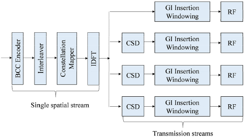
Figure 4.7. Transmission chain – Diagram 1
These blocks are also used to generate the NON_HT part of the PPDU data unit in HT_MF mode.
The BCC encoder and the interleaver are not used when generating the L-STF and L-LTF fields.
Figure 4.8 shows the blocks used to generate the DATA field for HT_MF and HT_GF modes.
A subset of these blocks consisting of the constellation mapper and the CSD blocks, as well as the blocks on the right, including the spatial mapping block, is also used to generate the HT-STF, HT-GF-STF and HT-LTF fields.
The HT-GF-SIG field is generated using the blocks shown in Figure 4.7, augmented by additional CSD blocks and spatial mapping.

Figure 4.8. Transmission chain – Diagram 2
4.3.2. Frequency plan
The 802.11n interface operates in the N-NII (Unlicensed-National Information Infrastructure) band, at 5 GHz, as the 802.11a interface, and in the ISM (Industrial, Scientific and Medical) band, at 2.4 GHz, as the 802.11g interface.
The 802.11n interface uses the 20 MHz radio channel, as for the 802.11a/g interfaces, and offers the possibility of aggregating two adjacent radio channels in the U-NII band at 5 GHz (Figure 4.9).

Figure 4.9. Frequency plan
4.3.3. Frequency multiplexing
For the 20 MHz radio channel band, for HT modes, the complex numbers are numbered 0 to 51 and are subsequently mapped onto OFDM (Orthogonal Frequency-Division Multiplexing) sub-carriers, numbered −28 to −22, −20 to −8, −6 to −1, 1 to 6, 8 to 20 and 22 to 28 (Table 4.6).
Sub-carriers −21, −7, 7 and 21 are ignored and subsequently used for the insertion of pilot sub-carriers.
Table 4.6. OFDM multiplexing parameters
| Parameters | NON_HT | HT 20 MHz | HT 40 MHz |
| NSD Number of sub-carriers assigned to the DATA field | 48 | 52 | 108 |
| NSP Number of sub-carriers assigned to pilots | 4 | 4 | 6 |
| NST Total number of sub-carriers | 52 | 56 | 114 |
| ΔF Spacing between sub-carriers | 0.3125 MHz (20 MHz/64) | ||
For the 40 MHz radio channel band, the complex numbers are numbered 0 to 107 and are subsequently mapped onto OFDM sub-carriers numbered −57 to −54, −52 to −26, −24 to −12, −10 to −1, 1 to 10, 12 to 24, 26 to 52 and 54 to 57 (Table 4.6).
Sub-carriers −53, −25, −11, 11, 25 and 53 are ignored and subsequently used for the insertion of pilot sub-carriers.
Sub-carrier 0, associated with the central frequency, is omitted and filled with the value of ZERO.
4.3.4. Space multiplexing
4.3.4.1. MIMO mechanism
The MIMO mechanism consists of simultaneously transmitting m signals and receiving them on n antennas, with m <n, using the same radio channel. Each receiving antenna receives the m transmitted signals, each signal being modified by the transfer function between the transmitting and receiving antennas. There is thus a transmission matrix H of size m × n (Figure. 4.10).
The MIMO mechanism, by spatially multiplexing m signals, makes it possible to increase the rate of the radio channel with the same factor.
The MIMO mechanism uses the transmission matrix H to perform spatial demultiplexing.
For the SU (Single User) MIMO mechanism, the m transmitted signals are destined for the same user.

Figure 4.10. MIMO mechanism
4.3.4.2. STBC mechanism
When the number of transmitters (m) is greater than the number of receivers (n), the additional transmitters are used to effect transmit diversity, thereby improving the quality of the received signal by protecting the transmission from fading.
The STBC mechanism performs space and time diversity. The signal S corresponding to a spatial flux is divided into two parts, S1 and S2. The complex numbers of the S (= S1 + S2) constellation of NSS spatial streams (NSS = 1) are distributed over NSTS space-time flows (NSTS = 2) (Figure 4.11).

Figure 4.11. STBC mechanism
4.3.4.3. Beamforming
Beamforming allows a transmitter, called a beamformer, to focus the energy of several sources of the same signal in the direction of the receiver, called a beamformee. Phase reception increases the signal-to-noise ratio of the received signal (Figure 4.12).

Figure 4.12. Beamforming mechanism
For the explicit beamforming, a device measures the radio channel and uses this measurement to directly calculate the direction matrix. The active channel measurement is performed by transmitting a sounding to the beamformee, which responds with a frame that indicates how the sounding was received.
For implicit beamforming, frames such as ACK control frames or data transmitted on pilot channels can be used to estimate the direction matrix.
4.3.5. Modulation and coding scheme
The value of the modulation and coding scheme (MCS) determines the rate value from the following parameters:
- – the modulation of the sub-carriers, phase modulation (BPSK or QPSK) or mixed phase and amplitude modulation (16-QAM or 64-QAM);
- – the coding rate of the error correction code, which can take values of 1/2, 2/3, 3/4 or 5/6;
- – the number of spatial flows of the MIMO mechanism, which can take values of 1, 2, 3 or 4;
- – the bandwidth of the radio channel, which may be 20 or 40 MHz;
- – the duration of the guard interval, short duration of 400 ns or long duration of 800 ns.
Table 4.7 (respectively Table 4.8) provides the rate values, for a single spatial stream, for the first eight MCS values (between 0 and 7), for a bandwidth of 20 MHz (respectively 40 MHz).
Table 4.7. Parameters of the modulation and coding scheme 20 MHz bandwidth
| Modulation | Coding rate | Number of bits per sub-carrier | Number of DATA bits per OFDM symbol | Number of encoded DATA bits | Rate (Mbps) | |
| GI 800 ns | GI 400 ns | |||||
| BPSK | 1/2 | 1 | 26 | 52 | 6.5 | 7.2 |
| QPSK | 1/2 | 2 | 52 | 104 | 13.0 | 14.4 |
| QPSK | 3/4 | 2 | 78 | 104 | 19.5 | 21.7 |
| 16-QAM | 1/2 | 4 | 104 | 208 | 26.0 | 28.9 |
| 16-QAM | 3/4 | 4 | 156 | 208 | 39.0 | 43.3 |
| 64-QAM | 2/3 | 6 | 208 | 312 | 52.0 | 57.8 |
| 64 QAM | 3/4 | 6 | 234 | 312 | 58.5 | 65.0 |
| 64-QAM | 5/6 | 6 | 260 | 312 | 65.0 | 72.2 |
Table 4.8. Parameters of the modulation and coding scheme 40 MHz bandwidth
| Modulation | Coding rate | Number of bits per sub-carrier | Number of DATA bits per OFDM symbol | Number of encoded DATA bits | Rate (Mbps) | |
| GI 800 ns | GI 400 ns | |||||
| BPSK | 1/2 | 1 | 54 | 108 | 13.5 | 15.0 |
| QPSK | 1/2 | 2 | 108 | 216 | 27.0 | 30.0 |
| QPSK | 3/4 | 2 | 162 | 216 | 40.5 | 45.0 |
| 16-QAM | 1/2 | 4 | 216 | 432 | 54.0 | 60.0 |
| 16-QAM | 3/4 | 4 | 324 | 432 | 81.0 | 90.0 |
| 64-QAM | 2/3 | 6 | 432 | 648 | 108.0 | 120.0 |
| 64 QAM | 3/4 | 6 | 486 | 648 | 121.5 | 135.0 |
| 64-QAM | 5/6 | 6 | 540 | 648 | 135.0 | 150.0 |
The MCS values between 8 and 15 are relative to two spatial streams, for a bandwidth of 20 or 40 MHz.
The MCS values between 16 and 23 are relative to three spatial streams, for a bandwidth of 20 or 40 MHz.
The MCS values between 24 and 31 are relative to four spatial streams, for a bandwidth of 20 or 40 MHz.
The MCS values between 33 and 76 correspond to the STBC mechanism for which:
- – two spatial flows (NSS=2) are coded in three space-time flows (NSTS = 3);
- – three spatial flows (NSS=3) are coded in four space-time flows (NSTS = 4).
MCS values between 0 and 15, with a guard interval of 800 ns and a bandwidth of 20 MHz are required. Other MCS values, 400 ns guard interval and 40 MHz bandwidth are optional.
The MCS value of 32 has the characteristics described in Table 4.9.
Table 4.9. MCS 32 parameters
| Modulation | Coding rate | Number of bits per sub-carrier | Number of DATA bits per OFDM symbol | Number of encoded DATA bits | Rate (Mbps) | |
| GI 800 ns | GI 400 ns | |||||
| BPSK | 1/2 | 1 | 24 | 48 | 6.0 | 6.7 |