9
S2c Tunnel Establishment
9.1. MIPv6 mechanism
The MIPv6 (Mobile Internet Protocol version 6) mechanism allows a moving host to keep its original IPv6 address, in order to maintain its current session or to be reachable on the move, mobility being managed by the host.
The mobile node (MN) is a host that changes network while retaining the home address (HoA) of its home network. When attached to a foreign network, it acquires an additional care-of address (CoA) (Figure 9.1).

Figure 9.1. Components for MIPv6 mechanism
The home agent (HA) is the entity of the originating network from which the mobile node must register when it attaches to a foreign network. The role of the host agent is to intercept the received packets and send them back in a tunnel to the mobile node. The home agent address (HAA) is that of the interface of the home agent on the home network of the mobile node (Figure 9.1).
The correspondent node (CN) is the host that exchanges packets with the mobile node. Its address is noted CNA (Correspondent Node Address) (Figure 9.1).
IPv6 mobility implements packet routing optimization between the mobile node and the correspondent node. The systematic routing of the packets exchanged via the home agent is simple to implement. On the other hand, if the mobile node is moving away from its home network and communicating with a correspondent node close to it, then it is more efficient to communicate directly rather than through the home agent.
9.1.1. IPv6 header extensions
9.1.1.1. Mobility extension
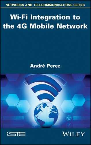
The mobility extension, described in Figure 9.2, is attached to the IPv6 header and allows the exchange of information between the mobile node, on the one hand, and the correspondent node or the home agent, on the other.
Figure 9.2. Mobility extension format
This information relates to the registration of the mobile node with the correspondent node or the host agent, for the association of addresses HoA and CoA.
The Next Header field in the header preceding the mobility extension has a value of 135.
Proto Payload: this field, coded on one byte, has a value of 59, indicating termination of extensions chaining.
Header Length: this field, coded on one byte, defines the size of the extension.
MH (Mobility Header) Type: this field, coded on one byte, defines the type of mobility extension:
- – 0) Binding Refresh Request. This extension is transmitted by the correspondent node or by the home agent to the mobile node in order to update the link between the HoA and CoA.
- – 1) Home Test Init (HoTI). This extension initializes the Return Routability procedure on the indirect path between the mobile node and the correspondent node.
- – 2) Care-of Test Init (CoTI). This extension initializes the Return Routability procedure on the direct path between the mobile node and the correspondent node.
- – 3) Home Test (HoT). This extension is the answer to the HoTI extension. It contains the cryptographic information (Home Keygen Token).
- – 4) Care-of Test (CoT). This extension is the answer to the HoTI extension. It contains the cryptographic information (Care-of Keygen Token).
- – 5) Binding Update. This extension is transmitted by the mobile node to link the HoA contained in the Home Address option of the Destination extension to the CoA contained in the source address of the IPv6 header or in the Alternate Care-of Address option.
- – 6) Binding Acknowledgment. This extension is passed by the correspondent node or by the home agent to acknowledge receipt of the Binding Update message.
- – 7) Binding Error. This message is transmitted by the correspondent node or by the home agent if the Binding Update message is incorrect.
Checksum: this field, coded on two bytes, contains the checksum calculated on the pseudo-header and the mobility extension.
Message Data: this variable size field contains the data corresponding to the type of mobility extension.
The mobility extension can also include the following options:
- – Pad1: this option is used to insert a padding byte;
- – PadN: this option is used to insert several bytes of padding;
- – Binding Refresh Advice: this option is associated with the mobility extension Binding Acknowledgment passed by the home agent. It specifies the value of the timer used by the mobile node to update its registration;
- – Alternate Care-of Address: this option is associated with the mobility extension Binding Update. It specifies the CoA if it cannot be deduced from the source address of the IPv6 header;
- – Nonce Indices: this option is associated with the mobility extension Binding Update passed to the correspondent node. It contains random numbers (nonce) needed for calculating cryptographic information (Home Keygen Token, Care-of Keygen Token);
- – Binding Authorization Data: this option is associated with the mobility extensions Binding Update and Binding Acknowledgment. It contains cryptographic information from which the destination can verify that the message originates from a node with which the Return Routability procedure has occurred.
9.1.1.2. Destination extension
The Home Address option of the Destination extension indicates the HoA of the mobile node.
The Destination extension is used for the direct transfer of data from the mobile node to the correspondent node.
The mobile node cannot use the HoA as the source address because the router of the foreign network can delete the packet if the source does not belong to the local network.
The mobile node is therefore obliged to retain the CoA as the source address.
In reception, the correspondent node must replace the CoA with the address HoA to reconstitute the socket.
9.1.1.3. Routing extension
The Routing extension (type 2) contains the HoA of the mobile node.
The Routing extension is used for the direct transfer of data from the correspondent node to the mobile node.
The correspondent node transmits the packet to the CoA destination address of the mobile node.
Upon receiving the packet, the mobile node replaces the CoA with the HoA of the Routing (type 2) extension to reconstruct the socket.
9.1.2. ICMPv6 messages
9.1.2.1. Message Home Agent Address Discovery Request
The message Home Agent Address Discovery Request is transmitted by the mobile node to the home agent. The source address is the CoA of the mobile node. The destination address is the anycast address constructed from the HoA of the mobile node. The value of the Type field of the ICMPv6 message is 144.
9.1.2.2. Message Home Agent Address Discovery Reply
The message Home Agent Address Discovery Reply is transmitted by the home agent in response to the previous message. It contains a list of HAA. The value of the Type field of the ICMPv6 message is 145.
9.1.2.3. Message Mobile Prefix Solicitation
The message Mobile Prefix Solicitation is transmitted by the mobile node to the host agent in order to update the configuration of its HoA. The source address is the CoA of the mobile node. The destination address is the HAA. The Destination extension must be inserted. The value of the Type field of the ICMPv6 message is 146.
9.1.2.4. Message Mobile Prefix Advertisement
The message Mobile Prefix Advertisement is transmitted by the home agent either in response to the previous message or in an unsolicited manner. In both cases, the destination address is the CoA of the mobile node. The Routing extension (Type 2) must be inserted. The value of the ICMPv6 message type field is 147. The ICMPv6 message incorporates the Prefix Information option.
9.1.2.5. ND protocol modifications
The changes to the ICMPv6 ND (Neighbor Discovery) protocol are as follows:
- – the RA (Router Advertisement) message is modified;
- – the Prefix Information option is modified;
- – the Advertisement Interval option is created;
- – the Home Agent Information option is created.
The H (Home Agent) flag is introduced in the Router Advertisement message to allow a home agent to discover other home agents on the home network.
The RA message uses the LINK-LOCAL address as the source address. The Prefix Information option includes the prefix used to set up the GLOBAL UNICAST address.
The home agent listening for Router Advertisement messages from other home agents cannot get their GLOBAL UNICAST address. The Prefix Information option introduces an R (Router Address) flag to signify that the announced prefix is actually a GLOBAL UNICAST address.
The Advertisement Interval option is passed in the Router Advertisement message to set the frequency of sending messages.
The Home Agent Information option is associated with the Router Advertisement message sent by the home agent. It specifies the level of preference of the home agent and its lifetime. The preference level is used by the home agent to order the home agent list transmitted in the message Home Agent Address Discovery Reply.
9.1.3. Procedures
9.1.3.1. Attachment of the mobile node to the home agent
When the mobile node detects a network change, it performs the DAD (Duplicate Address Detection) procedure with its LINK-LOCAL address.
It then discovers the network prefix by ICMPv6 messages, Router Solicitation and Router Advertisement; builds its CoA and verifies its uniqueness (Figure 9.3).

Figure 9.3. Attachment of the mobile node to the home agent
Sometimes, when the mobile node has to send a Binding Update message to its home agent to register its CoA, it may not know the HAA.
In this case, the mobile node may attempt to discover the address of a home agent by sending the message Home Agent Address Discovery Request using the anycast address corresponding to the prefix of its HoA.
The host agent that receives this request message returns the message Home Agent Address Discovery Reply containing the list of HAA (Figure 9.3).
The mobile node, after receiving the message Home Agent Address Discovery Reply, can then send the Binding Update message to one of the HAA.
The mobile node may attempt to register at each of these addresses, in the order they appear in the message Home Agent Address Discovery Reply, until its registration is acknowledged by receiving the Binding Acknowledgment message (Figure 9.3).
The home agent broadcasts the Neighbor Advertisement message to refresh the neighbor table of the hosts of the originating network, for which the HoA of the mobile node is associated with the Ethernet address of the home agent (Figure 9.3).
9.1.3.2. Data transfer
The transfer of packets between the correspondent node and the mobile node takes place initially through the home agent (Figure 9.4).
Packets from the correspondent node to the mobile node are intercepted by the home agent.
- Packet source address: CNA
- Packet destination address: HoA
The home agent encapsulates the packets received by a new IPv6 header to transfer them to the mobile node.
- Tunnel source address: HAA
- Tunnel destination address: CoA
- Packet source address: CNA
- Packet destination address: HoA
Packets from the mobile node to the correspondent node are forwarded in a tunnel to the home agent.
- Packet source address: HoA
- Packet destination address: CNA
- Tunnel source address: CoA
- Tunnel destination address: HAA
The home agent deletes the tunnel and forwards the packets to the correspondent node.
- Packet source address: HoA
- Packet destination address: CNA
The mobile node then implements the direct transfer procedure, initially initializing the Return Routability procedure. It then transmits the Binding Update message to the correspondent node to create the link between the CoA and HoA (Figure 9.4).

Figure 9.4. Data transfer
The transfer of packets between the correspondent node and the mobile node can then be carried out directly (Figure 9.4).
Packets from the correspondent node to the mobile node carry the following addresses:
- Packet source address: CNA
- Packet destination address: CoA
- Routing (type 2) extension: HoA
Packets from the mobile node to the correspondent node carry the following addresses:
- Packet source packet: CoA
- Packet destination address: CNA
- Destination extension: HoA
9.1.3.3. Local network change
When the mobile node communicating with the correspondent node changes a foreign network, it repeats the procedure in order to build its new CoA, through the messages Router Solicitation and Router Advertisement (Figure 9.5).

Figure 9.5. Network change of the mobile node
The mobile node resumes the operation of registering its CoA with its home agent by the messages Binding Update and Binding Acknowledgment (Figure 9.5)
When the mobile node has registered with its home agent, it triggers a registration at the correspondent node to update the CoA by the messages Binding Update and Binding Acknowledgment. This registration is preceded by the Return Routability procedure (Figure 9.5).
9.1.3.4. Return of the mobile node to the host network
A mobile node detects that it has returned to its home network when it detects its prefix in a Router Advertisement message. To be able to send and receive packets using its HoA, the mobile node must send a Binding Update message to its home agent to warn it to stop intercepting packets (Figure 9.6).

Figure 9.6. Return of the mobile node to the host network
By processing the Binding Update message, the home agent will stop responding to Neighbor Solicitation messages regarding the HoA of the mobile node. Upon receiving the Binding Acknowledgment message, the mobile node broadcasts the Neighbor Advertisement message to update the neighbor table of the hosts of the home network (Figure 9.6).
The mobile node renews the operation of registering its CoA with the correspondent node by the exchange of messages Binding Update and Binding Acknowledgment. This registration is preceded by the Return Routability procedure, limited to the exchange of HoTI and HoT messages (Figure 9.6).
9.1.3.5. Return Routability procedure
The Return Routability procedure allows the correspondent node to ensure that the mobile node is in fact accessible to its CoA and HoA. This assurance allows the correspondent node to accept the Binding Update message sent by the mobile node for the purpose of establishing a direct transfer.
The HoTI and CoTI messages are transmitted simultaneously by the mobile node to the correspondent node (Figure 9.7):
- – HoTI message passes through the home agent;
- – CoTI message is sent directly to the correspondent node.

Figure 9.7. Return Routability procedure
The HoT and CoT messages are the responses of the correspondent node to the mobile node (Figure 9.7):
- – HoT message contains the cryptographic information Home Keygen Token computed from the HoA, from a random number (nonce) and from the secret key Kcn of the correspondent node:
- First 64 bits HMAC_SHA1 (Kcn, (HoA | nonce | 0x00))
- – CoT message contains the cryptographic information Care-of Keygen Token calculated from the address CoA, a random number (nonce) and the secret key Kcn of the correspondent node:
- First 64 bits HMAC_SHA1 (Kcn, (CoA | nonce | 0x01))
Following the procedure, the mobile node has the data it needs to build a Kbm secret key by hashing the received data:
- Kbm = SHA1 (Home Keygen Token | Care-of Keygen Token)
The Binding Update message transmitted by the mobile node directly to the correspondent node contains the following cryptographic information:
- First 96 bits HMAC_SHA1 (Kbm, (CoA | CNA | Binding Update))
When the correspondent node has validated the received Binding Update message, it responds with the Binding Acknowledgment message with the following cryptographic information:
- First 96 bits HMAC_SHA1 (Kbm, (CoA | CNA | Binding Acknowledgement))
The procedure is based on the assumption that no intruder can listen to both HoT and CoT messages, these messages using two different paths to join the mobile node. Interception remains possible if the malicious node is connected to the network of the correspondent node.
The procedure is based on the shared Kbm secret that needs to be refreshed. Refreshment is left to the initiative of the correspondent node. An association change request Binding Update is denied through the Binding Error message. The mobile node must then restart the Return Routability procedure.
9.2. DSMIPv6 mechanism
The MIPv6 mechanism was designed for a mobile connection to an IPv6 network. The DSMIPv6 (Dual-Stack Mobile IP version 6) mechanism also takes into account the connection of the mobile to a public or private IPv4 network. This arrangement makes it possible to avoid unrolling the two MIPv4 and MIPv6 mechanisms when the mobile has a dual IPv4 and IPv6 stack.
Several types of tunnel can be built between the mobile and the PGW entity that hosts the home agent functions:
- – an IPv6 packet can be encapsulated by an IPv6 header;
- – an IPv6 packet can be encapsulated by an IPv4 header. When the mobile is connected to an IPv4 private network, the tunnel must insert a UDP header between the IPv6 and IPv4 headers, for traversal of the NAT (Network Address Translation) device;
- – an IPv4 packet can be encapsulated by an IPv6 header;
- – an IPv4 packet can be encapsulated by an IPv4 header. When the mobile is connected to an IPv4 private network, the tunnel must insert a UDP header between the two IPv4 headers for traversal of the NAT device.
The direct transfer between the mobile node and the correspondent node is not allowed, the mobile traffic in any case to be controlled by the PGW entity.
9.3. Application to the 4G mobile network
9.3.1. Trusted Wi-Fi access
The establishment of the S2c tunnel constitutes one of the different phases of the mobile attachment described in Figure 9.8.

Figure 9.8. S2c tunnel establishment Trusted Wi-Fi access
Phase (A) corresponds to the mutual authentication procedure described in Chapter 6. At the end of phase (A), trusted Wi-Fi access has recovered the service profile of the mobile stored in the HSS entity.
Phase (B) corresponds to the configuration of the mobile via trusted Wi-Fi. At the end of phase (B), the mobile recovers its CoA. Trusted Wi-Fi access can also initiate a session with the PCRF to retrieve the profile of the mobile stored in the SPR database.
Phase (C) is the establishment of an IPSec association between the mobile and the PGW entity to protect the DSMIPv6 control messages. The principles for establishing a security association are described in Chapter 7. At the end of phase (C), the PGW entity assigned the mobile its HoA and retrieved the service profile of the mobile stored in the HSS entity.
During phase (D), the mobile communicates to the PGW entity the HoA and CoA in the Binding Update message of the Mobility extension of the IPv6 header. During phase (D), the PGW entity can also initiate a session with the PCRF entity to retrieve the profile of the mobile stored in the SPR entity. The PGW terminates phase (D) by issuing the Binding Acknowledgment message of the Mobility extension of the IPv6 header. At the end of phase (D), the IP tunnel S2c is established between the mobile and the PGW entity.
9.3.2. Untrusted Wi-Fi access
The establishment of the S2c tunnel constitutes one of the different phases of the mobile attachment described in Figure 9.9.
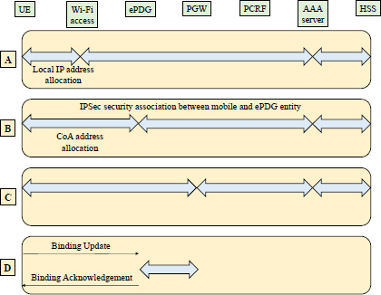
Figure 9.9. S2c tunnel establishment Untrusted Wi-Fi access
Phase (A) corresponds to the authentication procedure described in Chapter 6. At the end of phase (A), the untrusted Wi-Fi access has recovered the service profile of the mobile stored in the HSS entity. Untrusted Wi-Fi access provides the mobile with a Local IP Address to start Phase (B) of the procedure.
Phase (B) corresponds to the procedure for establishing the SWu tunnel described in Chapter 7. At the end of phase (B), an IPSec tunnel is established between the mobile and the ePDG entity, the ePDG entity has retrieved the service profile of the mobile stored in the HSS entity and assigned the mobile its CoA.
Phase (C) is the establishment of an IPSec association between the mobile and the PGW entity to protect the DSMIPv6 control messages. At the end of phase (C), the PGW entity allocated the mobile its HoA and retrieved the mobile service profile stored in the HSS entity.
During phase (D), the mobile communicates to the PGW entity the HoA and CoA in the Binding Update message of the Mobility extension of the IPv6 header. During phase (D), the PGW entity can also initiate a session with the PCRF entity to retrieve the profile of the mobile stored in the SPR entity. The PGW entity terminates phase (D) by issuing the Binding Acknowledgment message of the Mobility extension of the IPv6 header. At the end of phase (D), the IP tunnel S2c is established between the mobile and the PGW entity.
9.3.3. IFOM function
The IFOM (IP Flow Mobility) function allows the mobile to connect to both LTE (Long-Term Evolution) access and Wi-Fi access simultaneously and to establish multiple sessions from a single connection to the PGW entity.
The IFOM feature also allows mobility of the IP stream, with IP streams belonging to the same application or different applications moving seamlessly between LTE access and Wi-Fi access.
The IFOM function is used to indicate how the IP streams are routed through the different radio access networks and to selectively unload certain traffic (e.g. Internet traffic) to Wi-Fi access while using the LTE access for other traffics (e.g. voice).
The IFOM function requires an evolution of the DSMIPv6 mechanism:
- – the mobile can register several CoA associated with the HoA;
- – to register the different CoA/HoA correspondences, the mobile generates a BID (Binding Identifier) for each CoA. The mobile requests the registration of its CoA by sending the Binding Update message;
- – when the home agent receives the Binding Update message, it copies the BID in its correspondence table (Table 9.1);
- – to route the IP flows through a specific access, the mobile must ask the home agent to store traffic selection filters for this access. The mobile includes the Flow Identifier (FID) in the Binding Update message (Table 9.2);
- – the mobile assigns a priority level to each BID. If incoming traffic does not match the traffic selection criteria, then the CoA corresponding to the lowest priority will be used.
Table 9.1. Correspondence table between the HoA and CoA addresses
| HOA | CoA | BID |
| HoA | CoA1 | BID1 |
| HoA | CoA2 | BID2 |
Table 9.2. Correspondence table between the BID and FID identifiers
| BID | FID | Traffic selection |
| BID1 | FID1 | IP source/destination address source/destination port number transport protocol |
| BID2 | FID2 | IP source/destination address source/destination port number transport protocol |