
11
Carrier Aggregation
11.1. Functional architecture
The integration of Wi-Fi technology into the 4G mobile network results in the sharing of sessions between LTE (Long-Term Evolution) access (e.g. VoLTE session) and Wi-Fi access (e.g. Internet session). The aggregation of LTE and Wi-Fi access is done at the PDN gateway (PDN). The consideration of Wi-Fi access impacts the architecture of the evolved packet core (EPC).
The aggregation of the carriers results in a sharing of the IP (Internet Protocol) packets between the different accesses. For the downstream direction (respectively the upstream direction), the sharing is performed by the evolved node B station (eNB) (respectively the mobile) and the reassembly is provided by the mobile (respectively the entity eNB). This operation is performed exclusively in the enhanced universal terrestrial radio access network (E-UTRAN) and does not impact the EPC network (Figure 11.1).
LTE and Wi-Fi carrier aggregation can be implemented with collocated or remote eNB and AP (Access Point) entities. The Xw interface is the point of reference between the eNB and AP entities when they are distant (Figure 11.1).
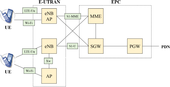
Figure 11.1. Functional architecture for LTE and Wi-Fi carrier aggregation
The eNB entity is the anchor point for the data exchanged with the mobile, belonging to the user plane (the IP packets) and the control plane and connects to the EPC network:
- – at the level of the mobility management entity (MME), via the S1-MME interface, for the S1-AP signaling;
- – at the level of the serving gateway (SGW), via the S1-U interface, for the S1bearer.
11.2. Protocol architecture
11.2.1. LWA
At the radio interface LTE-Uu, between the mobile and the eNB entity, the traffic data correspond to IP packets and the signaling data relate to RRC (Radio Resource Control) messages exchanged between the mobile and the eNB entity and NAS (Non-Access Stratum) messages exchanged between the mobile and the MME entity.
The traffic and signaling data is encapsulated by the data link layer, broken down into three sub-layers:
- – packet data convergence protocol (PDCP);
- – radio link control (RLC);
- – medium access control (MAC).
LWA (LTE/WLAN Aggregation) occurs at the PDCP layer. The entity eNB carries out a switching of the bearers between, on the one hand, the S1 bearers and, on the other hand (Figures 11.2 and 11.3):
- – the LTE bearer, for which the data transits only on the LTE access;
- – the shared LWA bearer, for which the data can pass on both LTE and Wi-Fi accesses;
- – the switched LWA bearer, for which the data only passes over the Wi-Fi access.
The LWA bearer is controlled by the eNB entity from measurement reports transmitted by the mobile.
The PDCP frames transmitted over the Wi-Fi access are encapsulated by an LWAAP (LWA Adaptation Protocol) header containing the logical channel identifier (LCID) of the radio bearer.

Figure 11.2. Protocol architecture for LWA aggregation eNB and AP entities are collocated

Figure 11.3. Protocol architecture for LWA aggregation eNB and AP entities are distant
On LTE access, the LCID is carried by the MAC layer. The recipient uses the LCID to reassemble the PDCP frames of the same bearer.
The re-sequencing of the PDCP frames received by the two LTE and Wi-Fi accesses is performed by the PDCP.
Frames transported on an LWA bearer are only those acknowledged and those corresponding to RLC frames using acknowledgment mode (AM) on the LTE interface.
The Type field of the LLC header for Wi-Fi access is set to hexadecimal 9E65. The mobile uses this value to determine that the frame comes from an LWA bearer.
When the eNB and AP entities are distant, the eNB entity can be connected to multiple AP entities via the Xw interface that supports the traffic and control data (Figure 11.3).
The NAS signaling data is carried on the S1-MME interface, between the MME and eNB entities, and then on the Xw-C (Control) interface, between the eNB and AP entities.
Traffic data, corresponding to the IP stream, is transported in a GTP-U (GPRS Tunneling Protocol User) tunnel:
- – on the S1-U interface, between SGW and eNB entities;
- – on the Xw-U (User) interface, between the eNB and AP entities.
Mutual authentication is based on the EAP-AKA (Authentication and Key Agreement) method described in Chapter 6.
During the procedure of attaching the mobile to the 4G mobile network, the home subscriber server (HSS) retrieves the Ki key allocated to the mobile, draws a random (RAND) and calculates the integrity key (IK) and cipher key (CK).
The Ki key is a secret key, shared between the HSS entity and the mobile, created during the subscription.
The HSS entity computes the KASME key from the IK and CK and passes the KASME key and the random to the mobility management entity (MME).
From the KASME key, the MME entity calculates the KeNB key and transmits it to the eNB entity.
The MME entity transmits the random (RAND) to the mobile that performs the same operations to generate the KeNB key.
The pairwise master key (PMK) used for the four-way handshake procedure is the S-KWT key derived from the KeNB key.
11.2.2. LWIP aggregation
The LWIP (LTE/WLAN radio level integration with IPsec tunnel) aggregation only applies to IP packets of the S1 bearer. The RRC (Radio Resource Control) and signaling messages, which are exchanged between the mobile and the eNB entity, are carried on the LTE interface (Figure 11.4).

Figure 11.4. Protocol architecture for LWIP aggregation
IP packets are transported between the eNB entity and the mobile in the LWIP tunnel. The LWIPEP (LWIP Encapsulation Protocol) header contains the LCID of the radio bearer.
The LWIP tunnel is protected between the mobile and the security gateway (SeGW) through an IP Security (IPSec) mechanism. Only one IPSec mechanism is mounted for all LWIP tunnels.
The LWIP tunnel is transmitted in a GTP-U tunnel on the Xw interface, between the eNB and the SeGW entities.
The IKE procedure for the IPSec mechanism is initialized after the association of the mobile to the Wi-Fi access point and authentication based on the EAP-AKA method.
Each bearer is configured so that the downstream direction or the upstream direction or both directions of transmission pass through the tunnel protected by the IPSec mechanism.
For the downstream, IP packets are transmitted either on the LTE interface only, or on the Wi-Fi interface only, or simultaneously on both LTE and Wi-Fi interfaces. In the latter case, the mobile can receive IP packets not in sequence.
For the upstream, IP packets are transmitted either on the LTE interface only, or on the Wi-Fi interface only.
11.2.3. LAA aggregation
LAA (Licensed Assisted Access) aggregation consists of using the 5-GHz U-NII (Unlicensed-National Information Infrastructure) band to transmit a 3GPP compliant LTE signal.
The radio channel operating in the licensed band, used as the primary channel, supports control plane (signaling) and traffic plane (IP packets).
The radio channel operating in the U-NII band, used as a secondary channel, supports only the data of the traffic plane.
11.3. Procedures
11.3.1. LWA
11.3.1.1. WT Addition procedure
The WT Addition procedure is initialized by the eNB entity and is used to establish the mobile context at the AP to provide mobile resources over the Wi-Fi interface (Figure 11.5).
- 1) The eNB entity transmits to the access point (AP) the message Xw-AP WT Addition Request in order to allocate resources to the mobile, indicating the characteristics of the LWA bearer.
- 2) If the access point can accept the resource request, it responds with the message Xw-AP WT Addition Request Acknowledge.
- 3) The eNB entity sends the message RRC ConnectionReconfiguration to the mobile, indicating the configuration of the radio resource.
- 4) The mobile applies the new configuration and responds to the eNB entity with the message RRC ConnectionReconfigurationComplete.
- 5) The mobile associates with the access point, which then transmits the message Xw-AP WT Association Confirmation to the eNB entity.

Figure 11.5. WT Addition procedure
11.3.1.2. WT Modification procedure
The WT Modification procedure can be initialized either by the eNB entity or by the access point and can be used to modify, set or release bearer contexts or to modify other properties of the mobile context.
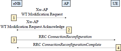
Figure 11.6. WT Modification procedure initiated by the eNB entity
The WT Modification procedure initiated by the eNB entity is described in Figure 11.6.
- 1) The eNB entity sends the message Xw-AP WT Modification Request to request the AP to modify the specific bearer resources.
- 2) If the access point accepts the request, it applies the configuration modification to the resource and responds with the message Xw-AP WT Modification Request Acknowledge.
- 3) If the modification requires a new configuration for the mobile, the eNB entity sends the message RRC ConnectionReconfiguration, including the new configuration of the Wi-Fi radio resource.
- 4) The mobile applies the new configuration and responds with the message RRC ConnectionReconfigurationComplete.
The WT Modification procedure initiated by the access point is described in Figure 11.7.
- 1) The access point sends the message Xw-AP WT Modification Required to the eNB entity to modify the radio resources of the Wi-Fi access.
- 2) The eNB responds with the message Xw-AP WT Change Confirm.
- 3) If the modification requires a new configuration for the mobile, the eNB entity sends the message RRC ConnectionReconfiguration, including the new configuration of the Wi-Fi radio resource.
- 4) The mobile applies the new configuration and responds with the message RRC ConnectionReconfigurationComplete.

Figure 11.7. WT Modification procedure initiated by the access point
11.3.1.3. WT Release procedure
The WT Release procedure can be initialized either by the NB entity or by the access point and is used to initiate the release of the mobile context at the access point. The recipient cannot reject the request.
The WT Release procedure initiated by the eNB entity is described in Figure 11.8.
- 1) The eNB entity sends the message Xw-AP WT Release Request to request the Wi-Fi access point to release the allocated radio resources over the Wi-Fi access.
- 2) If necessary, the eNB entity sends the message RRC ConnectionReconfiguration to the mobile indicating the release of the radio resources.
- 3) The mobile responds with the message RRC ConnectionReconfigurationComplete.

Figure 11.8. WT Release procedure initiated by the eNB entity
The WT Release procedure initiated by the access point is described in Figure 11.9.
- 1) The access point sends the message Xw-AP WT Release Required to the eNB entity to request the release of radio resources from the Wi-Fi access.
- 2) The eNB entity responds with the message Xw-AP WT Release Confirm.
- 3) If necessary, the eNB entity sends the message RRC ConnectionReconfiguration to the mobile indicating the release of the radio resources.
- 4) The mobile responds with the message RRC ConnectionReconfigurationComplete.

Figure 11.9. WT Release procedure initiated by the access point
The procedure for changing the access point is initiated by the eNB entity and used to transfer the mobile context from a source AP to a target AP. This procedure is performed using the WT Release and WT Addition procedures.
11.3.2. LWIP aggregation
The procedure for establishing the LWIP and IPSec tunnels is described in Figure 11.10.
- 1) The eNB entity configures the mobile with the message RRC ConnectionReconfiguration to perform measurements on Wi-Fi access in order to start the LWIP and IPSec tunnels establishment.
- 2) The mobile applies the new configuration and responds with the message RRCConnectionReconfigurationComplete.
- 3) The mobile sends to the eNB entity the message RRC WLANMeasurements containing the measurements performed on the Wi-Fi access.
- 4) The eNB entity sends the message Xw-AP LWIP Addition Request to request the security gateway (SeGW) to allocate resources for IPSec tunnel establishment.
- 5) If the security gateway accepts the request, it responds with the message Xw-AP LWIP Addition Request Acknowledge.
- 6) The eNB entity sends the message RRC ConnectionReconfiguration to the mobile to establish the LWIP tunnel.
- 7) The mobile applies the new configuration and responds with the message RRC ConnectionReconfigurationComplete.
- 8) The mobile sends the confirmation of the association with the Wi-Fi access point to the eNB entity in the message RRC WLANConnectionStatusReport.
- 9) The eNB entity sends the message RRC ConnectionReconfiguration to the mobile to establish the IPSec tunnel and can configure the bearers that will use the IPSec tunnel.
- 10) The mobile applies the new configuration and responds with the message RRC ConnectionReconfigurationComplete.

Figure 11.10. LWIP and IPSec tunnel establishment
11.3.3. LAA aggregation
The access mechanism to the radio channel is different for the LTE and Wi-Fi interfaces.
For the LTE radio interface, access to the radio channel is controlled by the eNB entity.
For the Wi-Fi radio channel, access to the radio channel uses the CSMA/CA (Carrier Sense Multiple Access/Collision Avoidance) mechanism.
The eNB entity or the mobile applies the LBT (Listen Before Talk) mechanism before transmitting in the U-NII radio channel.
The equipment uses energy sensing to determine the presence or absence of other signals on the radio channel during the CCA (Clear Channel Assessment) observation time.
The LBT mechanism has two options: frame-based equipment (FBE) and load-based equipment (LBE).
For the FBE option, the equipment operates on the basis of a synchronization with a fixed frame period.
At the end of the frame period, the equipment performs a CCA check on the radio channel. If the channel is free, then the data is transmitted immediately to the beginning of the next frame. If the channel is busy, then another CCA check is performed at the next frame period (Figure 11.11).

Figure 11.11. LBT mechanism –FBE option
For the LBE option, the device performs CCA control whenever there is data to transmit. If the channel is free, then the data is transmitted immediately. If the channel is busy, then the device must wait until the timer for the backoff mechanism expires (Figure 11.12). This timer is decremented when the radio channel is free.

Figure 11.12. LBT mechanism –LBE option
The LBE option is relatively similar to the backoff mechanism of Wi-Fi access. Unlike Wi-Fi access, which adopts an exponential backoff mechanism, the LBE option opts for a backoff mechanism with a fixed window.
11.4. PDCP
The Packet Data Convergence Protocol (PDCP) is used for RRC (Radio Resource Control) messages, relating to dedicated control data, and IP (Internet Protocol) packet related to the traffic.
The PDCP performs the following functions:
- – compression of traffic data headers using the ROHC (Robust Header Compression) mechanism;
- – security of traffic data (confidentiality) and of RRC messages (integrity and confidentiality);
- – delivery in sequence of RRC messages and IP packets;
- – recovery of PDCP frames lost during the handover.
The PDCP defines headers to encapsulate the RRC signaling data, the traffic data and the control messages associated with the traffic data.
The structure of PDCP frames is described in Figure 11.13 for frames containing traffic data and RRC signaling data.

Figure 11.13. PDCP frame structure containing IP packets or RRC messages
PDCP SN: this field is coded on five bits for the RRC signaling data and on seven or 12 bits for the traffic data. It indicates the sequence number of the PDCP frame. This sequence number makes it possible to recover the PDCP blocks lost during the handover. For LWA, this field allows the data received from LTE and Wi-Fi access to be put in order.
MAC-I: this field is coded on four bytes. It contains the seal for controlling the integrity of the PDCP frame containing RRC signaling data.
D/C (Data/Control): this bit indicates whether the frame contains traffic data (bit to ONE) or control messages specific to the PDCP (bit to ZERO).
The structure of the PDCP frames is described in Figure 11.14 for frames containing control messages of the PDCP layer.

Figure 11.14. PDCP frame structure containing Status Report messages
PDU (Packet Data Unit) Type: this field is coded on three bits. It indicates the type of control message associated with the traffic data:
- – Status Report message (value 000) is used differently for LTE access and Wi-Fi access. For LTE access, during the recovery procedure following a cell change, it indicates a list of PDCP frame numbers not received during the handover. For Wi-Fi access, it provides error statistics;
- – ROHC Feedback message (value 001) is related to the compression mechanism of the headers.
FMS (First Missing): this field is coded on 12, 15 or 18 bits. It contains the first sequence number of the missing PDCP frames.
Bitmap: this field is a collection of bits indicating whether the PDCP frame was received correctly (bit to ONE) or not (bit to ZERO). The most significant bit of the first byte represents the sequence number following the value of the FMS field.
HRW (Highest Received PDCP SN on WLAN): this field is coded on 12, 15 or 18 bits. It contains the highest value of the PDCP SN parameter of the PDCP frame received on the Wi-Fi interface.
NMP (Number of Missing PDCP SDUs): this field is coded on 12, 15 or 18 bits. It contains the number of missing frames from and including the value corresponding to the FMS parameter up to the value of the HRW parameter.