
12
MPTCP Aggregation
12.1. Functional architecture
In the case of LWA/LWIP aggregation solutions, the LTE (Long-Term Evolution) and Wi-Fi access aggregation is done at the eNB entity level. In MPTCP-based (Multi-Path Transmission Control Protocol) aggregation solutions, aggregation occurs at the TCP layer.
The target of MPTCP aggregation is to transmit data using multiple paths without causing modifications to existing infrastructures (the 4G mobile network, Wi-Fi access).
The MPTCP connection is performed by the MPTCP client hosted in the mobile and the MPTCP server hosted in an MPTCP proxy. The MPTCP connection is built on TCP connections, each corresponding to an access, LTE or Wi-Fi (Figure 12.1).

Figure 12.1. Architecture for MPTCP aggregation
12.2. TCP
The TCP (Transmission Control Protocol) is a reliable protocol for the following reasons:
- – data transmission is conditional upon the establishment of a connection between the source and destination;
- – the receiver delivers ordered, error-free data to the application layer;
- – the receiver implements a source flow control mechanism based on its receive buffer occupancy;
- – the source rate is regulated based on the congestion state of the network.
The TCP is byte-stream oriented:
- – at the source side, the application writes bytes into the transmission buffer. The TCP transmits segments to the recipient;
- – at the destination side, the application reads bytes into the reception buffer. The application is in charge of delimiting messages.
12.2.1. TCP header
The TCP header is described in Figure 12.2 and contains the following fields:
Source Port and Destination Port: these fields identify the port numbers of the source and destination applications.
Sequence Number: this field specifies the current number assigned to the first octet of the data encapsulated by the TCP header. Each byte of the message encapsulated by the TCP header consumes a number.
Acknowledgment Number: this field contains the next sequence number expected by the transmitter of this acknowledgment. It implicitly acknowledges the previous numbers.
Data Offset: this field indicates the number of 32-bit words in the TCP header. Taking into account the presence of the Option field, this field indicates the starting point of the data encapsulated by the TCP header.
Reserved: this field is reserved for later use.
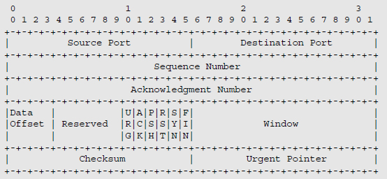
Figure 12.2. Format of TCP header
Flags:
- – URG bit is set to ONE if the Urgent Pointer field is being used;
- – ACK bit is set to ONE to indicate the validity of the Acknowledgment Number. When the ACK bit is set to ZERO, the segment does not contain an acknowledgment and the Acknowledgment Number field is ignored;
- – PSH bit is set to ONE to notify the recipient to deliver the data to the respective application without buffering;
- – RST bit is set to ONE to allow a connection to be reset; it is also used to refuse an attempt to open a connection;
- – SYN bit is set to ONE to establish a connection;
- – FIN bit is set to ONE to a connection.
Window: this field specifies the window size. The amount of data that the receiver of the segment is able to receive is mentioned in each segment. This field enables flow control to be performed. The receiver may respond with a zero-valued Window field. This indicates that its reception buffer is full.
Checksum: this field is used to detect whether bit errors occurred during transfer. This check encompasses the header, the data encapsulated by the TCP header and a pseudo-header. The pseudo-header includes the source and destination IP addresses, the Protocol field from the IP header and the length of the IP packet.
Urgent Pointer: this field points to the first byte where urgent data can be found. It allows the sender to transmit information to the receiver without interrupting the message transmission in progress.
Options: this field may be used for various functions:
- – maximum segment size (MSS): this information is only provided during the connection opening procedure. With an MTU of 1,500 bytes over Ethernet, the MSS is 1,460 bytes in IPv4 and 1,440 bytes in IPv6;
- – sizing of the reception buffer (Window Scale): the sender and receiver may negotiate a scale factor for the window size. This option makes it possible to circumvent the limitation in window size due to the 16-bit length of the Window field;
- – selective acknowledgment (SACK) instead of a bulk retransmission: the receiver may request retransmission of one or more specific segments. After obtaining them, it can then acknowledge all the buffered data. This option provides two pointers to indicate each received data block.
12.2.2. Opening and closing a connection
Opening a connection involves the following three steps:
- – the client sends a segment having a SYN bit set to ONE and an ACK bit set to ZERO. The client indicates the sequence number X;
- – the server responds with the SYN bit set to ONE and the ACK bit set to ONE. The server indicates the sequence number Y. The server validates the received segment by indicating the next expected byte X + 1;
- – the client responds with the SYN bit set to ONE and the ACK bit set to ONE. The client indicates the sequence number X and validates the received segment by indicating the next expected byte Y + 1.
An endpoint can close the connection using either the FIN bit or the RST bit. The FIN bit allows the connection to be closed when the data to be transferred have actually been received by the recipient. The RST bit is used to close the session abruptly.
12.2.3. Data transfer
The TCP has the Sequence Number, Acknowledgment Number and Checksum fields to perform error-free data transfer. At the time a segment is transmitted, a retransmission timeout (RTO) is initiated.
If the segment is acknowledged before the expiration of the timer, then the latter is stopped. On the other hand, if the timer expires before the acknowledgment arrives, then the segment is retransmitted and the timer is activated again.
When a segment is retransmitted, the retransmission timer is not updated, its value being doubled instead.
In a standard configuration, retransmission resumes from the segment for which the timer expired, since the sender has no information as to whether or not the next segments were actually received, unless the SACK option is used.
The TCP continuously adjusts the value of this retransmission timer. It manages an RTT (Round Trip Time) variable, which is the current estimate of the time elapsed between the transmission of a segment and the reception of the acknowledgment.
12.2.4. Slow Start and Congestion Avoidance mechanisms
The source takes advantage of the Slow Start and Congestion Avoidance mechanisms to control the amount of transmitted data. These mechanisms are implemented using two variables:
- – the congestion window (cwnd) indicates the amount of bytes the source can transmit before it receives an acknowledgment via the Acknowledgment Number field;
- – the receive window (rwnd) indicates the amount of bytes the receiver is ready to receive, a value indicated via the Window field.
On establishing the connection, the sender initializes the congestion window (cwnd) with a value equal to two segments of maximum length (MSS) (Figure 12.3). If the segments are acknowledged before the expiration of the timer, the size of the congestion window is doubled. Each successful transmission thus enables the size of the congestion window to be doubled.
The Congestion Avoidance mechanism introduces a new variable: the congestion avoidance threshold (ssthresh) (Figure 12.3). When the congestion avoidance threshold is reached, the congestion window grows linearly by an increment corresponding to the maximum size of one segment.

Figure 12.3. Slow Start and Congestion Avoidance mechanisms
In the beginning, the value of the congestion avoidance threshold is equal to half that of the receive window (rwnd). If the timer expires before receiving the acknowledgment for the transmitted data, then the congestion avoidance threshold is then set to half the current congestion window and the Slow Start mechanism restarts.
12.2.5. Fast Retransmit and Fast Recovery mechanisms
The Fast Retransmit mechanism enables the sender to retransmit a segment without waiting for the timer to expire, thus avoiding the start-up of the Slow Start mechanism (Figure 12.4).
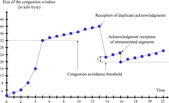
Figure 12.4. Fast Retransmit and Fast Recovery mechanisms
If a segment is missing at the receiver, then the latter will emit segments with duplicate acknowledgments, having the same value in the Acknowledgment Number field.
At the other end, the reception of duplicate acknowledgments is used to determine the missing segment. It should be noted that the reception of duplicate acknowledgments may also be caused by network-induced desequencing. When three duplicate acknowledgments are received, the sender resends the missing segment.
The Fast Recovery mechanism operates as follows:
- – when three duplicate acknowledgments are received, the congestion avoidance threshold (ssthresh) is set to half the current congestion window;
- – the congestion window (cwnd) takes on a value greater than the congestion avoidance threshold by three MSS values;
- – for every additional duplicate acknowledgment received, the congestion window is incremented by one MSS value;
- – at the first acknowledgment corresponding to the retransmitted segments, the congestion window is positioned at the congestion avoidance threshold.
12.2.6. ECN mechanism
WRED (Weighed Random Early Discard) queue management is a method of giving the recipient an indication of congestion. It is based on the anticipated and random destruction of packets.
The ECN (Explicit Congestion Notification) mechanism constitutes another method to provide such a congestion indication without destroying packets. It is based on the use of fields in the header of the IP and TCP to warn terminal stations about the beginning of congestion.
The ECN mechanism uses two bits in the IP header (Figure 12.5). These two bits complement the six bits in the DSCP (DiffServ Code Point) field.

Figure 12.5. ECN field in IP header
When these two bits equal 10 or 01, they indicate that the source and the destination are able to treat the ECN mechanism. These two bits are called ECT (ECN-Capable Transport, ECT(0) and ECT(1) respectively). Both endpoints are made aware of each other’s ability to treat the ECN mechanism during the TCP connection procedure (Table 12.1).
Table 12.1. ECN field in IP header
| ECN field | Designation | |
| 0 | 0 | Non-ECT |
| 0 | 1 | ECT(1) |
| 1 | 0 | ECT(0) |
| 1 | 1 | CE |
When these two bits equal 00, they indicate that the source and the destination are not able to treat the ECN mechanism (Table 12.1).
When the router detects the beginning of congestion through the WRED queue management mechanism, the two bits assume the value 11 (Table 12.1). These two bits are called CE (Congestion Experienced).
The ECN field only assumes the CE value if this field previously had the value ECT(0) or ECT(1) or if this field was already flagged as CE. Should the ECN field equal 00, the detection of incipient congestion would result in packet destruction. The CE value is used by the router to notify the recipient of congestion onset.
The ECN mechanism further comprises two bits in the TCP header (Figure 12.6). These two bits complement the six flag bits.
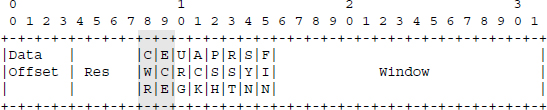
Figure 12.6. ECN field in TCP header
The ECE bit (ECN-Echo) is exploited by the recipient to warn the source that a beginning of congestion has been detected in the network. This bit is set when the recipient receives a packet whose ECN field in the IP header has the CE value.
The CWR (Congestion Window Reduced) bit is used by the source to notify the recipient that it has indeed received the ECE flag. When the recipient receives the CWR flag, it stops transmitting the ECE flag.
While the TCP connection is being opened, the client sends a TCP header with the SYN (connection opening), ECE and CWR flags set to one. The server responds with a TCP header, wherein the SYN (connection opening) and ECE flags are set to one. During that stage, the ECE and CWR bits are used to indicate the ability of terminals to treat the ECN mechanism, rather than the occurrence of congestion in the network.
12.3. MPTCP
The MPTCP connection consists of a combination of several TCP connections, with each TCP connection transmitted on a path to appear as a normal connection for the different devices crossed:
- – each TCP connection must start with the establishment procedure;
- – each TCP connection must independently manage its sequence number;
- – each TCP connection must end with FIN or RST flag.
The MPTCP uses the Kind (= 30) option of the TCP header, with each MPTCP message being identified by the Subtype field (Figure 12.7).

Figure 12.7. Format of MPTCP option
Table 12.2 summarizes the different MPTCP options corresponding to the Subtype field.
Table 12.2. MPTCP options
| Value (in hexadecimal) | Designation |
| 00 | MP_CAPABLE |
| 01 | MP_JOIN |
| 02 | DSS |
| 03 | ADD_ADDR |
| 04 | REMOVE_ADDR |
| 05 | MP_PRIO |
| 06 | MP_FAIL |
| 07 | MP_FASTCLOSE |
12.3.1. Establishment of MPTCP connection
The establishment of MPTCP connection begins with an exchange SYN, SYN/ACK, ACK of the first TCP connection. Each TCP header contains the MP_CAPABLE option. This option declares that the sender is capable of rolling MPTCP over the first TCP connection (Figure 12.8).
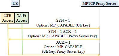
Figure 12.8. Establishment of an MPTCP connection
This option is used to declare the 64-bit key that each entity (the mobile, the Proxy Server MPTCP) has generated for this MPTCP connection. This key will later authenticate the addition of new TCP connections to this MPTCP connection.
This is the only time that the key will be sent clearly on the first TCP connection, with the exception of the MP_FASTCLOSE option. All future TCP connections will identify the connection using a 32-bit token. This token is a cryptographic hash of this key.
12.3.2. Adding a TCP connection
When the MPTCP connection is established with the MP_CAPABLE exchange on the LTE access, a new TCP connection can be added for the Wi-Fi access.
The new TCP connection starts with a normal exchange SYN, SYN/ACK, ACK. The MP_JOIN option is used to identify the new TCP connection (Figure 12.9).
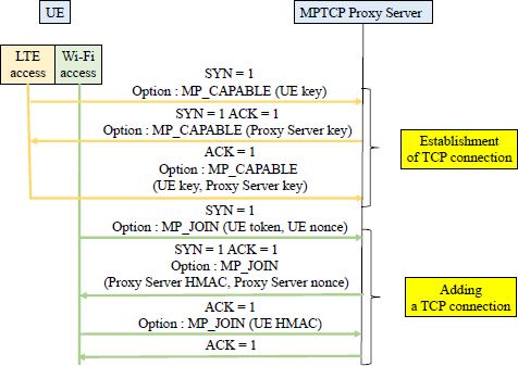
Figure 12.9. Adding a TCP connection
The mobile transmits the SYN flag in the first TCP header whose MP_JOIN option contains a token and a random number (nonce).
The token is a cryptographic hash generated from the key of the MPTCP Proxy Server. It is used by the MPTCP Proxy Server to identify the MPTCP connection.
The random number (nonce) is used to calculate the HMAC authentication of the following headers:
The MPTCP Proxy Server responds with the SYN/ACK flags in the TCP header whose MP_JOIN option contains HMAC (Proxy Server) authentication and a random number (nonce):
- HMAC (Proxy Server) = HMAC (Key, Message)
- Key = Proxy Server key+ mobile key
- Message = nonce (Proxy Server) + nonce (mobile)
The mobile performs the third exchange with the ACK flag in the TCP header whose MP_JOIN option contains HMAC (mobile) authentication:
- HMAC (mobile) = HMAC (Key, Message)
- Key = mobile key + Proxy Server key
- Message = nonce (mobile) + nonce (Proxy Server)
The Proxy Server MPTCP terminates the procedure with the ACK flag in the TCP header to acknowledge the TCP header received during the third exchange.
Each MP_JOIN option contains an address identifier. The address identifier has only a meaning in a single connection, where it identifies the source IP address of this packet, even if this IP address has been modified by an intermediate device (e.g. by the NAT function).
Hosts can specify in the MP_JOIN option when configuring a TCP connection whether they want the TCP connection to be used as a normal path or as a backup path. The host may request a change in the priority of the connection via the MP_PRIO option.
12.3.3. Data transfer
The DSS (Data Sequence Signal) option provides control information to enable the reassembly of streams from different TCP connections and its reliable and orderly delivery of data for the application at the destination level.
To deliver the data in sequence, the DSS option contains the mapping between the data sequence number (DSN) of the MPTCP connection and the sub-flow sequence number (SSN) of the TCP connection (Figure 12.10).
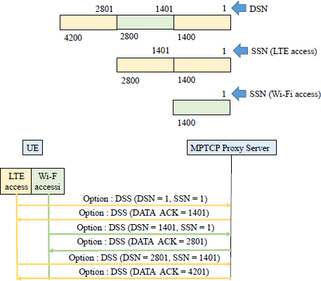
Figure 12.10. Data transfer
The DSS option uses the Data ACK field to acknowledge data from the MPTCP connection. This acknowledgment indicates to the sender that the data corresponding to the DSN number has been received and specifies the next DSN to be transmitted.
For a normal TCP connection, the recipient of a segment notifies the source of the available size for the receive memory in the Window field.
The MPTCP connection uses a single receive window for all TCP connections, which allows each TCP connection to transmit data if the size of the receive memory allows.
The value of the receive window is indicated in the Window field of the TCP connection, whose associated DSS option contains in the DATA_ACK field the number of the next expected byte relative to the DSN sequence (Figure 12.10). The source can transmit on all TCP connections segments whose DSN number is between DATA_ACK and DATA_ACK + Window.
For a normal TCP connection, congestion control introduces another limitation provided by the congestion window (cwnd).
Executing the existing algorithms independently for each TCP connection would give very high flow rate for MPTCP connection if these TCP connections cross a single bottleneck.
In addition, it is desirable for a source with multiple available accesses to use the least congested path.
The congestion control algorithm applies only to the increase phase of the reception window. For this, it is necessary to couple the congestion control algorithms operating on the different TCP connections and dynamically control the overall aggressiveness of the MPTCP connection.
The Slow Start, Fast Retransmit and Fast Recovery mechanisms are the same as for the standard TCP.
When a retransmission over a TCP connection fails, the sender can send the data from the MPTCP connection with the same DSN sequence number to another TCP connection after a timeout.
During a retransmission, the host must, however, try to retransmit the original data over the original TCP connection, in order to preserve the integrity of the SSN sequence numbers.
12.3.4. Closing an MPTCP connection
When an application requests the closing of a session, it indicates that it no longer has data to send. For a TCP connection, this causes the FIN flag to be issued. For an MPTCP connection, an equivalent mechanism is required, based on the DATA_FIN indication contained in the DSS option (Figure 12.11).
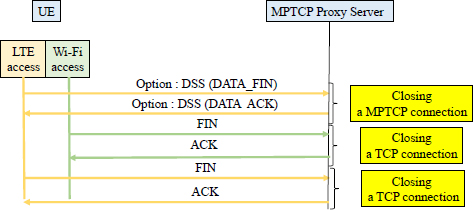
Figure 12.11. Closing a MPTCP connection
The closure of the MPTCP connection is decoupled from the closures of the TCP connections. When DATA_FIN has been acknowledged, all remaining TCP connections must be closed with exchanges of the FIN flag. The DATA_FIN indication is acknowledged when all data has been transferred to the different TCP connections.
The TCP connection has the means to close a connection with the RST flag abruptly. The option MP_FASTCLOSE allows the same function to be performed for the MPTCP connection (Figure 12.12).

Figure 12.12. Abrupt closure of MPTCP connection
Host A (e.g. the proxy server) sends, over a TCP connection, a TCP header containing the MP_FASTCLOSE option, containing the key of host B (for example the mobile) declared during the establishment of the MPTCP connection. For all TCP connections, host A sends the RST flag.
On receipt of the MP_FASTCLOSE option containing the valid key, host B responds on the same TCP connection with the RST flag and closes the other TCP connections.
12.3.5. Adding and removing an address
An MPTCP connection is initially configured between the A1 pair (address/port for LTE access) of host A (the mobile) and the B1 pair (address/port) of host B (the proxy server). Host A can start an additional TCP connection from its A2 pair (Wi-Fi access) by sending the SYN flag and the MP_JOIN option.
At the end of the first TCP connection, host A uses the ADD_ADDR option, informing the recipient of the A2 pair (address/port).
Each IP address is associated with a unique address identifier (address ID) that can be used for address removal or for the MP_JOIN option.
Due to the proliferation of NAT devices, it is likely that a host might attempt to publish private IP addresses. The MP_JOIN procedure for creating a new TCP connection provides mechanisms to minimize security risks.
Similarly, host B can use the ADD_ADDR option to inform host A of the availability of the B2 pair (address/port).
From the point of view of host A (the mobile), the following four TCP connections can thus be opened:
- address/port A1 and address/port B1, on LTE access;
- address/port A1 and address/port B2, on LTE access;
- address/port A2 and address/port B1, on Wi-Fi access;
- address/port A2 and address/port B2, on Wi-Fi access.
If during an MPTCP connection, a previously advertised address becomes invalid, then the affected host must advertise it in the REMOVE_ADDR option so that the other end can delete the TCP connections bound to that address.
12.3.6. Return to the TCP connection
At the beginning of an MPTCP connection, it is important to ensure that the path is fully compatible with the MPTCP options. If any of the SYN flags do not have the MPTCP options, the session must continue automatically on a regular TCP connection.
This scenario occurs when the host does not process MPTCP options or when intermediate devices prohibit the use of options.
In the case where the data is not contiguous, which could happen when a single TCP connection retransmits data from another recently closed TCP connection, the recipient must close the TCP connection with the RST flag and the MP_FAIL option. The recipient must reject all data that follow the specified DSN sequence number. The source may try to restart the TCP connection.