
The analogy can be made that microphones are to audio production what colors are to painting. The more colors and hues available to a painter, the greater the possibilities for coloration on a visual canvas. In recording sound, the more models of microphones, the greater variety of tones on the sonic palette and, hence, the greater the possibilities for coloration in designing an aural canvas.
When choosing a microphone, or mic, consider three basic features: operating principles, directional characteristic(s), and sound response. Appearance may be a fourth feature to consider if the mic is on-camera. Cost and durability may be two other considerations.
Like the loudspeaker, the microphone is a transducer—a device that converts one form of energy into another—but it works in the opposite direction: Instead of changing electric energy into acoustic energy as the loudspeaker does, it changes acoustic energy into electric energy. The electric energy flows through a circuit as voltage.
In measuring an electric circuit, a foremost concern is impedance—that property of a circuit, or an element, that restricts the flow of alternating current (AC). Impedance is measured in ohms (ω), a unit of resistance to current flow. The lower the impedance, the better. Microphones used in professional audio are low impedance. Low-impedance microphones and equipment have three advantages over high-impedance mics: They generate less noise, they are much less susceptible to hum and electrical interference such as static from motors and fluorescent lights, and they can be connected to long cables without increasing noise. Professional mics usually range in impedance from 150 to 600 ohms.
The device that does the transducing in a microphone is mounted in the mic head and is called the element. Each type of mic gets its name from the element it uses. The elements in professional microphones operate on one of two physical principles: magnetic induction and variable capacitance.
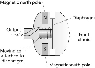
Magnetic induction uses a fixed magnet and a movable diaphragm to which a small, lightweight, finely wrapped coil suspended between the poles of a fixed magnet is attached. When it moves through the magnetic field in response to the sound waves hitting the diaphragm, it produces voltage proportional to the sound-pressure level. Such mics are called moving-coil microphones (see Figure 6-1).
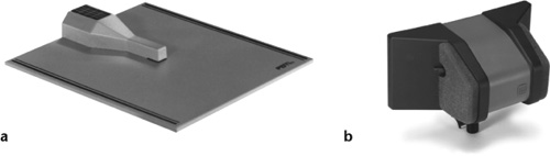
Another type of mic employing magnetic induction is the ribbon microphone (see Figure 6-2). Instead of a moving coil, it uses a metal ribbon attached to a fixed magnet. As the ribbon vibrates from the pressure of the sound waves, voltage is generated. Generally, in the earlier generations of ribbon mics, the ribbon is situated vertically; in many modern ribbon mics, it is positioned horizontally. The longitudinal positioning and the more advanced ribbon design have helped make it possible to house modern ribbon mics in smaller, lighter-weight casings than the older ribbon mics (see Figure 6-3).
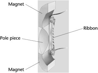
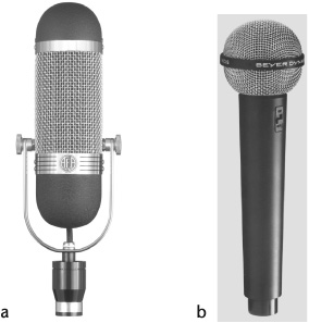
Figure 6-3. Ribbon microphones. (a) Traditional model with vertical ribbon. (b) Newer model with small, longitudinal ribbon.
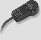
Active ribbon microphones use an amplifier system, which requires phantom power; passive microphones do not require phantom power. Phantom power is a method of remotely powering an amplifier or impedance converter by sending voltage along the audio cable (see “Variable Capacitance” later in this chapter). Among the advantages of the active ribbon microphone over conventional ribbons are higher output and sensitivity, wider and flatter frequency response, and the ability to handle higher sound levels before distortion (see “General Transducer Performance Characteristics” later in this chapter).
Mics that use the magnetic induction principle are classified as dynamic microphones. This includes the moving-coil and ribbon transducers. In practice, however, the moving-coil mic is referred to as a dynamic mic and the ribbon as a ribbon mic; the term moving coil is seldom used when referring to a dynamic mic. To avoid confusion, however, the term moving coil, instead of dynamic, is used throughout this book.
Microphones operating on the variable capacitance principle transduce energy using voltage (electrostatic) variations instead of magnetic (electromagnetic) variations and are called capacitor microphones. They are also referred to as condenser microphones, a holdover from the past.
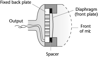
The element consists of two parallel plates separated by a small space (see Figure 6-4). The front plate is a thin, metalized plastic diaphragm—the only moving part in the mic head—and the back plate is fixed. Together, these plates or electrodes form a capacitor—a device that is capable of holding an electric charge. As acoustic energy moves the diaphragm back and forth in relation to the fixed back plate, the capacitance change causes a voltage change, varying the signal. The signal output is delicate and has a very high impedance, however, and requires a preamplifier (mounted near the mic capsule) to bring it to useable proportions.
Most preamps in capacitor microphones use a transistor circuit, which generally produces a clean sound. But a number of capacitor mics use a tube circuit in the preamp instead. This is due to the particular sonic characteristic that tube microphones give to sound, which many perceive as more present, livelier, more detailed, and not as colored as the transistorized capacitors.
Because the capacitor requires polarizing voltage and the preamplifier requires power voltage to operate, capacitor microphones must have a separate power source either from batteries contained inside the mic or from an external, or phantom, power supply. External power eliminates the need for batteries and may be supplied from the console, studio microphone input circuits, or portable units.
Some capacitor microphones have an electret diaphragm. An electret is a material (high-polymer plastic film) that can hold a charge permanently, eliminating the need for external polarizing voltage. Because only a small battery is required to power the preamp, electret microphones can be made more compact, which facilitated the design of lavaliere and mini-mics.
Each type of microphone is unique. It is not a matter of one microphone being better than another but that one mic may be more suitable for a particular application. Moving-coil microphones are rugged, generate low self-noise, tend to be less susceptible to humidity and wide temperature variations, and handle high sound-pressure levels without distortion. They are usually less expensive than the other professional types and come in a wide variety of makes and models.
The element of a moving-coil mic has more mass than a ribbon or capacitor mic and therefore has greater inertia in responding to sound vibrations. This results in a slower response to transients—sounds that begin with a quick attack, such as a drum hit or breaking glass, and then quickly decay. Capacitor microphones have the lowest mass of the three types of professional mics, which makes them best suited to handle transient sounds. The ribbon mic has relatively low mass; its transient response is between that of the moving-coil mic and the capacitor mic. The inertia of the moving-coil element has another effect on pickup: with increased mic-to-source distance, high-frequency response is reduced. At optimal mic-to-source distances, moving-coil microphones typically color sound more than capacitor mics, usually between 5 kHz and 10 kHz. This tends to add presence, clarity, crispness, or edge to sound.
Ribbon microphones are not widely used today except in music recording and for the speaking voice. They are more expensive than many moving-coil mics and have to be handled with care, particularly when it comes to loud sound levels.
Older ribbon mics have mediocre high-frequency response, which can be turned into an advantage because it gives sound a warm, mellow quality. This attribute complements digital recording which can produce an edged, hard sound quality. Modern ribbon mics have a more extended high-frequency response. As pointed out earlier, compared with most ribbon mics, the active ribbon microphone has a higher output and sensitivity, a wider and flatter frequency response, and the ability to handle higher sound levels before distortion. Generally, ribbon mics have low self-noise, but they also have the lowest output level of the three major types. This means a poorer signal-to-noise ratio if the mic is too far from the sound source or if the cable run is too long.
Capacitor microphones are high-performance instruments. They have a wide, smooth frequency response and reproduce clear, airy, detailed sound with the least amount of tonal coloration compared to moving-coil and ribbon mics. They are the choice among professional-quality mics when it is necessary to accurately capture the true sound of a voice, musical instrument, or sound effect. Capacitor mics have high sensitivity, which makes them the preferred choice for distant miking; high-end response is not hampered by extended mic-to-source distances. They also have the highest output level, which gives them a wide signal-to-noise ratio. These advantages come at a cost—capacitors are generally the most expensive type of microphone, although excellent capacitor models are available at lower prices.
A fundamental rule of good microphone technique is that a sound source should be on-mic—at an optimal distance from the microphone and directly in its pickup pattern. Pickup pattern, formally known as polar response pattern, refers to the direction(s) from which a mic hears sound.
Microphones work in a three-dimensional soundfield; sounds arrive at a mic from all directions. Depending on the design, however, a microphone is sensitive only to sound from all around—omnidirectional, its front and rear—bidirectional, or its front—unidirectional (see Figure 6-5a, b, c). Omnidirectional mics are also called non-directional; and unidirectional mics are also called directional. Cardioid is yet another commonly used name for a unidirectional microphone because its pickup pattern is heart-shaped (see Figure 6-5c). Five unidirectional patterns are in common use: subcardioid (also called wide-angle cardioid), cardioid, supercardioid, hypercardioid, and ultracardioid (see Figure 6-5c, d, e, f).
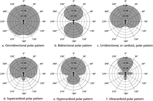
A microphone’s pickup pattern and its transducer classification are unrelated. Moving-coil mics are available in all pickup patterns except bidirectional. Ribbon mics are bidirectional, hypercardioid, or multidirectional—providing more than one pickup pattern. Capacitor mics come in all available pickup patterns, including multidirectional. Figure 6-5 displays basic microphone directionalities. The precise pattern varies from mic to mic.
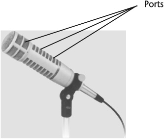
A microphone’s unidirectionality is facilitated by ports at the side and/or rear of the mic that cancel sound coming from unwanted directions. For this reason, you should not cover the ports with a hand or with tape. Directional mics are referred to as single-entry-port microphones, or single-D—having ports in the capsule; or as multiple-entry-port microphones, also called variable-D—having ports in the capsule and along the handle. In a single-entry directional mic, the rear-entrance port handles all frequencies (see Figure 6-6). A multiple-entry directional mic has several ports, each tuned to a different band of frequencies (see Figure 6-7). The ports closer to the diaphragm process the higher frequencies; the ports farther from the diaphragm process the lower frequencies. Ports also influence a mic’s proximity effect, which is discussed later in this chapter.
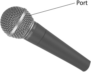
Figure 6-6. Microphone with single entry port. Note: This figure and Figure 6-7 indicate the positions of the ports on these mics. The actual ports are concealed by the mic grille.
A microphone’s directional sensitivity, or polar response pattern, is displayed on a graph. The graph consists of concentric circles, usually divided into segments of 30 degrees. Reading inward, each circle represents a decrease in sound level of 5 dB. The graph depicts response sensitivity in relation to the angle of sound incidence.
The omnidirectional polar pattern shows that sound is picked up almost uniformly from all directions (see Figure 6-5a). The bidirectional polar pattern is most sensitive to sound coming from the front and the rear and least sensitive to sounds entering the sides (see Figure 6-5b).
The cardioid polar pattern illustrates sensitivity to sounds arriving from the front and front-sides (see Figure 6-5c). The subcardioid has a wider front and front-side and therefore a less directional pickup pattern than the cardioid. The supercardioid is more directional at the front than the cardioid (see Figure 6-5d). The hypercardioid polar pattern illustrates its highly directional frontal pickup (see Figure 6-5e).
Here’s a brief comparison of the cardioid, supercardioid, hypercardioid, and ultracardioid pickup patterns: The cardioid mic has a wide-angle pickup of sound in front of the mic and maximum sound rejection at its rear. The supercardioid mic has a somewhat narrower on-axis response and less sensitivity at the rear-sides than the cardioid mic. It has maximum difference between its front- and rear-hemisphere pickups. The hypercardioid mic has a far narrower on-axis pickup and has its maximum rejection at the sides compared with the supercardioid mic. Its rear rejection is poorer than the supercardioid mic, however. The ultracardioid microphone has the narrowest on-axis pickup and the widest off-axis sound rejection of the directional mics (see Figure 6-5f).
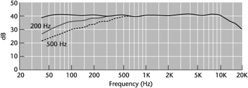
The polar pattern diagrams shown in Figure 6-5 are ideals. In actual use, a microphone’s directional sensitivity varies with frequency. Because treble waves are shorter and bass waves are longer, the higher the frequency, the more directional a mic becomes; the lower the frequency, the less directional a mic becomes, regardless of pickup pattern. Even omnidirectional microphones positioned at an angle to the sound source tend not to pick up higher frequencies coming from the sides and the rear, thus making the nondirectional pattern somewhat directional at these frequencies. Figure 6-8 shows an example of a polar pattern indicating the relationship of on- and off-axis pickup to frequency response. It should be noted that a microphone’s polar pattern is not an indication of its reach—a mic’s relative effectiveness in rejecting reverberation (see Figure 6-9).
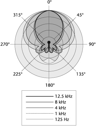
Figure 6-8. Polar pattern indicating differences in directionality at certain frequencies. Notice that the lower the frequency, the less directional the pickup.
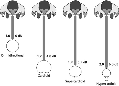
Figure 6-9. Differences in relative working distances among omnidirectional, cardioid, supercardioid, and hypercardioid microphones and their relative effectiveness in rejecting reverberation.
Although reach is the term commonly used to describe a mic’s relative working distance, it is misleading. A microphone does not reach out to pick up sound. A cardioid mic, for example, appears to have a farther reach than an omnidirectional mic. The difference in their pickup, however, is that the omnidirectional mic hears sound from all directions, whereas the cardioid mic hears sound approaching mainly from the front, rejecting sound in different degrees from the sides and the rear. This creates the perception that the cardioid mic enhances sound waves from the front.
A word of caution about polar patterns: Don’t believe everything you read. Looking good on paper is not enough. The microphone has to be put to the test in use to determine its actual response, particularly off-axis.
Clearly, a microphone’s operating principle (transducer) and directional characteristics affect the way it sounds. Other sonic features, which are contained in a specification sheet, should also be considered. The specifications are either generalized—giving the response details of a particular line of models for potential buyers—or they are specific to, and included with, the actual mic when it is purchased.
Microphone specifications are useful because they can shortcut the selection process. With the hundreds of professional microphones available, it is difficult to try more than a few of them at any one time. If you are looking for a mic with a particular polar pattern, frequency response, overload limit, and so on, reading a spec sheet can eliminate those mics that do not meet your need. A word of caution, however. Even when a spec sheet suggests that you may have found the “right” mic, regardless of how detailed the specifications are, there is only one ultimate test before selection: listening and doing what your ears tell you.
In addition to its type (transducer element) and directional characteristic(s), a microphone’s spec sheet includes the following sonic features: frequency response, overload limit, maximum sound-pressure level, sensitivity, self-noise, and signal-to-noise ratio. Proximity effect and humbucking are also considerations when selecting a mic.
A microphone’s frequency response is the range of frequencies that it reproduces at an equal level, within a margin of ±3 dB. That is, at a given level, a frequency will not be more or less than 3 dB off.
A microphone’s frequency response curve is displayed as a graph with the vertical line indicating amplitude (dB) and the horizontal line indicating frequency (Hz) (see Figure 6-10). It shows the tonal balance of the microphone pickup at a designated distance from a sound source, usually 2 or 3 feet.
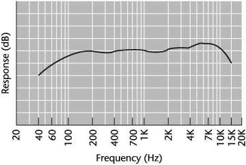
When the curve is reasonably straight or flat, response has little coloration—all frequencies are reproduced at relatively the same level. But flat is not necessarily desirable. In looking at a response curve, it is important to know for what purpose the microphone was developed and what your sonic requirements are. In Figure 6-12, for example, the bass begins rolling off at 150 Hz, there is a boost in the high frequencies between 4,000 and 10,000 Hz, and the high end rolls off beyond 10,000 Hz. Obviously, this particular mic would be unsuitable for instruments such as the bass drum, organ, and cello because it is not very sensitive to the lower frequencies from these instruments. It is also unsuitable for high-frequency sound sources, such as the female singing voice, cymbals, and the piccolo, because it is not that sensitive to their higher frequencies or harmonics. The mic was not designed for these purposes, however; it was designed for the speaking voice, and it is excellent for this purpose. Reproduction of frequencies through the critical upper bass and midrange is flat, the slight boost in the upper midrange adds presence, and the roll-offs in the bass and the treble are beyond the ranges of most speaking voices.
All microphones will distort if sound levels are too high—a condition known as overload—but some mics handle it better than others. Moving-coil and capacitor microphones are not as vulnerable to distortion caused by excessive loudness as ribbon mics. Moving-coil mics can take high levels of loudness without internal damage. Using a ribbon mic when there may be overload risks damaging the element, particularly with older models.
In the capacitor system, although loud sound-pressure levels may not create distortion at the diaphragm, the output signal may be great enough to overload the electronics in the mic. To prevent this, many capacitors contain a built-in pad. Switching the pad into the mic system eliminates overload distortion of the mic’s preamp, thereby reducing the output signal so many decibels (see Figure 6-21).
Maximum sound-pressure level is the level at which a microphone’s signal begins to distort. If a microphone has a maximum sound-pressure level of 120 dB-SPL, it means the mic will audibly distort when the level of a sound source reaches 120 dB-SPL. A maximum sound-pressure level of 120 dB is good, 135 dB is very good, and 150 dB is excellent.
In a microphone, distortion is measured as total harmonic distortion (THD). THD is a specification that compares the output signal with the input signal and measures the level differences in harmonic frequencies between the two. THD is measured as a percentage. The lower percentage, the better.
Sensitivity measures the voltage that a microphone produces (dBV) at a certain sound-pressure level. It indicates how loud a microphone is. Capacitor mics are loudest; ribbon mics are quietest. Sensitivity does not affect a mic’s sound quality, but it can affect the overall sound quality of a recording. A microphone with high sensitivity has a high voltage output and will not require as much gain as a mic with low sensitivity. Ribbon and small moving-coil mics have low sensitivity (–85 dBV), larger moving-coil mics have medium sensitivity (–75 dBV), and capacitor mics have high sensitivity (–65 dBV).
Self-noise, also known as equivalent noise level, indicates the sound-pressure level that will create the same voltage as the inherent electrical noise, or hiss, that a microphone (or any electronic device) produces. Self-noise is measured in dB-SPL, A-weighted. A fair self-noise rating is around 40 dB-SPL(A), a good rating is around 30 dB-SPL(A), and an excellent rating is 20 dB-SPL(A) or less.
Signal-to-noise ratio (S/N) is the ratio of a signal power to the noise power corrupting the signal and is measured in decibels. In relation to microphones, S/N is the difference between sound-pressure level and self-noise. For example, if the microphone’s maximum sound-pressure level is 94 dB and the self-noise is 30 dB-SPL, the signal-to-noise ratio is 64 dB. The higher the S/N, the less obtrusive the noise. An S/N of 64 dB is fair, 74 dB is good, and 84 dB and higher is excellent.
When any microphone is placed close to a sound source, bass frequencies increase in level relative to midrange and treble frequencies. This response is known as proximity effect or bass tip-up (see Figure 6-11).
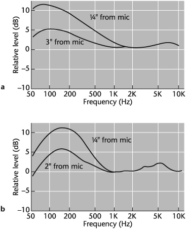
Figure 6-11. Proximity effect. (a) A typical cardioid moving-coil mic and (b) a cardioid capacitor mic.
Proximity effect is most pronounced in pressure-gradient (ribbon) microphones—mics in which both sides of the diaphragm are exposed to incident sound. Response is generated by the pressure differential, or gradient, between the sound that reaches the front of the diaphragm relative to the sound that reaches the rear. As mic-to-source distance decreases, acoustic pressure on the diaphragm increases. Because pressure is greater at lower frequencies and the path between the front and the rear of the diaphragm is short, bass response rises.
Response of directional microphones is, in part, pressure-gradient and therefore susceptible to proximity effect but not to the extent of ribbon mics. Omnidirectional microphones are not subject to proximity effect unless the mic is close enough to the sound source to be almost touching it.
Proximity effect can be a blessing or a curse, depending on the situation. For example, in close-miking a bass drum, cello, or thin-sounding voice, proximity effect can add power or solidity to the sound source. Where a singer with a deep bass voice works close to the mic, proximity effect can increase boominess, masking middle and high frequencies.
To neutralize unwanted proximity effect (rumble, or 60-cycle hum), most microphones susceptible to the effect include the feature, called bass roll-off, of a limited in-mic equalizer (see Figure 6-21). When turned on, the roll-off attenuates bass frequencies several decibels from a certain point and below, depending on the microphone, thereby canceling or reducing any proximity effect (see Figure 6-12).
Because bass roll-off has so many advantages, it has become a common feature even on mics that have little or no proximity effect. In some models, bass roll-off has been extended to include several different frequency settings at which attenuation can occur, or different levels of attenuation at the same roll-off frequency.
Another way to reduce proximity effect is to use a multiple-entry-port directional microphone because these mics have some distance between the rear-entry low-frequency ports and the sound source. At close mic-to-source distances, however, most multiple-entry-port microphones have some proximity effect.
To avoid proximity effect at close working distances down to a few inches, directional mics have been designed that are frequency independent. One such mic uses two transducers—one to process high frequencies, the other to process low ones. This two-way system design also produces a more linear response at the sides of the microphone.
Hum is an ever-present concern in audio in general and in microphone pickup in particular. In a microphone, hum is typically produced by stray alternating current (AC) magnetic fields at 50 or 60 Hz and is particularly a problem in dynamic mics. One way to minimize hum is to use balanced mic cables and connectors (see “Cables” and “Connectors” later in this chapter). Twisted-pair mic cables with good shield coverage are recommended; the braided shield is particularly effective. Because dynamic microphones are especially susceptible to hum, use one with a humbuck coil.
Humbucking is not so much a response characteristic as it is a feature built into many moving-coil microphones. It is designed to cancel the effect of induced hum by introducing a 50/60 Hz component equal in level and opposite in polarity to the offending hum. Because the original and the introduced hums are opposite in polarity, they cancel each other. Humbucking is affected with a humbuck coil that is built into the microphone system and requires no special operation to activate it. The effectiveness of the hum reduction varies with the microphone.
Certain mics have been designed to meet particular production needs because of their size, pickup characteristics, sound, appearance, or a combination of these features. A number of different types of mics can be considered as special-purpose: lavaliere (minimic), shotgun, parabolic, headset and earset, contact, boundary, noise-canceling, USB, multidirectional, system, stereo, middle-side, infinitely variable pattern, binaural and surround, high definition, and digital.
The lavaliere microphone was originally hung around the neck, hence the name (lavaliere is French for “pendant”). Today, these mics are usually attached to a tie, to the front of a dress in the sternum area or at the neckline, or to a lapel. They are quite small and are known as miniature microphones, or mini-mics (see Figure 6-13). When they have to be concealed, they are placed in the seam or under clothing, behind the ear, or in the hair.
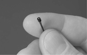
Figure 6-13. Lavaliere miniature microphone. This model measures 1/10 inch in diameter. It features three protective caps that both keep moisture out and alter the mic’s color and frequency response to match desired applications. Frequency responses using the three protective caps are flat, +0 dB; bright, +4 dB; and very bright, +8 dB.
Mini-mics designed for use under the chin have two things in common: Most are omnidirectional, although directional minis may be used when background noise is especially loud, and many have a built-in high-frequency boost. The omnidirectional pickup is necessary because, with the mic mounted away from the front of the mouth, a speaker does not talk directly into it but across it. A directional response would not pick up much room presence and would sound too dead. In addition, as a speaker talks, high frequencies, which are directional, travel straight ahead. The chin cuts off many of the less directional high frequencies with longer wavelengths that otherwise would reach the mic. The built-in high-frequency boost compensates for this loss. If you hold in front of your mouth a mini-mic designed for use under the chin, its response will be overly bright and hissy. Their sensitivity to breathing and popping sounds also makes minimics unsuitable for use in front of the mouth; they have no pop filter, although windscreens come with many models (see “Windscreens and Pop Filters” later in this chapter).
The mini-mics in common use are electret capacitors. Generally, they fall into two groups: the proximity oriented mini mic, which adds presence to close speech while reducing background sound, and the transparent mini mic, which picks up more ambience, thereby blending more naturally with the overall sound.
The shotgun microphone is so-called because it resembles a rifle barrel (see Figure 6-38, microphone, far right). The basic principle of the shotgun microphone is that it attenuates sound from all directions except a narrow angle at the front. This creates the perception that it has greater reach. Compared with an omnidirectional microphone, mic-to-source pickup can be 1.7 times greater with a cardioid, 1.9 times greater with a supercardioid, and 2 times greater with a hypercardioid and not affect on-mic presence (see Figure 6-9). Some shotguns are better than others, so be careful when choosing one, especially for use in mediocre acoustic environments. The main consideration should be how well it discriminates sound, front-to-back, in a given situation.
The comparison can be made between a shotgun mic and a telephoto lens on a camera. A telephoto lens compresses front-to-back space. Shot with such a lens, an auditorium, for example, would appear smaller, with the rows of seats closer together than they really are. A shotgun mic does the same thing with acoustic space: It brings the background and the foreground sounds closer together. The extent of this spatial compression depends on the mic’s pickup pattern. Of the three types of shotgun pickups—super-, hyper-, and ultracardioid—the supercardioid compresses front-to-rear sound the least and the ultracardioid compresses it the most.
Shotgun mics can sacrifice quality for a more focused pickup. One reason why is because shotguns are usually used for speech, and the frequency ranges of the male and female speaking voices are not very wide. Another reason is that the shotgun becomes less directional at lower frequencies, as do all directional mics, due to its inability to deal well with wavelengths longer than the length of its tube, called the interference tube. Interference tubes come in various lengths from 6 inches to 3 feet and longer. The longer the interference tube, the more highly directional the microphone. If the tube of a shotgun mic is 3 feet long, it will maintain directionality for frequencies of 300 Hz and higher—that is, wavelengths of approximately 3 feet and less. For 300 Hz and lower, the mic becomes less and less directional, canceling fewer and fewer of the lower frequencies. Many shotgun mics do have bass roll-off, however.
Most shotgun microphones have monaural pickup. Models with stereo pickup are also available.
Another microphone used for long-distance pickup, mainly outdoors at sporting events, film and video shoots, in gathering naturalistic recordings of sounds in the wild, and for surveillance is the parabolic microphone system. It consists of either an omni- or a unidirectional mic facing inward and attached to a parabolic reflector. Fine-tuning the pickup is done by moving forward or backward the device that holds the mic. Some parabolic systems enable electronic magnifying of faint or distant sounds by several decibels. Parabolic systems are also available with a built-in recorder.
More than canceling unwanted sound, the parabolic dish, which is concave, concentrates the sound waves from the sound source and directs them to the microphone (see Figure 6-14). As with the shotgun mic, the parabolic mic is most effective within the middle-and high-frequency ranges; its sound quality is not suitable for critical recording.
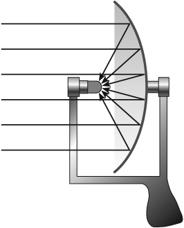
Figure 6-14. Parabolic microphone system. The system uses a concave dish that concentrates the incoming sound waves, based on the principle that a sound wave’s angle of incidence is equal to its angle of reflectance (see Chapter 4). The attached microphone can be wired or wireless. With wireless mics the transmitter is usually attached to the parabolic reflector (see “Wireless Microphone System” later in the chapter).
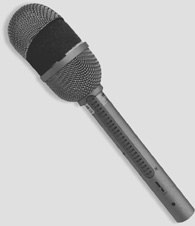
The headset microphone is a mic mounted to headphones. The headphones can carry two separate signals: The program feeds through one headphone and the director’s feed through the other. The microphone is usually a moving-coil type with a built-in pop filter because of its ability to handle loud sound-pressure levels that sports announcers, in particular, project. It may be omnidirectional for added event ambience or cardioid to keep background sound to a minimum. Hypercardioid models are designed for high rejection of unwanted sounds.
The headset system frees the announcer’s hands and frontal working space. Another benefit is that the announcer’s distance from the mic does not change once the headset is in place. Small and lightweight headset mics are also available. They are particular popular with singers doing TV, live concerts, and for dance-oriented performances (see Figure 6-15).
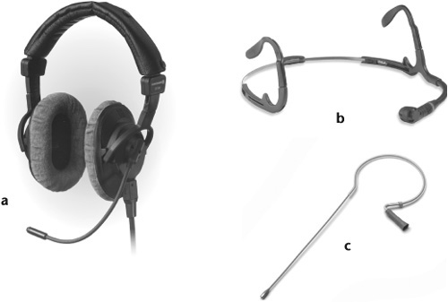
Figure 6-15. Headset microphone systems. (a) Headset microphone system with omnidirectional mic. (b) Small headset microphone system with cardioid mic for vocalists, singing instrumentalists, and radio talk-show hosts. (c) Headset mic with a flexible, telescoping band that fits snugly around the back of the head and is easily concealed under the hair. It has a telescoping boom that can be bent for a custom fit. Headset microphone systems can be wired or wireless.
The earset microphone has no headband. It consists only of an earpiece cable-connected to a microphone, usually omni- or unidirectional. If keeping a mic unobtrusive is important, the earset microphone is far less apparent on-camera than headset models (see Figure 6-16).
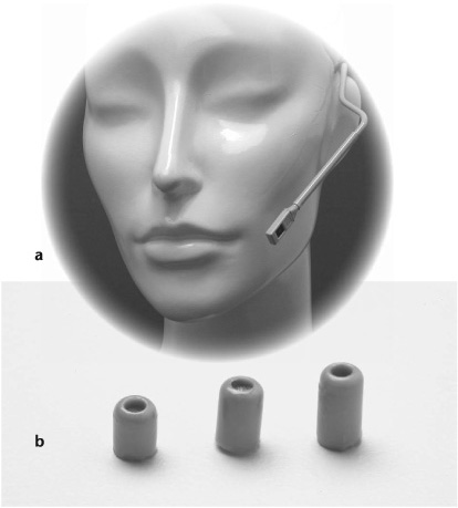
Figure 6-16. Earset microphone. (a) This model comes with protective caps (b) to keep perspiration, makeup, and other foreign materials out of the microphone. The caps also provide different high-frequency responses to control the amount of presence or crispness in the sound. Earset mics can be wired or wireless.
Not to quibble about semantics, but some lavalieres, particularly the miniature models, can be classified as contact microphones—and vice versa. Essentially, the difference between the two is that a contact mic, also called an acoustic pickup mic, has been specially designed to attach to a vibrating surface (see Figure 6-17). Instead of picking up airborne sound waves as conventional mics do, it picks up vibrations through solid materials.
When a conventional microphone is placed on or near a surface, such as a wall, floor, or ceiling, sound waves reach the mic from two directions—directly from the sound source and reflected from the nearby surface. The reflected sound takes longer to reach the microphone than the direct sound because it travels a longer path. This time difference causes phase cancellations at various frequencies, creating a comb-filter effect, which gives sound an unnatural, hollow coloration (see Figure 6-18). The boundary microphone positions a mini-capacitor mic capsule very close to, but at an optimal distance from, a sound-reflecting plate—the boundary. At this optimal distance, direct and reflected sound travel the same distance and reach the mic at about the same time, thereby eliminating phase cancellations. Any comb filtering occurs out of the range of human hearing.
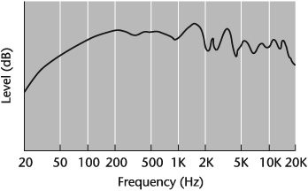
Figure 6-18. Comb-filter effect. Delayed reflected sound combined with direct sound can create this effect.
Boundary microphones have an electret transducer. Their pickup pattern is half omnidirectional or hemispheric, half cardioid, half supercardioid, or stereophonic. Their response is open and, in suitable acoustics, spacious (see Figure 6-19).
As stated earlier, a shotgun mic is designed to pick up at a distance and in so doing focuses sound by reducing unwanted background noise, so long as it is correctly aimed and does not pull in unwanted ambience from behind the primary sound source. The noise-canceling microphone is also intended to reject unwanted ambient sound, but it is designed for use close to the mouth. Because of its particular electronics, the noise-canceling mic must be used close to the sound source. If it is held even a short distance away, the performer’s sound may be clipped, and the pickup may be off-mic entirely.
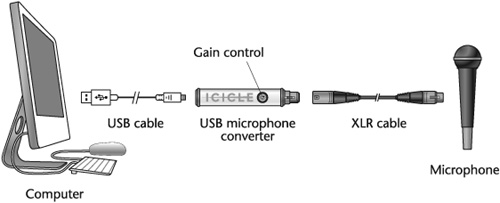
The USB microphone was developed for those who want to record directly into a computer without an audio interface, such as a console, control surface, or mixer. (USB stands for Universal Serial Bus, a protocol used worldwide for data transfer between peripheral devices and computers.)
Like all microphones classified as digital, USB mics have a built-in analog-to-digital (A/D) converter (see “Digital Microphones” later in this chapter). They are available in both moving-coil and capacitor models. With capacitor USB mics, it is important to make sure that, because they use phantom power (which can generate noise) and because USB power can be noisy in the first place, the mic has compensating power conditioning and noise filtering to ensure sound quality that can run from decent to excellent. Another possible source of noise is the quality, or lack thereof, of the A/D converter.
Frequency response among USB mics varies from as narrow as 40 Hz to 14 kHz to as wide as 20 Hz to 20 kHz. Bit depth is generally 16-bit or 18-bit, with sampling rates that range from 8 to 48 kHz (see Chapter 9). Features such as a pad, an internal shock mount, bass roll-off, and variable pickup patterns vary with the mic. It is wise to keep in mind that regardless of how good the USB microphone may be, if problems occur with sound quality, the cause may the programs used or the applications to which the USB mic is connected. One such problem may be latency—the period of time it takes data to get from one designated point to another (see Chapter 10).
Development of the USB microphone converter (or adapter) makes it possible to connect any dynamic or capacitor XLR mic into a computer via USB (see “Connectors” later in this chapter). Depending on the model, a converter may include a microphone preamp, phantom power, headphone monitoring, and level controls for microphone balancing and playback (see Figure 6-20).
Microphones with a single directional response have one fixed diaphragm, or ribbon. By using more than one diaphragm and a switch to select or proportion between them, or by including more than one microphone capsule in a single housing, a mic can be made multidirectional, or polydirectional, providing two or more ways to pick up sound from various directions (see Figure 6-21).
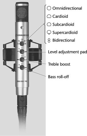
Figure 6-21. Multidirectional microphone with five pickup patterns: omnidirectional, subcardioid, cardioid, supercardioid, and bidirectional. This microphone also has a three position level adjustment pad (0, –6 dB, and –12 dB; second control from the top), a three-position treble boost at 10 kHz (0, +3 dB, and +6 dB; third control from top), and a bass roll-off at 50 Hz (–3 dB and –6 dB; bottom control). See “Overload Limit” and “Proximity Effect” earlier in this chapter.
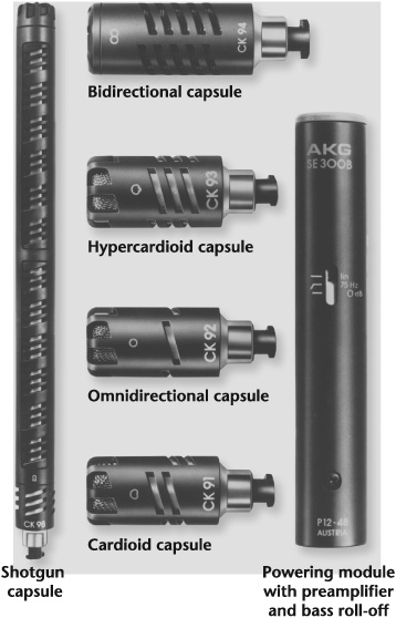
One multidirectional mic of sorts is the system microphone, which uses interchangeable heads or capsules—each with a particular pickup pattern—that can be mounted onto a common base (see Figure 6-22). Because these systems are capacitors, the power supply and the preamplifier are in the base, and the mic capsule simply screws into the base. Any number of directional capsules—omnidirectional and bidirectional, cardioid, super-cardioid, and hypercardioid—can be interchanged on a single base. Some system mic models may only include two or three directional capsules.
Stereophonic microphones are actually microphone capsules with electronically separate systems housed in a single casing. The stereo mic has two distinct elements which, in some models, can be remote-controlled. Generally, stereo mics are configured in one of three ways: The lower and upper elements are stationary (see Figure 6-23); one element is stationary and the other element rotates 180 to 360 degrees to facilitate several different stereo pickup patterns, depending on the pickup design (see Figure 6-24); both elements rotate (see Figure 6-25).
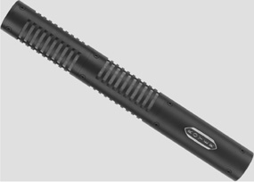
Figure 6-23. A stereo pair of matched ribbon mics mounted one above the other in a single casing. The two ribbons’ pickup patterns are 90 degrees off-axis from each other.

Most middle-side (M-S) microphones consist of two mic capsules housed in a single casing. One capsule is designated as the midposition microphone aimed at the sound source to pick up mostly direct sound; it is usually cardioid. The other capsule is designated as the side-position microphone; it is usually bidirectional with each lobe oriented 90 degrees laterally to the sides of the sound source to pick up mostly ambient sound. The outputs of the cardioid and bidirectional capsules are combined into a sum-and-difference matrix through a controller that may be external or internal (see Figure 6-26).
Figure 6-26. Combined middle-side and stereo microphone. In the stereo mode, this microphone uses its internal matrix to mix the middle and side signals. In the L (low) position, the stereo image spread is small. In the M (medium) position, it is wider. The H (high) position provides the widest stereo spread. In the M-S output mode, the internal stereo matrix is bypassed. The pickup from the front-facing mic capsule is cardioid, and from the side-facing capsule it is bidirectional.
Instead of having selectable pickup patterns, the infinitely variable pattern microphone allows fine adjustments to any position from omnidirectional through bi- and unidirectional patterns. These microphones typically also include variable controls for bass roll-off and pad.
Binaural microphony picks up sound in three, instead of two, dimensions. The addition of vertical, or height, information to the sonic depth and breadth reproduced by conventional stereo and M-S mics makes sound quite spacious and localization very realistic.
Generally, binaural microphone systems consist of an artificial head with a pair of pinnae ear replicas and a matched pair of omnidirectional capacitor microphones or microphone capsules placed in the ear canals. Some go so far as to construct the head and the upper torso based on statistical averaging and variations in real humans. Some even feature felt hair and shoulder padding to simulate the characteristics of hair and clothing.
Surround sound adds greater front-to-rear depth and side-to-side breadth (assuming side placement of the loudspeakers) than stereo but not quite the vertical imaging or sonic envelopment of binaural sound.
Surround-sound microphone systems usually house separate microphones, or microphone capsules, for each pickup in a given surround-sound format and include a controller to adjust spatial imaging. For example, for the 5.1 format there are six microphones for left center, center, right center, left and right surrounds, and low frequency pickup (see Figure 5-15 and Chapter 13). In the 7.1 format, eight separate microphones are delegated for left center, center, right center, left and right side surrounds, left and right rear surrounds, and low-frequency pickup. The arrangement of the microphone elements varies from system to system, however, and a few systems employ fewer mics in a quasi-binaural/surround configuration to reproduce the surround-sound imaging.
The term high definition microphone is a trademark of Earthworks, Inc., and refers to its line of these types of mics and its proprietary technology. But so-called high definition microphones, regardless of manufacturer, are generally very high-quality instruments with superior transient response; shorter diaphragm settling time after vibration; extended frequency response; fewer electronic features to reduce signal path; low distortion at high sound-pressure levels; and improved stabilization of the polar response.
The mediocre to poor sound quality in laptop computers has long been a bane to users. Upgraded loudspeakers have not helped that much because of the poor quality of available microphones. This problem has been alleviated with the development of a high definition digital microphone for laptop computers and other broadband devices.
One such microphone has wideband frequency response and complies with the audio performance requirement for wideband transmission in applications such as Voice-over-Internet Protocol (VoIP) delivering high definition voice quality; is surface-mountable; and provides a L/R user-select function that allows a single device to be configured as either a left or a right microphone.
When conventional mics are used in digital recording, the analog signal is converted to a digital signal at some point in the sound chain—but after it leaves the microphone. With the digital microphone, the analog signal is converted to digital at the mic capsule, which means the signal going through the sound chain is digital immediately after it is transduced from acoustic energy into electric energy.
A microphone modeler is not an actual microphone but a microphone simulator that can be added to a hard-disk recording system as a plug-in (see Figure 6-27). It is designed to emulate the sounds of most professional-grade microphones.
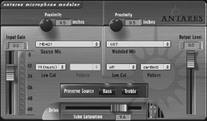
Say you have a track recorded with a Sennheiser MD421 and you want to make it sound as though it had been recorded with a Neumann U-87. The mic modeler removes from the audio the characteristics of the original microphone and applies those of the target mic. The microphone modeler can be used either after a track has been recorded or during recording to shape the desired sound. Although the process is not completely accurate in reproducing a particular mic’s sound, it does create good virtual similarities of a given microphone’s identifying characteristics, thereby providing a much larger mic collection than a recordist might have.
It is useful to note, however, that a microphone modeler cannot make a $30 dynamic mic sound like a $3,000 tube-type capacitor; and because many factors affect a recording, such as a studio’s acoustics, the microphone preamplifier, and mic-to-source distance, it cannot make poorly recorded material sound good.
The wireless microphone system, also called a cordless mic, an FM mic, a radio mic, and a transmitter mic, consists of three main components (four, if you count the mic): transmitter, antenna, and receiver (see Figure 6-28). Additional system components may include cables and distribution systems. A standard mic is used with the system in one of four ways: lavaliere, handheld, headset, and boom. The lavaliere system typically uses a mini-mic connected to a battery-powered bodypack transmitter, which may be wired or wireless. The handheld wireless mic operates with the transmitter and the microphone in a single housing (see Figure 6-29). The headset and earset mics use the bodypack transmitter. The boom microphone’s transmitter is usually a plug-on (see Figure 6-30). The plug-on is a wireless transmitter with an XLR connector (discussed later in this chapter) that plugs into the end of the mic.
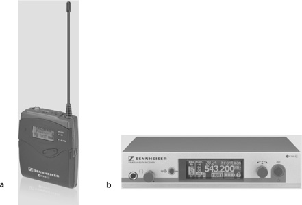
Figure 6-28. Wireless microphone system. (a) Pocket transmitter. Features include: multiple UHF frequency selection; long-range transmission; illuminated graphic display; auto-lock to avoid accidental change of the selected frequency; mute function; and wireless synchronization of transmitters via infrared interface from the receiver. (b) Receiver. Features include: diversity reception (see “Diversity Reception” later in this section); illuminated graphic display also showing transmitter settings; automatic frequency scan to search for available frequencies; Ethernet port; and integrated equalizer and soundcheck mode.
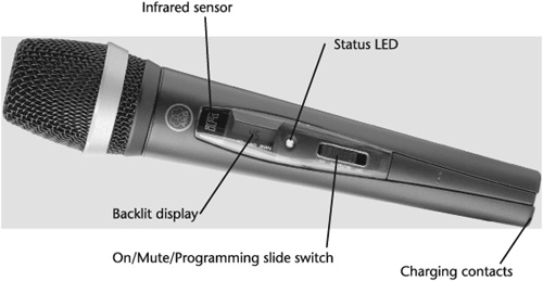
The microphone’s signal is sent to the transmitter, which converts it to a radio signal and relays the signal to a receiver anywhere from several feet to many yards away, depending on the system’s power. The receiver converts the radio signal back into an audio signal. The transmitter usually includes a flexible wire antenna and controls for on/off power, frequency selection, microphone loudness, and microphone mute. Status lights indicate when the mic is on or off, the battery is low, and the signal is overloading.
The receiver usually includes the antenna(s) and controls for frequency selection (the frequency must match that of the transmitter); the signal level; the squelch-mute threshold control so the receiver picks up the desired signal and mutes when the signal is turned off; and indicator status lights to indicate the level of the incoming signal, the level of the audio sent from the receiver down the signal chain, mute, and diversity operation (see “Diversity Reception” later in this chapter).
Before using a wireless microphone system, consider a few operational and performance criteria: frequency assignment and usage, diversity reception, audio circuitry, sound quality, transmission range, antenna, and power supply.
Frequency assignment and usage—. Wireless microphone systems transmit on frequencies in the very high frequency (VHF) and ultra high frequency (UHF) bands. The VHF ranges are: low band—49 to 108 megahertz (MHz); and high band—174 to 216 MHz. The UHF ranges are: low band—470 to 698 MHz; and high band—900 to 952 MHz. The 700 MHz band that was also used for wireless microphone usage was reassigned in 2009 for new commercial services and public safety usage. Most wireless microphone manufacturers anticipating the reallocation by the Federal Communications Commission (FCC) no longer produce wireless systems that transmit in the 700 MHz band.
The differences between VHF and UHF wireless mic systems relate to bandwidth, flexibility, power, multipath reception, and cost. Because the VHF bandwidth is far narrower than UHF, there is much less room for available frequencies (see Figure 6-31). This limits both its use in large metropolitan areas, where the spectrum is crowded with VHF TV and FM radio stations, and its flexibility in operating a number of wireless systems simultaneously. Therefore, using low-band VHF wireless systems is not recommended because the band is prone to interference from many users. Also, transmitter power is limited, and the required antenna size limits portability.
Multipath—. Wireless systems in the higher frequencies, and therefore transmitting shorter wavelengths, are vulnerable to instances of multipath reception. Multipath is a physical phenomenon in which more than one radio frequency (RF) signal from the same source arrives at the receiver’s front end, creating phase mismatching (see Figure 6-32).
Fixed- and Variable-Frequency Systems—. Wireless microphones operate on either a fixed frequency or a variable frequency system. Fixed-frequency wireless microphone systems, which are less expensive than variable systems, are useful in situations where the mic does not change locations or there are relatively few FM and TV stations in the area or both. These factors make it relatively easy to find an available operating frequency and the wireless system to match it. In large cities, or if the mic is used in different locations, the variable-frequency wireless microphone system is necessary. Also known as frequency-agile systems, some of these use a technology that automatically selects the best channels at any given time for seamless microphone performance.
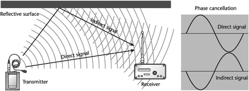
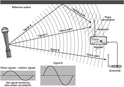
Diversity reception—. A wireless microphone system transmits radio waves from a transmitter, through the air, to a receiver. Because the waves are transmitted line-of-sight, there is the danger that the radio waves will encounter obstructions en route to the receiver. Another potential hindrance to signal reception could result if the transmitter is out of range. The problem with multipath reception may be a third difficulty. Any of these problems creates a dropout or null in the transmission. Dropout is a momentary loss of the signal at the receiver. The technique used to deal with dropout is known as diversity reception. Basically, diversity reception ensures that the receiver can satisfactorily process an impeded signal from the transmitter (see Figure 6-33).
To check if a wireless system is operating correctly, walk the signal path from the transmitter to the receiver, speaking into the microphone as you go. If you hear dropout, buzzing, or any other sonic anomaly, note the location(s). First check the system to make sure it is in proper working order. If it is, change microphone placement or receiver location, if you can, and retest the signal transmission.
Audio circuitry—. The nature of radio transmission inhibits the quality of the audio signal. To counteract this, the audio signal is processed in two ways, through equalization and companding.
Equalization, in this instance, involves a pre-emphasis and a de-emphasis of the signal to minimize the level of hiss (high-frequency noise) that is unavoidably added during transmission. Pre-emphasis boosts the high frequencies in transmission; de-emphasis reduces the high-frequency noise at the receiver. The equal but opposite process reduces noise by up to 10 dB.
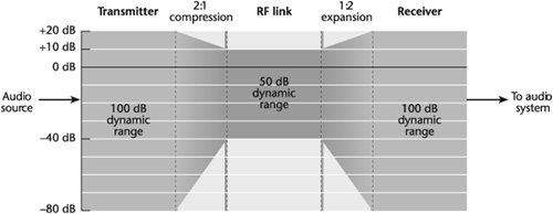
Companding, a contraction of the words compressing and expanding, compensates for the limited dynamic range of radio transmission. The input signal varies over a range of 80 dB and is compressed at the transmitter to a range of 40 dB, a factor of 2 to 1. At the receiver, the signal is expanded by 40 dB to its original dynamic range, a factor of 1 to 2. Even though companding sometimes creates noise, coloration, and the audible pumping sound caused by compander mistracking, particularly in less expensive systems, a wireless mic is always far better off with companding than without it (see Figure 6-34).
Another process important to signal reception at the receiver is called squelch. The function of this circuit is to silence or mute the receiver’s audio output when there is no radio signal. Otherwise, the “open” receiver could pick up background radio noise or another signal.
Sound quality—. Wireless microphone systems vary widely in quality. Clearly, in professional audio, only a system with wide frequency response and dynamic range should be used. Frequency response should be well beyond the frequency range of the sound recorded. Good wireless systems are now capable of dynamic ranges up to 115 dB. A system with poorer dynamic range needs more compression at the transmitter and more expansion at the receiver, creating an annoying squeezed sound that results from companding loud levels.
Transmission range—. The transmission range of wireless microphone systems varies from as short as 100 feet to as long as 2,500 feet. The range of a given system is provided in its specifications. Transmission range should be based on need. Obviously, a shorter range would suffice in a studio or theater whereas a longer range would be necessary in a stadium or in a long shot for a film.
Antenna—. The antenna should be fully extended and several feet away from any obstruction, including the floor. With transmitters, avoid taping “whip” antennas (and bodypacks) to the skin, as perspiration inhibits signal transmission. Both the transmitter and the receiver antennas should be oriented either vertically or horizontally. If they are not, it hinders reception. Because performers usually stand, the most common antenna position is vertical. Some antennas are more effective than others. To improve system performance, a dipole antenna could increase signal pickup by 3 dB or more.
Power supply—. Wireless mic systems use a variety of battery types, such as AA, 9 V, and VDC (voltage DC). Battery lifetime varies from a few hours to up to 10 hours. Alkaline batteries are good, but lithium batteries last longer. To reduce power supply problems, batteries should be replaced before they have a chance to run down. It is simply not worth holding up a production session to save a few cents, trying to squeeze maximum life out of a battery.
![New FCC frequency allocations after the digital television (DTV) transition. (TVBD is short for personal and portable TV band devices, previously referred to as white space devices [WSDs]).](http://imgdetail.ebookreading.net/design/7/9781435460553/9781435460553__working-with-audio__9781435460553__graphics__f0096-01.jpg)
Wireless microphones systems are available in analog and digital formats. By digitizing the signal, the audio gets converted to digital right away at the transmitter. It is then sent to the receiver where the data is received; checked for errors; corrected, if necessary; and converted back to analog. This process has several advantages over analog. Among them are a more robust signal; considerable reduction, if not elimination of interference and overall noise, in RF in the radio path; and the need for squelch.
Microphones come with various accessories. The most common are windscreens and pop filters, shock mounts, cables, connectors, and stands and special-purpose mounts.
Windscreens and pop filters are designed to deal with distortion that results from blowing sounds caused by breathing and wind, the sudden attack of transients, the hiss of sibilant consonants like s and ch, and the popping plosives of consonants like p and b. (In practice, the terms windscreen and pop filter are used interchangeably, but for clarity of discussion here they are given slightly different applications.)
Windscreens are mounted externally and reduce the distortion from blowing and popping but rarely eliminate it from particularly strong sounds (see Figure 6-35). A pop filter is built-in and is most effective against blowing sounds and popping (see Figure 6-36). It allows very close microphone placement to a sound source with little fear of this type of distortion.
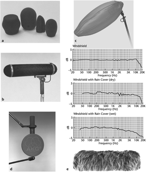
Figure 6-35. Windscreens. (a) Various windscreens for conventional microphones. (b) So-called zeppelin windscreen enclosure for shotgun microphone. (c) Lightweight collapsible windshield consisting of a light metal frame covered with a fine-mesh foam material. The windshield comes with a rain cover. The response curves illustrate the differences in response characteristics without the rain cover, with the rain cover dry, and with the rain cover wet. It should be noted that all windscreens affect frequency response in some way. (d) Stocking (fabric) windscreen designed for use between the sound source and the microphone. This particular model has two layers of mesh material attached to a lightweight wooden ring. (e) Windscreen cover, or windjammer, to cover zeppelin-type windscreens.
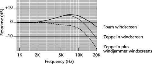
Windscreens also slightly affect response, somewhat reducing the crispness of high frequencies (see Figure 6-37). Many directional microphones with pop filters are designed with a high-frequency boost to compensate for reduced treble response.
Pop filters, also known as blast filters, are mainly found in moving-coil, newer ribbon, and some capacitor microphones, particularly directional models, because they are more susceptible than omnidirectional mics to breath and popping noise due to their partial pressure-gradient response. They are also more likely to be used closer to a sound source than other microphone types. An omnidirectional mic is about 15 dB less sensitive to wind noise and popping than a unidirectional mic of similar size.
Another way to minimize distortion from sibilance, transients, blowing sounds, and popping is through microphone placement (see Chapter 7).
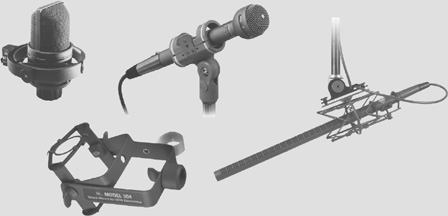
Because solid objects are excellent sound conductors, the danger always exists that unwanted vibrations will travel through the mic stand to the microphone. To reduce noises induced by vibrations, place the microphone in a shock mount—a device that suspends and mechanically isolates the mic from the stand (see Figure 6-38). Some microphones are designed with a built-in shock absorber.
A microphone cable is either a balanced line—consisting of two conductors and a shield—or an unbalanced line—consisting of one conductor with the shield serving as the second conductor. A quad mic cable uses a four-conductor design for added noise control. As with all professional equipment, the balanced line is preferred because it is less susceptible to electrical noise.
When winding mic cable, do not coil it around your arm, and be careful not to make the angle of the wrap too severe or it can damage the internal wires. It is also a good idea to secure the cable with a clasp specially made for this purpose to prevent it from getting tangled (see Figure 6-39).
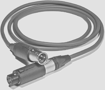
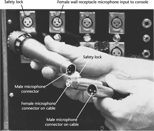
Most professional mics and mic cables use a three-pin plug that terminates the two conductors and the shield of the balanced line. These plugs are generally called XLR connectors (X is the ground or shield, L is the lead wire, and R is the return wire). Usually, the female plug on the microphone cable connects to the mic, and the three-prong male plug connects to the console (see Figure 6-40). It is always important to make sure the three pins in all microphones used in a session are connected in exactly the same way. If pin 1 is ground, pin 2 is positive, and pin 3 is negative, all mics must be wired in the same configuration; otherwise, the mismatched microphones will be electrically out of polarity and reduce or null the audio level.
Just as there are many types of microphones to meet a variety of needs, numerous microphone mounts are available for just about every possible application. Commonly used microphone mounts are shown in Figures 6-41 to 6-49.
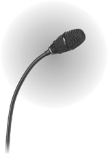
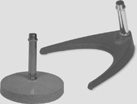
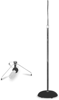
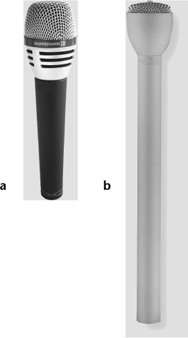
Figure 6-46. Handheld microphones. (a) Microphone with thin tube. It is easily handheld, is shock resistant, and has a pop filter. All are essential in a handheld microphone. (b) Handheld mic with a long handle for added control in broadcast applications and to provide room for a microphone flag.
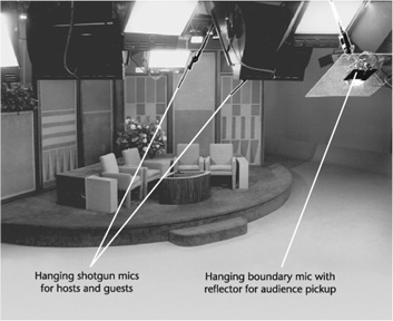
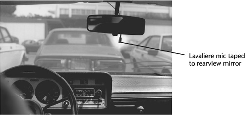
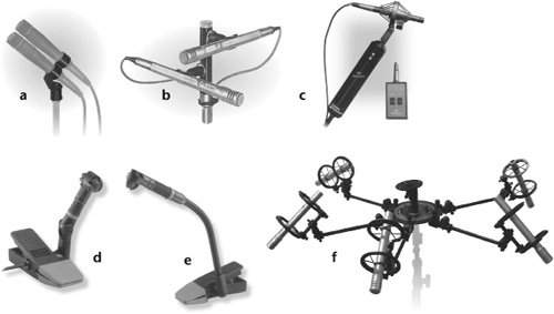
Figure 6-49. Special microphone mounts. (a) Redundant mono microphone mount. (b) Stereo microphone mount. (c) Remote panner boom mount and control module. (d) Hypercardioid microphone and mount for attachment to drums. (e) Hypercardioid microphone and mount for attachment to brass and woodwind instruments. (f) Mount for surround-sound miking.
Poor care of audio equipment adversely affects sound quality—this cannot be stressed enough. Moisture from high humidity or breath can greatly shorten a microphone’s life. When moisture is a problem, a windscreen will help protect the microphone element. Avoid blowing into a mic to check if it is on—in addition to the moisture problem, the force can drive particles through the grille and onto the diaphragm.
Ribbon mics are especially sensitive to the force of air pressure from blowing into the grille. Capacitor mics are also sensitive to air turbulence, not only from blowing but from fans and blowers. In fact, a breath blast can perforate a capacitor mic’s diaphragm. Be sure to turn off phantom power when a capacitor mic is not in use. The electric charge attracts dust to the mic’s diaphragm. While the phantom power is on, do not plug or unplug the mic cable; the abrupt power change could damage the mic’s preamp.
Dirt, jarring, cigarette smoke, oil from hands, and pop filters clogged with saliva and/or lipstick also reduce microphone efficiency. Microphones should be cleaned and serviced regularly and kept in carrying cases when not in use. Microphones left on stands between sessions should be covered with a cloth or plastic bag but not so tightly as to create a condensation problem. The working environment should be temperature- and humidity-controlled, kept clean, and vacuumed regularly.
Microphones are transducers that convert acoustic energy into electric energy. The device that does the transducing is called the element.
Impedance refers to resistance to the flow of voltage in a circuit. The lower the impedance, the better. Professional microphones (and equipment) are low impedance.
The elements in professional microphones operate on one of two physical principles: magnetic induction and variable capacitance.
The two types of professional mics that use magnetic induction are the moving-coil mics and the ribbon mics. The type of professional microphone using variable capacitance is the capacitor mic.
Capacitor microphones require a power supply to operate.
Each type of microphone is unique. One type is not much better than another as it is more suitable for a particular application.
Microphones pick up sound from essentially three directions: all around—omnidirectional; front and rear—bidirectional; and front only—unidirectional.
The unidirectional, or cardioid, design has even narrower pickup patterns. They are supercardioid, hypercardioid, and ultracardioid.
A microphone’s directional sensitivity can be displayed graphically in a polar response diagram.
A microphone’s unidirectionality is facilitated by ports at the side and/or rear of the mic that cancel sound coming from unwanted directions.
Directional sensitivity in a unidirectional microphone varies with frequency: The higher the frequency, the more directional the pickup; the lower the frequency, the less directional the pickup.
A microphone’s frequency response is the range of frequencies it produces at an equal level, within a margin of ±3 dB. Its frequency response curve can be displayed as a graph.
All microphones will distort if sound levels are too high—a condition known as overload.
Maximum sound-pressure level is the level at which a microphone’s output signal begins to distort.
To help protect against loudness distortion, many capacitor mics are equipped with a pad to reduce overloading the mic’s electronics.
Sensitivity measures the voltage a microphone produces (dBV) at a certain sound-pressure level. It indicates how loud a microphone is.
Self-noise, also known as equivalent noise level, indicates the sound-pressure level that will create the same voltage as the inherent electrical noise, or hiss, a microphone (or any electronic device) produces.
Signal-to-noise ratio (S/N) is the ratio of a signal power to the noise power corrupting the signal and is measured in decibels. In relation to microphones, S/N is the difference between sound-pressure level and self-noise.
Bidirectional and most directional microphones are susceptible to proximity effect, or bass tip-up—an increase in the level of bass frequencies relative to midrange and treble frequencies—when they are placed close to a sound source. To neutralize proximity effect, most of these microphones are equipped with bass roll-off.
Hum is an ever-present concern in microphone pickup. In a mic, it is typically produced by stray alternating current (AC) magnetic fields at 50 or 60 Hz and is particularly a problem in dynamic mics. There are several ways to minimize hum.
One method used to reduce hum is the humbuck coil built into some dynamic microphones.
Microphones have been developed for special purposes: for unobtrusiveness, the lavaliere and mini-mics; the shotgun and parabolic mics for long-distance pickup; the headset and earset mics to keep background sound to a minimum by maintaining a close mic-to-source distance; the contact mic for use on a vibrating surface; the boundary mic for use on a boundary (a hard, reflective surface) so that all sound pickup at the microphone is in phase; the noise-canceling mic for use close to the mouth with excellent rejection of ambient sound; the USB mic to record directly to a computer without an audio interface; multidirectional and system microphones, which have more than one pickup pattern; stereophonic, middle-side (M-S), and infinitely variable pattern microphones; the binaural mic for three-dimensional sound imaging; the surround-sound mics for surround-sound pickup; the high-definition mic for extremely high-quality reproduction; and the digital mic, which converts the analog signal to digital when the acoustic energy is transduced to electric energy.
A microphone modeler is not an actual microphone but a microphone simulator that can be added to a hard-disk recording system as a plug-in. It is designed to emulate the sounds of most professional-grade microphones.
When using a wireless microphone system, consider the following operational and performance criteria: frequency assignment and usage, diversity reception, audio circuitry, sound quality, transmission range, antenna, and power supply.
Windscreens and pop filters are used to reduce distortion caused by wind and transients. An external shock mount, or a built-in shock absorber, is used to prevent unwanted vibrations from reaching the microphone element.
Standard accessories used for professional microphones include the following: twin conductor cables called balanced lines, XLR connectors, and various types of stands and clips for microphone mounting.
Proper care is very important to the functioning and the sound quality of a microphone.