
Little in production and postproduction can be accomplished without synchronization—the ability to lock two or more signals or devices that have microprocessor intelligence so that they operate at precisely the same rate. That includes almost any combination of audio, video, and film equipment, from a simple audio-to-audio or audio-to-video recorder interface—analog or digital, tape or disk—to a complete studio system that interfaces a digital audio workstation, console, synthesizer, effects processor, and other equipment throughout a facility.
Accurate synchronization requires a system to code and coordinate the recording media and the controlling mechanisms to ensure that signals remain in sync.
Of the various time codes available, two are mainly used today: SMPTE time code, which is the most employed, and MIDI time code.
SMPTE (Society of Motion Picture and Television Engineers) (pronounced “sempty”) time code was originally developed to make videotape editing more efficient; its identifying code numbers are broken down into hours, minutes, seconds, and frames. The code number 01:22:48:15 is read as 1 hour, 22 minutes, 48 seconds, and 15 frames. Videotape has 30 frames per second (fps), or 29.97, to be exact. Each 1/30 second of each video frame is tagged with a unique identifying number called a time code address. The advantages of time coding became immediately apparent and were applied to coding audiotape.
Even though tape is rarely used now, and DAWs have internal databases to keep multiple audio (and video) tracks in sync, time coding is used as a reference. It is a convenient and precise way of identifying segments to the split second and, more importantly, time codes are necessary to standardize references and/or sync tracks when transferred to external devices.
MIDI time code (MTC) was developed as a way to translate SMPTE time code into MIDI messages. An absolute timing reference, SMPTE time code remains constant throughout a program. In MIDI recording, timing references are relative and vary with both tempo and tempo changes. Because most studios use SMPTE time code addresses (as opposed to beats in a musical bar) as references, trying to convert between the two timing systems to cue or trigger an event would be tedious and time-consuming. MIDI time code allows MIDI-based devices to operate on the SMPTE timing reference independent of tempo.
Using MTC with a computer requires a MIDI interface to convert a MIDI signal into computer data and vice versa. Many computer recording/editing software programs have MIDI capability, so synchronizing a project to MTC or SMPTE time code is just a matter of accessing the program’s appropriate synchronization page.
Computer-based recorder/editors incorporate at least SMPTE time code for reference; many systems also include other time formats for internal use such as real time, music time, and film time. These format names differ among programs, but their functions are essentially comparable.
Real time displays the time scale in actual minutes and seconds. Many systems are able to refine real time to tenths, hundredths, and thousandths of a second.
Music time is in bars and beats and usually requires tempo data on which to base it. It can be adjusted to preserve relative timing to a variety of values such as quarter-note, quarter-triplet, eighth-note, eighth-triplet, and so on.
Film time displays the time scale in feet and frames.
MIDI time code is included in hard-disk recorder/editor systems with MIDI capability. MTC is accurate to a quarter of a frame.
As noted earlier, the need for time coding in digital recorder/editors is sometimes questioned because of their internal databases that keep tracks in sync wherever they are moved and placed in the computer. So long as the entire audio production is done on a computer, coding does not matter. If the audio is exported to other devices, however, coding becomes essential for synchronization.
Synchronizing digital equipment requires keeping the digital data synchronized in the digital domain. For example, computers process data at a much faster rate than the realtime devices that may be connected to it. Time code alone cannot keep the digital interconnectivity of data compatible. Every digital audio system has a signal generated inside the device that controls sampling frequency. This signal is commonly known as a word clock. The word clock, sometimes also referred to as a sample clock or digital clock, is an extremely stable synchronization signal used to control the rate at which digital audio data is converted or transmitted. It is responsible for the timing associated with moving audio data from one digital device to another. If the word clocks of different audio devices are not in sync, resulting problems in the data transfer process can seriously degrade the audio signal.
A word-clock signal cues every audio device in the system to record, play back, or transfer each sample at the same time. It is important to note that with digital audio, the determining sync factor is the sampling frequency, not the time code rate. A degradation in the word-clock signals among the digital devices being interfaced can create jitter—a variation in time from sample to sample that causes changes in the shape of the audio waveform. Jitter creates such adverse sonic effects as reduced detail, harsher sound, and ghost imaging. The best way to avoid jitter in syncing digital devices is to use a dedicated low-jitter master clock generator (see Figure 10-1).
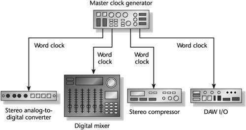
It is important to underscore that in digital studios, there can be only one master clock to control the clocks of the other digital devices. Uncompressed digital audio plays at a fixed rate. Although two or more devices in the signal chain can be set to run at the same sampling frequency, it is unlikely that the word clocks in each of these devices will run at the same time, which creates discontinuities in the audio streams.
Other ways to avoid jitter are to use balanced, well-shielded digital cables of the correct impedance; use short cables (longer cables are more subject to interference and data delays); keep digital and analog cables separate; and use the most accurate clock source as the master time reference if a master clock generator is not employed.
An audio driver is a program that allows the transfer of audio signals to and from an audio interface. Aside from its functionality in meeting needs, it is critical to select a driver with low latency (less than about 5 ms). Latency is the period of time it takes for data to get from one designated point to another. In audio, latency is the signal delay through the driver and the interface to the output. Some drivers have low latency; others have a moderate amount.
Latency does not in and of itself affect sound quality. The problem is with synchronization. Little or no latency in a digital system synchronizes the input and playback signals. The problem of latency can be avoided with audio interfaces that include the ability to mix incoming signals with already-recorded audio coming from the computer and then send the signal back out in sync.
Five frame rate standards are used within SMPTE time code: 23.976, 24, 25, 29.97, and 30 frames per second. Frame rate refers to the number of film or video frames displayed in 1 second of real time.
This is the frame rate used in high-definition video where the HD camera is substituting for film. The format is called 24p. The 24 refers to the standard frames-per-second rate used for film applications in the United States. The p stands for progressive, which refers to the scanning method used in producing a video picture. The audio recorder used with 24p, and with most audio production recording, runs at 30 fps. The discrepancy in the two different frame rates is resolved when picture and sound are transferred for post-production editing.
Some newer digital audio and video recorder/editors allow for 23.976 and 24p time code display and synchronization. Hence, there is no need for a conversion to 30 fps unless material is output to a television standard.
This is the frame rate used for pure film applications in the United States. Once a film is shot and transferred to a DAW for postproduction, 24 fps is not used.
To consider these two frame rates, it is first necessary to understand the implications of drop frame and non-drop frame.
In the days before color television, the frame rate of U.S. black-and-white TV was 30 fps. With color TV, the rate was reduced to 29.97 fps to allow easier color syncing of new programs and reproduction of black-and-white programs. Today, American television and videotape recorders run at 29.97 fps.
The problem with 30 fps time code running at 29.97 fps is that it comes up 108 frames short every hour. To correct this problem, a time code format called drop frame was developed. Drop frame skips the first two frame counts in each minute, except for each tenth minute (00, 10, 20, etc.), to force the time code to match the clock time.
Solving one problem, however, created another. A frame rate of 29.97 fps for, say, a 1-minute commercial will show as exactly 1 minute on a clock but will read 00:00:59:28 on a time code display. One hour of real time will read out as 00:59:56:12. In editing, not working with whole numbers can be bothersome, to say nothing of trying to get an exact program time in broadcasting. To resolve this problem, the 30 fps and 29.97 fps frame rates can be adjusted between drop frame and non-drop frame.
Drop frame is necessary when precise timing is critical and when synchronizing audio to video. But in most other production—audio and video—non-drop frame is used because it is easier to work with. It is worth remembering that recordings used in any given production must employ one mode or the other; the two modes are not interchangeable.
For the uses of the 29.97 fps and 30 fps codes in their drop frame and non-drop frame modes, see Figure 10-2. Given the array of frame rates in use and whether they are drop frame or non-drop frame, it is not uncommon during complex productions either to lose track of what was used and when or to misunderstand the requirements of a particular stage in the production chain. Some frame rates and counts are incompatible, such as 29.97 fps drop frame and non-drop frame. Others may be compatible in certain ways, such as 30 fps drop frame that can be converted to 29.97 fps drop frame in the process of transferring film and audio to a DAW. If possible, avoid mix-ups by using the frame rate and the frame count needed for the final delivery master throughout production and postproduction.
Table 10-2. 29.97 and 30 fps frame rates, counts, and their primary uses.
Frame Rate (fps) | Frame Count | Primary Uses |
|---|---|---|
29.97 | Non-drop frame | Postproduction editorial, original video production, and delivery masters for some nonbroadcast uses such as DVD-V |
29.97 | Drop frame | Delivery masters for broadcast and original video production on episodic television |
30 | Non-drop frame | Shooting film for music video or commercials for television at 24 fps or 30 fps |
30 | Drop frame | Used with 24 fps film origination of episodic or long-form television when the delivery master requirement is 29.97 drop frame |
From Tomlinson Holman, Sound for Film and Television, 2nd ed. (Boston: Focal Press, 2002), p. 144. | ||
Some digital recorder/editors differentiate between the drop frame and non-drop frame time code displays. Non-drop frame uses colons between the numbers—00:00:00:00, whereas drop frame uses semicolons—00;00;00;00. An easy way to remember is that dropping off the lower dot indicates the drop frame format.
Copying sound (or picture) from one audio (film or video) device to another is commonly called a transfer. The term dub, in popular use for decades and still in the audio lexicon, means essentially the same thing.
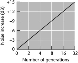
Analog-to-analog transfers are rarely done these days unless it is to preserve the sonic authenticity of a recording for archival purposes. In dubbing an analog recording from vinyl record to analog tape, each transfer of material loses a generation, worsening the signal-to-noise ratio (see Figure 10-3). Using only top-notch equipment and noise-reduction software that can act on such sounds as clicks, scratches, hum, rumble, hiss, and surface noise can minimize loss of audio quality. The loss in signal-to-noise ratio is more acute when transferring from vinyl record to analog tape than from analog tape to analog tape because the sound on a vinyl record is already several generations down due to the multigenerational steps in the mastering process.
In transferring material to open-reel analog tape, it is best to begin recording the sound a few seconds after the tape has started spinning to prevent the sound from wowing in— gradually reaching full speed. Even the finest analog open-reel audiotape recorders take at least one second to reach full speed. If the tape recorder has automated cueing, startup time is more precise and dependable.
Two primary considerations in transferring analog audio to digital audio are maintaining levels and not reducing dynamic range. Remember that if a signal goes “into the red” in analog recording, there is usually some headroom before distortion occurs. Once a signal is “in the red” with digital sound, it is already distorted. Therefore, in doing an analog-to-digital transfer, the first step is to do equipment calibration—adjust all levels to a standard so that their measurements are similar. For example, a reading of, say, 0 VU on the console should produce an equivalent reading of 0 VU or -20 dBFS digital signal level on the recorder(s).
In setting levels to avoid distortion and maintain dynamic range, one obvious approach is to set the level of the digital recorder at 0 VU during the loudest passages in the analog recording. This helps ensure that all levels will be 0 VU or below. In quiet passages, however, the level may be too low. For the sake of audibility, it may be necessary to use gentle compression to slightly raise the lower-level signal (see Chapters 11 and 13). Of course, any technique has to take into account the program material. Transferring classical music requires a different aesthetic than transferring rock music; dealing with dialog may not require as many sonic adjustments as dealing with the dynamics of sound effects.
Unless it is necessary, most signal processing is avoided in the transfer, or kept to a minimum, so as not to alter the original sound. This usually does not include transfers that are done to correct obvious audio deficiencies such as using EQ and compression to enhance the clarity of the original analog recording, especially if it is down a generation or more. Nor does it include taking advantage of the powerful noise-reduction capabilities of digital signal processing, which “clean” the sound without altering it (see Chapter 11).
Making a digital-to-digital transfer can be a straightforward process or—given the differences in quality among recording systems, the platforms they use, and susceptibility to digital errors—it can require some care. In any transfer of a digital signal from one digital device to another, the sampling frequency must be the same. If the sampling rate of the original recording is 48 kHz, for example, the mixer through which the signal is sent for transferring must also be set at 48 kHz.
In practice, though, when importing digital sources to a DAW, it is possible that the sampling rates of the various sources may be different. For example, the sample rate of a CD is 44.1 kHz; digital videotape is usually 48 kHz; Internet and multimedia audio might be 32 kHz or 22.050 kHz. By taking a few precautions, the havoc of sampling errors can be avoided. Try to use as few sampling-rate conversions as possible. Determine the final sampling rate and set the DAW to this rate. If the final sampling rate is 44.1 or 48 kHz, most DAWs can convert between these rates internally.
The number of bits (word length) transferred is not as important as the matching of sampling rates so long as the master (source) and the slave (destination) devices are using the same digital formats such as AES/EBU, S/PDIF, FireWire, and so on. That said, keeping the word length as long as possible during transfer helps reduce distortion: 24-bits is better than 16 bits. Moreover, feeding a 16-bit signal to a 24-bit device is more desirable than feeding a 24-bit signal to a 16-bit device. In the former instance, the 24-bit device will usually add zeros to fill out the digital word. In the latter instance, the last 8 bits are cut off, thereby introducing some distortion.
Other procedures worth noting in making digital transfers are as follows:
Digital audio data cables and word-clock lines need to be the same length. Cable length affects timing, which affects the phase relationship of the word clock to the digital audio data.
Make sure all signals—time code, digital audio, and word clock—are flowing from the source recording to the destination recording. Check signal flow and make sure there are no pops or clicks.
Avoid using wild time code during formatting. Wild time code occurs when the time code generator used for the original recording was not locked to the device that made the recording.
With tape, make sure that there is plenty of preroll and keep the transfer start point consistent.
Use high-quality digital audio cables.
Transferring a WAV, AIFF (Audio Interchange File Format), or Sound Designer II file, for example, rather than a digital audio signal, ensures a virtually perfect copy because it is an exact duplicate of the original file.
With FireWire, which has become the interface of choice, audio transfers over a computer connection are virtually trouble-free. This standardized high-speed connection not only can be used with audio, including multichannel, but with devices such as computers, hard drives, CD burners, digital video, and scanners. With FireWire, it now is possible to connect up to 63 devices. When a new bus bridge becomes available, it will be possible to connect more than 60,000 devices together on a common bus.
There are two standards of FireWire, 400 and 800. FireWire 400 has a maximum speed of 400 Mbits per second; 800 has a maximum speed of 800 Mbits per second. Three types of connectors are associated with FireWire: the four-pin found on devices such as video recorders and Windows PCs; the six-pin for Apples; and the nine-pin for FireWire 800. Maximum cable length is about 15 feet.
When a disk recorder is involved in a transfer either from within the computer from one hard-drive location to another or from one computer to another, the copy is exactly like the original. Digital tape-to-tape transfers or transfers to or from CD-Rs, CD-RWs, DVD-Rs, and the rewritable DVDs may or may not be exactly like the original due to digital errors and problems with error correction that may occur in the transfer process.
Transfers into a disk recorder usually involve either a file transfer or a streaming audio transfer. A file transfer is nonlinear and digital to digital. A streaming transfer is linear and may involve either analog or digital sources.
File transfers are done at higher than normal audio speeds. This cuts down the wait time compared with streaming audio transfers, which are in real time. Streaming audio transfers are also susceptible to digital bit errors; and if the error coding breaks down, interpolated data may be substituted into the missing portions, creating noticeable audio problems after several generations (see Figures 10-4 and 10-5).
Table 10-4. Audio file formats.
Formats | Applications and Characteristics |
|---|---|
AIFF (Audio Interchange File Format) | Created for use on Macintosh computers, but most professional PC programs can read and write AIFF files. Supports bit resolutions in multiples of 8, but most AIFF files are 16- to 24-bit. |
BWF (Broadcast Wave Format) | PC and Mac compatible. An enhanced WAV file that supports metadata. Files may be linear or lossy coded using MPEG-1 or MPEC-2. Adopted by the AES/EBU as a standard interchange. |
SDII (Sound Designer II) | Developed by Digidesign for use on Mac computers. Supports sampling frequencies up to 48 kHz by Digidesign and up to 96 kHz through MOTU (Mark of the Unicorn). |
WAV (Waveform) | Developed by Microsoft and accepted by most DAWs. Supports a variety of sampling rates and bit resolutions and a number of audio channels. |
Table 10-5. Project exchange formats.
Formats | Applications and Characteristics |
|---|---|
AAF (Advanced Authoring Format) | File interchange format designed for video postproduction and authoring. Transfers audio and video files. AAF is expected to replace OMF. Unlike MXF, AAF is designed to be used with works-in-progress. |
AES31 (Audio Engineering Society) | Supported by most DAWs but not Digidesign. Audio-only interchange. |
OMF 1 and 2 (Open Media Format) | Produced by Digidesign but interchanges with most DAWs. Transfers audio and picture files. |
MXF (Material Exchange Format) | Based on the AAF data model. Transfers audio and video files in a streamable format. MXF is used to transfer completed projects on a networked DAW. |
Synchronization provides the ability to lock two or more signals or devices so they operate at precisely the same rate.
Accurate synchronization requires a system to code the recording media and the controlling mechanisms to ensure signals remain in sync.
Of the various time codes available, two are mainly used today. SMPTE time code, which is the most employed, and MIDI time code.
SMPTE time code’s identifying code numbers are broken down into hours, minutes, seconds, and frames. Each encoded value is called a time code address.
MIDI time code (MTC) translates SMPTE time code into MIDI messages.
Computer-based recording/editing systems include one or more of the following time formats: real time, music time, film time, and MIDI time code.
Every digital audio system has a signal, known as a word clock (also called a sample clock or digital clock), generated inside the device that controls sampling frequency. It is an extremely stable synchronization signal used to control the rate at which digital audio data is converted or transmitted. With digital audio, sampling rate is the determining sync factor.
A degradation in the word-clock signals among the digital devices interfaced can create jitter—a variation in time from sample to sample that causes changes in the shape of the audio waveform.
An audio driver is a program that allows the transfer of audio signals to and from an audio interface.
It is critical to select a driver with low latency (less than about 5 ms). Latency is the period of time it takes for data to get from one designated point to another. In audio, latency is the signal delay through the driver and the interface to the output.
The problem of latency can be avoided with audio interfaces that include the ability to mix incoming signals with already-recorded audio coming from the computer and then to send the signal back out in sync.
Frame rate refers to the number of film or video frames displayed in 1 second of real time.
Five frame rate standards are used within SMPTE time code: 23.976, 24, 25, 29.97, and 30 frames per second (fps).
Frame rates are in either drop frame or non-drop frame format. Drop frame time code is time-accurate because it makes up for the error that results from the difference between the 29.97 fps and the 30 fps rate of video. Non-drop frame is the original video time code calculated at 30 fps. The two modes are not interchangeable.
Copying sound (or picture) from one audio (film or video) device to another is called a transfer or a dub.
Common audio transfers are analog to analog, analog to digital, and digital to digital.