
4
AN INTRODUCTION TO UML AND USE CASES

The Unified Modeling Language (UML) is a graphic-based developmental language used to describe requirements and standards for software design. The latest versions of the Institute of Electrical and Electronics Engineers (IEEE) SDD standard are built around UML concepts, so we’ll start by covering the background and features of UML before moving on to how the language implements use cases to help us represent software system designs clearly and consistently.
4.1 The UML Standard
UML started out in the mid-1990s as a collection of three independent modeling languages: the Booch method (Grady Booch), the object modeling technique (Jim Rumbaugh), and the object-oriented software engineering system (Ivar Jacobson). After this initial amalgamation, the Object Management Group (OMG) developed the first UML standard, with input from a multitude of researchers, in 1997. UML remains under OMG’s management today. Because UML was essentially designed by unification, it contains many different ways to specify the same thing, resulting in a lot of systemwide redundancy and inconsistency.
So why use UML? Well, despite its shortcomings, it’s a rather complete modeling language for object-oriented design. It’s also become the de facto IEEE documentation standard to use. So even if you don’t intend to use UML for your own projects, you’ll need to be able to read it when dealing with documentation from other projects. Because UML has become popular, there’s a good chance your project’s stakeholders are already familiar with it. It’s sort of like the C programming language (or BASIC, if you don’t know C): it’s ugly as far as language design goes, but everybody knows it.
UML is a very complex language that requires considerable study to master, an educational process that is beyond the scope of this book. Fortunately, dozens of good books are available on the subject, some almost 1,000 pages long (for example, The UML Bible by Tom Pender; see “For More Information” on page 88). This chapter and those that follow are not intended to make you an expert on UML, but rather to quickly cover the UML features and concepts that the rest of the book uses. That way, you can refer back to these chapters when you’re trying to make sense of UML diagrams later in the book.
With that brief introduction behind us, next we’ll discuss how UML enables us to visualize a system’s design in a standardized way.
4.2 The UML Use Case Model
UML specifies use cases to describe a system’s functionality. A use case roughly corresponds to a requirement. Designers create a use case diagram to specify what a system does from an external observer’s point of view, meaning they specify only what a system does, not how it does it. They’ll then create a use case narrative to fill in the details of the diagram.
4.2.1 Use Case Diagram Elements
Use case diagrams typically contain three elements: an actor, a communication link (or association), and the actual use case:
- Actors, typically drawn as stick figures, represent users or external devices and systems that use the system under design.
- Communication links are drawn as a line between an actor and a use case, and indicate some form of communication between the two.
- Use cases are drawn as ovals with an appropriate description and represent the activities the actors perform on the system.
Figure 4-1 shows an example of a use case diagram.
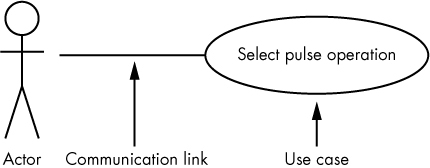
Figure 4-1: A sample use case diagram
Every use case should have a high-level name that concisely and uniquely describes the operation. For example, a nuclear reactor operator might want to select a power input from a nuclear power (NP) channel: “select %Pwr” is a general description, whereas “press the percent power button on the NP device” is probably too specific. How the user selects percent power is more of a design issue, not a system analysis issue (analysis is what we’re doing at this stage).
The use case name should be unique, because you’ll likely use it to associate the diagram with a use case narrative elsewhere in your UML documentation. One way to achieve uniqueness is by attaching a tag (see “Tag Formats” on page 172). However, the whole point of a use case diagram is to make the action obvious to the readers and stakeholders (that is, the external observers), and tags can obfuscate the meaning. One possible solution is to include a descriptive name (or phrase) and a tag inside the use case oval, as shown in Figure 4-2.

Figure 4-2: A use case tag combined with a user-friendly name
The tag uniquely identifies the use case narrative, and the user-friendly name makes the diagram easy to read and understand.
A use case diagram can contain multiple actors as well as multiple use cases, as shown in Figure 4-3, which provides use cases for generating Individual Megawatt Hour (MWH) and other reports.

Figure 4-3: Multiple actors and use cases in a use case diagram
Stick figures are useful for making it instantly obvious that you’re specifying an actor, but they have some drawbacks. First, a stick figure is rather large and can consume considerable screen (or page) space. Also, in a large and cluttered UML diagram, it can become difficult to associate names and other information with a stick figure actor. For this reason, UML designers often use a stereotype to represent an actor. A stereotype is a special UML name (such as “actor”) surrounded by guillemets (« and ») and enclosed along with the element’s name inside a rectangle, as shown in Figure 4-4. (You can use a pair of angle brackets—less-than and greater-than symbols—if you don’t have access to guillemets in your editing system.)

Figure 4-4: An actor stereotype
Stereotypes can apply to any UML element, not just an actor. The stereotype consumes less space and creates less clutter, though its disadvantage is that the type of element isn’t as instantly clear as it would be using the actual icon.1
4.2.2 Use Case Packages
You can assign use case names to different packages by separating the package name from the use case name using a pair of colons. For example, if the aforementioned reactor operator needs to select percent power from two different nuclear power systems (NP and NPP), we could use NP and NPP packages to separate these operations (see Figure 4-5).
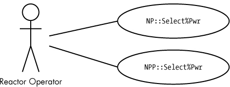
Figure 4-5: Package names in a use case
4.2.3 Use Case Inclusion
Sometimes, use cases will replicate information. For example, the use case in Figure 4-5 might correspond to a reactor operator selecting which nuclear power channel to use (the NP or NPP instrument) for a given operation. If the operator must verify that the channel is online before making the selection, presumably either of the use cases for NP::Select%Pwr and NPP::Select%Pwr would contain the steps needed to confirm this. When writing the narrative for these two use cases, you’ll probably discover that you’re duplicating considerable information.
To avoid this replication, UML defines use case inclusion, which allows one use case to completely include the functionality of another.
You specify use case inclusion by drawing two use cases with oval icons, and placing a dashed open arrow from the including use case to the included use case. Also attach the label «include» to the dashed arrow, as shown in Figure 4-6.

Figure 4-6: Use case inclusion
We could redraw Figure 4-5 using inclusion as shown in Figure 4-7.

Figure 4-7: Use case inclusion example
An inclusion is the use case diagram equivalent of a function call. Inclusion allows you to reuse a use case from other use cases, thereby reducing redundancy.
4.2.4 Use Case Generalization
Sometimes, two or more use cases share an underlying base design and build upon it to produce different use cases. Revisiting the example from Figure 4-3, the Sr. Reactor Operator actor might produce additional reactor reports (that is, “All reports”) beyond those that the Reactor Operator actor produces (“Individual MWH report”). However, both use cases are still an example of the more general “Generate reports” use case and, therefore, they share some common (inherited) operations. This relationship is known as use case generalization.
We can illustrate use case generalization in a use case diagram by drawing a hollow arrow from a specific use case to the more general use case, as shown in Figure 4-8.

Figure 4-8: Generalization of use cases
This figure tells us that the “Individual MWH report” and “All reports” use cases share some common activities inherited from the “Generate reports” use case.
We can generalize actors in the same fashion by drawing an open arrow from multiple (specific) actors to a generalized actor, as shown in Figure 4-9.

Figure 4-9: Generalization of actors
Generalization (particularly, use case generalization) is equivalent to inheritance in object-oriented systems. The hollow arrow points at the base use case, and the tail of the arrow (that is, the end without the arrowhead) connects to the inheriting, or derived, use case. In Figure 4-9, “Generate reports” is the base use case, and “Individual MWH report” and “All reports” are the derived use cases.
A derived use case inherits all the features and activities of the base use case. That is, all the items and functionality in the base use case are present in the derived use case, along with certain items unique to the derived use case.
In Figure 4-9, the Reactor Operator actor can select only an “Individual MWH report.” Therefore, any report generated by the Reactor Operator actor always follows the steps associated with that individual report. The Sr. Reactor Operator actor, on the other hand, can generate any report derived from the “All reports” or “Individual MWH report” use case.
Although generalization might seem very similar to inclusion, there are subtle differences. With inclusion a use case is completely included, but with inheritance the base use case is augmented by the features in the derived use case.
4.2.5 Use Case Extension
The UML use case extension allows you to specify the optional (conditional) inclusion of some use case. You draw an extension similar to an inclusion except you use the word «extend» rather than «include» and the arrow is a dashed line with a solid arrowhead. Another difference is that the arrowhead points at the extended use case, and the tail points at the extending use case, as shown in Figure 4-10.

Figure 4-10: Use case extension
Use case extensions are useful when you want to select one of several different use cases based on some internal system/software state. A classic example would be error or exception handling conditions. Suppose you have a small command line processor that recognizes certain commands beginning with a verb (such as read_digital). The command syntax might take the form:
read_digital port#
where port# is a numeric string indicating the port to read from. Two things could go wrong when the software processes this command: port# could have a syntax error (that is, it doesn’t represent a valid numeric value) or the port# value could be out of range. Thus, there are three possible outcomes from processing this command: the command is correct and reads the specified port; a syntax error occurs and the system presents an appropriate message to the user; or a range error occurs and the system displays an appropriate error message. Use case extensions easily handle these situations, as shown in Figure 4-11.

Figure 4-11: Use case extension example
Note that the normal case (no error) is not an extension use case. The read_port command use case handles the nonerror case directly.
4.2.6 Use Case Narratives
By themselves, the use case diagrams you’ve seen thus far don’t explain any details. An actual use case (as opposed to a use case diagram) is text, not graphics. The diagrams provide an “executive overview” of the use case and make it easy for external observers to differentiate activities, but the use case narrative is where you truly describe a use case. Although there is no defined set of items that appear in a use case narrative, it typically contains the information listed in Table 4-1.
Table 4-1: Use Case Narrative Items
Use case narrative item |
Description |
Associated requirements |
A requirements tag or other indication of the requirement(s) associated with the use case. This provides traceability to the SyRS and SRS documentation. |
Actors |
A list of the actors that interact with the use case. |
Goal/purpose/brief description |
A description of the goal (and its context within the system) to clarify the purpose of the use case. |
Assumptions and preconditions |
A description of what must be true prior to the execution of the use case. |
Triggers |
External events that start the execution of the use case. |
Interaction/Flow of Events |
The step-by-step description of how an external actor interacts with the system during the execution of the use case. |
Optional interactions/Alternative Flow of Events |
Alternative interactions from those the interaction steps describe. |
Termination |
Conditions that result in the termination of a use case. |
End conditions |
Conditions describing what happens when the use case successfully terminates or when it fails. |
Post conditions |
Conditions that apply upon completion of the execution of a use case (success or failure). |
Additional items (search online for descriptions) might include:2
- Minimal guarantees
- Successful guarantees
- Dialog (effectively another name for interactions)
- Secondary actors
- Extensions (another name for optional/conditional interactions)
- Exceptions (that is, error-handling conditions)
- Related use cases (that is, other relevant use cases)
- Stakeholders (people with an interest in the use case)
- Priority (among use cases for implementation)
4.2.6.1 Use Case Narrative Formality
Use case narratives can range in formality from casual to fully dressed.
A casual use case narrative is a natural language (for example, English) description of the use case without much structure. Casual narratives are ideal for small projects, and often vary from use case to use case.
A fully dressed use case narrative is a formal description of the use case, typically created via a form with all the narrative items defined for your project. A fully dressed use case narrative will likely consist of three forms:
- A list of the use case items, exclusive of the Dialog/Flow of Events/Interaction and Alternative Flow of Events/Optional Interactions items
- The main Flow of Events
- The Alternative Flow of Events (extensions)
Tables 4-2, 4-3, and 4-4 show an example of a fully dressed use case narrative.
Table 4-2: Select Nuclear Power Source, RCTR_USE_022
Requirement(s) |
RCTR_SyRS_022, RCTR_SRS_022_000 |
Actors |
Reactor Operator, Sr. Reactor Operator |
Goal |
To select the power measurement channel used during automatic operation |
Assumptions and preconditions |
Operator has logged in to the reactor console |
Trigger |
Operator presses appropriate button, selecting automatic mode power source |
Termination |
Operator-specified power source is selected |
End conditions |
System uses the selected power source for current actual power during automatic operation, if successful; system reverts to original auto-mode power source if unsuccessful |
Post condition |
System has an operational automatic-mode power source available |
Table 4-3: Flow of Events, RCTR_USE_022
Step |
Action |
1 |
Operator presses NP selection button |
2 |
System verifies that the NP is online |
3 |
System switches auto-mode power selection to the NP channel |
Table 4-4: Alternative Flow of Events (Extensions), RCTR_USE_022
Step |
Action |
2.1 |
The NP channel is not online |
2.2 |
The system doesn’t switch to using the NP power channel and continues to use the previously selected power channel for automatic mode |
4.2.6.2 Alternative Flow of Events
Whenever a step in the Flow of Events table contains a conditional or optional item (an extension in UML terminology), you’ll have some corresponding entries in the Alternative Flow of Events table that describe the behavior when the conditional item is false. Note that you don’t use a separate Alternative Flow of Events table for each condition; you simply use substeps (in this example, 2.1 and 2.2 in Table 4-4) associated with the step number(s) from the Flow of Events table (step 2 in Table 4-3).
This is just one possible example of a fully dressed use case narrative. Many other forms are possible. For example, you could create a fourth table to list all the possible end conditions, as shown in Table 4-5.
Table 4-5: End Conditions, RCTR_USE_022
Condition |
Result |
Success |
The NP channel is selected as the automatic-mode power channel |
Failure |
The previously selected channel continues to control automatic mode |
Adding an end conditions table is especially compelling if there are more than two end conditions.
As another example, consider the read_port use case in Figure 4-11. The narrative for it could be similar to Tables 4-6, 4-7, and 4-8.
Table 4-6: read_port Command
Requirement(s) |
DAQ_SyRS_102, DAQ_SRS_102_000 |
Actors |
PC host computer system |
Goal |
To read a digital data port on the data acquisition system |
Assumptions and preconditions |
Digital data acquisition ports have been initialized as input ports |
Trigger |
Receipt of the read_port command |
Termination |
Data port is read and the value returned to requesting system |
End conditions |
System returns port value or appropriate error message if the command was malformed |
Post condition |
The system is ready to accept another command |
Table 4-7: Flow of Events, read_port Command
Step |
Action |
1 |
The host PC sends a command line beginning with read_port |
2 |
System verifies that there is a second parameter |
3 |
System verifies that the second parameter is a valid numeric string |
4 |
System verifies that the second parameter is a numeric value in the range 0–15 |
5 |
System reads the digital data from the specified port |
6 |
System returns the port value to the host PC |
Table 4-8: Alternative Flow of Events (Extensions), read_port Command
Step |
Action |
2.1 |
Second parameter doesn’t exist |
2.2 |
System returns a “syntax error” message to the host PC |
3.1 |
Second parameter isn’t a valid numeric string |
3.2 |
System returns a “syntax error” message to the host PC |
4.1 |
Second parameter is outside the range 0–15 |
4.2 |
The system returns a “range error” message to the host PC |
Table 4-8 actually contains several independent flows of events. The major number to the left of the decimal point specifies the associated step in the Flow of Events table; the minor number to the right of the decimal point is the particular step within the Alternative Flow of Events. The flow occurs only within the steps associated with a single Flow of Events number. That is, the flow from 2.1 to 2.2 ends with 2.2; it doesn’t continue into 3.1 (in this example).
Generally, once a system selects an alternative flow (such as the “range error” flow, steps 4.1 and 4.2 in this example), the use case ends with the completion of that alternative flow (that is, at step 4.2). Control doesn’t return to the main Flow of Events. Execution to the end of the main Flow of Events list happens only if no alternative flows occur.
The “correct” way to use the Flow of Events and Alternative Flow of Events is to write a straight-line sequence representing the path through the use case that produces the intended result. If multiple viable paths exist, you would typically create multiple use cases, one for each correct path. The alternative flows handle any deviations (usually error paths) from the correct path. Of course, one risk of this approach is that you might wind up with an excessive number of use case diagrams.
For a Flow of Events, diagrams are more expensive to create and maintain than a textual description; even with the proper UML diagramming tools, creating figures generally takes more time and effort than just writing textual descriptions.
4.2.6.3 Conditional Flow of Events
For use cases that have multiple correct paths, you could encode those paths in the main Flow of Events using branches and conditionals, and leave the alternative paths for exceptional conditions. Consider a command for a data acquisition system that supports two different syntaxes:3
ppdio boards
ppdio boards boardCount
The first variant returns the number of PPDIO boards in the system, and the second variant sets the number of PPDIO boards. The technically correct solution to document these two commands is to create two separate use cases, each with its own Flow of Events. However, if the data acquisition system has dozens of different commands, creating individual use cases could clutter your documentation. One solution is to combine these use cases into a single use case by incorporating conditional operations (that is, if..else..endif) into a single Flow of Events, as in the following example.
Flow of Events
- Verify command begins with ppdio.
- Verify second word on command line is boards.
If no additional parameters appear on command line:
- Return number of PPDIO boards in system as response.
- Verify there is a single numeric parameter on the line.
- Verify that the numeric parameter is in the range 0..6.
- Set the number of PPDIO boards to the value specified by the numeric parameter.
Alternative Flows
1.1 If command doesn’t begin with ppdio, return not PPDIO response.
2.1 If command doesn’t begin with ppdio boards, return not PPDIO BOARDS response.
5.1 Return syntax error as the response.
6.1 Return range error as the response.
Having conditionals and multiple exit points from a Flow of Events isn’t “clean” UML; however, it can reduce the overall size of the documentation (saving time and expenses), so this is a common kludge in use cases.
You could even add while, for, switch, and other high-level-language–style operations to your Flow of Events. But keep in mind that use cases (and their descriptions) should be very general. Once you start embedding programming language concepts into your use cases, you invariably start introducing implementation details, which don’t belong in use cases; save those for later UML diagram types (such as activity diagrams).
These examples might seem to suggest that alternative flows are solely for error handling, but you can use them for other purposes as well; any time a conditional branch is out of a main flow, you can use extensions to handle that. However, one problem with using alternative flows for generic conditionals is that concepts that are inherently related wind up separated from one another in your use case descriptions, which can make following the logic in those descriptions more difficult.
4.2.6.4 Generalization vs. Extension
Generalization is often a better tool than extension. For example, suppose you have a generic port_command use case and you want to attach read_port and write_port to it. In theory, you could create an extension to handle this, as shown in Figure 4-12.

Figure 4-12: Poor example of use case extension
In practice, this particular situation is probably better handled with generalization, because read_port and write_port are special cases of a port_command (rather than being alternative branches from port_command). Figure 4-13 shows the generalization approach.
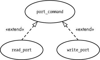
Figure 4-13: Using generalization rather than extension
With generalization, the derived use case follows all the steps in the base use case. When you use extensions, control transfers from the main Flow of Events to the Alternative Flow of Events, and any remaining steps in the main flow don’t happen.
4.2.7 Use Case Scenarios
A scenario is a single path through a use case. For example, the read_port use case has four scenarios: the success scenario when the command reads a port and returns the port data; two syntax error scenarios (2.1/2.2 and 3.1/3.2 in the Alternative Flow of Events); and one range error scenario (4.1/4.2 in the Alternative Flow of Events). You generate a full scenario by choosing the steps from the Flow of Events and Alternative Flow of Events that complete a specific path. The read_port command has the following scenarios:
Success scenario
- The host sends a command beginning with read_port.
- The system verifies that there is a second parameter.
- The system verifies that the second parameter is a numeric string.
- The system verifies that the second parameter is a value in the range 0..15.
- The system reads the data from the specified port.
- The system returns the port value to the host PC.
Syntax error #1 scenario
- The host sends a command beginning with read_port.
- The system determines there is no second parameter.
- The system sends a syntax error to the host PC.
Syntax error #2 scenario
- The host sends a command beginning with read_port.
- The system verifies that there is a second parameter.
- The system determines that the second parameter is not a legal numeric string.
- The system sends a syntax error to the host PC.
Range error scenario
- The host sends a command beginning with read_port.
- The system verifies that there is a second parameter.
- The system verifies that the second parameter is a numeric string.
- The system determines that the numeric string is a value outside the range 0..15.
- The system sends a range error to the host PC.
You can use scenarios to create test cases and test procedures for your system. You’ll have one or more test cases for each scenario.
You can combine use case scenarios by incorporating if statements in your Flow of Events. However, because this introduces low-level details into your use case narratives, you should avoid combining scenarios unless the number of use case narratives grows out of control.
4.3 The UML System Boundary Diagrams
When you’re drawing a simple use case diagram, it should be obvious which components are internal to the system and which are external. Specifically, actors are external entities, and the use cases are internal. If you’re using stereotyped rectangles instead of stick figures for the actors, though, it might not be immediately clear which components are external to the system. Also, if you reference multiple systems in a use case diagram, determining which use cases are part of which system can be challenging. UML system boundary diagrams solve these problems.
A UML system boundary diagram is simply a shaded rectangle surrounding the use cases that are internal to a particular system, as shown in Figure 4-14. The system title generally appears near the top of the rectangle.

Figure 4-14: A system boundary diagram
4.4 Beyond Use Cases
This chapter introduced UML uses cases, a very important feature of the Unified Modeling Language. However, there are many other components of UML beyond use cases. The next chapter presents UML activity diagrams, which provide a way to model actions within a software design.
4.5 For More Information
Bremer, Michael. The User Manual Manual: How to Research, Write, Test, Edit, and Produce a Software Manual. Grass Valley, CA: UnTechnical Press, 1999. A sample chapter is available at http://www.untechnicalpress.com/Downloads/UMM%20sample%20doc.pdf.
Larman, Craig. Applying UML and Patterns: An Introduction to Object-Oriented Analysis and Design and Iterative Development. 3rd ed. Upper Saddle River, NJ: Prentice Hall, 2004.
Miles, Russ, and Kim Hamilton. Learning UML 2.0: A Pragmatic Introduction to UML. Sebastopol, CA: O’Reilly Media, 2003.
Pender, Tom. UML Bible. Indianapolis: Wiley, 2003.
Pilone, Dan, and Neil Pitman. UML 2.0 in a Nutshell: A Desktop Quick Reference. 2nd ed. Sebastopol, CA: O’Reilly Media, 2005.
Roff, Jason T. UML: A Beginner’s Guide. Berkeley, CA: McGraw-Hill Education, 2003.
Tutorials Point. “UML Tutorial.” https://www.tutorialspoint.com/uml/.