
11
SOFTWARE DESIGN DESCRIPTION DOCUMENTATION

The Software Design Description (SDD) document provides low-level implementation details for the design of the software. While it doesn’t necessarily dive down to the level of actual code, it does provide the algorithms, data structures, and low-level flow control for the software implementation.
There are lots of different ideas about how to document software design. This chapter follows the guidelines proposed by IEEE Standard (Std) 1016-20091 and uses many of the concepts described in that standard.
IEEE Std 1016-2009 was written in an attempt to be language-independent. However, the Unified Modeling Language covers almost all of the requirements of the standard, which is why Chapter 4 introduced UML and why we’ll use it in this chapter. If you’re interested in the other software design modeling languages available, feel free to check out their descriptions in the IEEE Std 1016-2009 document.
11.1 IEEE Std 1016-1998 vs. IEEE Std 1016-2009
Finalized in 1998, the original IEEE SDD guidelines were based on structured programming software engineering concepts prevalent in the 1980s and 1990s. The recommendations were released just as the object-oriented programming revolution was under way and, as a result, immediately became outdated. It took 10 years to update, but the revision, Std 1016-2009, covered object-oriented analysis and design. The new guidelines maintained features of the 1016-1998 standard but in a somewhat deprecated form. Note, however, that some of them are still useful in modern design, so there’s no reason to ignore the old standard if those features are appropriate in your context.
11.2 IEEE 1016-2009 Conceptual Model
The SDD does not live in a vacuum. The material in an SDD flows naturally from the Software Requirements Specification (SRS), and the Reverse Traceability Matrix (RTM) binds the two documents. Figure 11-1 shows this relationship.
Figure 11-1: SRS relationship to SDD
11.2.1 Design Concerns and Design Stakeholders
Each requirement in the SRS ultimately relates to a design concern in the SDD (see Figure 11-2). A design concern is anything that is of interest to a stakeholder in the design of the system. A stakeholder is anyone who has a say in the system’s design. A requirement refers to any individual requirement from the SRS, as explained in Chapter 10.
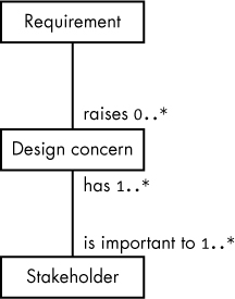
Figure 11-2: Mapping requirements to design concerns
Figure 11-2 maps requirements to design concerns as follows:
0..* Each requirement has zero or more associated design concerns.
1..* A single design concern is important to one or more design stakeholders.
1...* Each stakeholder has at least one (and possibly more) design concerns.
The IEEE conceptual model states that requirements raise zero or more design concerns. But in fact, requirements and design concerns should have a one-to-one relationship: for each design concern there is exactly one associated requirement. If a requirement doesn’t raise any design concerns—that is, the requirement has no impact on the software design—then perhaps that requirement isn’t necessary (and, therefore, is not a valid requirement). If a requirement maps to multiple design concerns, this probably suggests that you have a compound requirement that should be broken down into atomic requirements in your SRS (see “Atomic” on page 190).
Stakeholders and design concerns should have a many-to-many relationship. One stakeholder can (and usually does) have many design concerns. Likewise, a single design concern can be (and usually is) shared by many different stakeholders.
11.2.2 Design Viewpoints and Design Elements
Ultimately, the design concern (or just the requirement) is the interface point to the SDD. A design viewpoint logically groups a set of one or more design concerns. For example, a logical viewpoint (see “Logical Viewpoint” on page 235) would describe the static data structures in the design, so all the requirements associated with classes and data objects would be associated with that viewpoint. An algorithmic viewpoint (see “Algorithmic Viewpoint” on page 239) would describe certain algorithms that the design uses, so any requirements that specify certain algorithms to use (which, admittedly, should be rare) would be associated with that viewpoint.
IEEE Std 1016-2009 calls for specifying each design viewpoint by:
- A viewpoint name
- Design concerns associated with the viewpoint
- A list of design elements (types of design entities, attributes, and constraints) that the viewpoint uses
- A discussion of the analysis someone would use to construct a design view based on the viewpoint
- Criteria for interpreting and evaluating the design
- Author’s name or a reference to the source material used for the viewpoint
Figure 11-3 shows the relationship between design concerns and design viewpoints. The multiplicity item 1..* indicates that a single viewpoint frames (or groups) one or more requirements.

Figure 11-3: Mapping design concerns to design viewpoints
Design concerns and design viewpoints have a fundamental one-to-many relationship that provides traceability between the SDD and SRS. In the RTM, each requirement (design concern) will link to exactly one design viewpoint. Therefore, you would normally attach SDD tags to design viewpoints (or, as you’ll see in a moment, you could also attach the tags to design views, as there is a one-to-one relationship between design views and design viewpoints).
Design viewpoints define a set of design elements (see Figure 11-4), examples of which include class diagrams, sequence diagrams, state diagrams, packages, use cases, and activity diagrams.
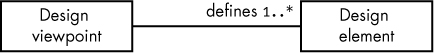
Figure 11-4: Mapping design viewpoints to design elements
A design element is anything that you would put in a design view, including design entities, attributes, relationships, and constraints:
- Design entities are objects that describe the major components of a design. Examples include systems, subsystems, libraries, frameworks, patterns, templates, components, classes, structures, types, data stores, modules, program units, programs, threads, and processes. IEEE Std 1016-2009 requires that each design entity in an SDD have a name and a purpose.
- Design elements have associated attributes: a name, a type, a purpose, and an author. When listing the design elements in your SDD viewpoint, you must provide these attributes.
- Design relationships have an associated name and type. IEEE Std 1016-2009 does not predefine any relationships; however, UML 2.0 defines several—such as association, aggregation, dependency, and generalization—that you would typically use in your SDDs. As per the IEEE requirements, you must describe all relationships you use in the design viewpoint specification.
- A design constraint is an element (the source element) that applies restrictions or rules to some other design element (the target element) of a design view. The IEEE requires that you list all design constraints by name and type (and source/target elements) in the viewpoint that defines them.
You define design elements using a formal design language (see Figure 11-5). As noted earlier, IEEE Std 1016-2009 tries to be language-agnostic, but the truth is that it was designed specifically around UML. Other (formal) design languages the IEEE suggests include IDEFO, IDEF1X, and Vienna Definition Method. However, for this book, you’re probably better off using UML.
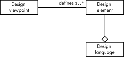
Figure 11-5: Relationship between design viewpoints, elements, and language
IEEE Std 1016-2009 defines a common set of design viewpoints. As the standard is a set of recommended practices, not absolute requirements, the list of viewpoints that follows here is neither exhaustive nor required. That is, in your SDD you can define and add further viewpoints as you see fit, and you don’t need to include all of them (indeed, some of them are deprecated and included only for compatibility with the older IEEE Std 1016-1998).
11.2.2.1 Context Viewpoint
The design elements for which the context viewpoint collects requirements are actors (users, external systems, stakeholders), services the system provides, and their interactions (such as input and output). The context viewpoint also manages various design constraints, such as quality of service, reliability, and performance. In a sense, you begin this work while developing the requirements for the SRS (for example, while creating use cases to drive the requirements) and finish the work while developing the SDD.
The main purpose of the context viewpoint is to set the system boundary and define those considerations that are internal to the system and those that are external. This limits the scope of the design so that the designer and author(s) of the SDD can concentrate on the system design and not waste time considering external factors.
You typically represent context viewpoints in UML use case diagrams (see “Use Cases” on page 214). For a good example, refer back to Figure 10-1, which lists the initializations the user can set via DIP switches on the data acquisition (DAQ) system. As another example, Figure 11-6 shows an abbreviated set of use cases for DAQ commands between a host system (typically a PC) and the DAQ CPU interface board.
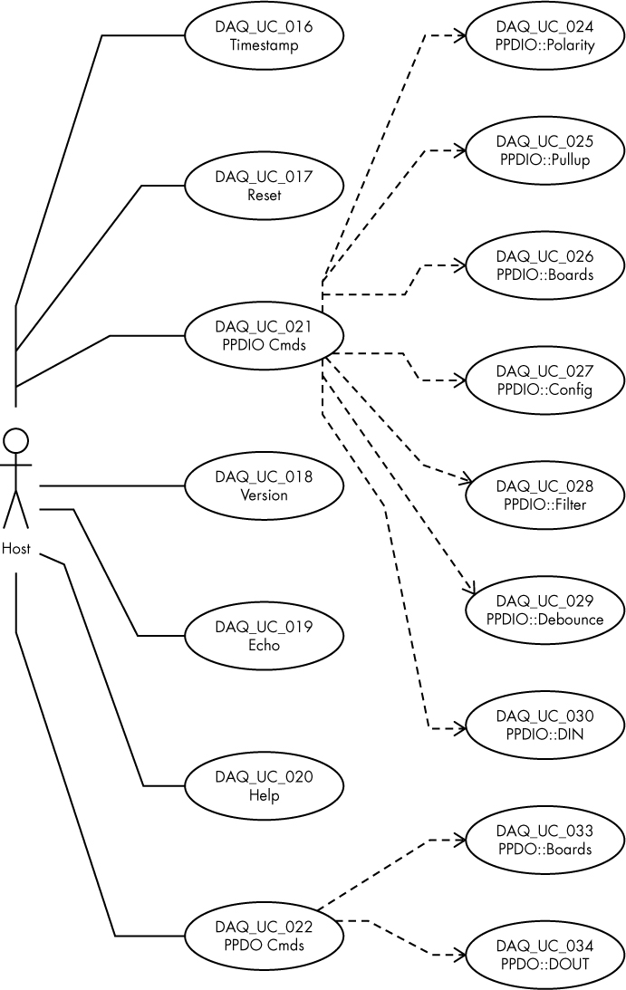
Figure 11-6: DAQ commands use case
This figure shows the command interface between the external system (the host actor) and the DAQ system. Note that each use case—in this example, there are 16—corresponds to requirements in the DAQ SRS.2
11.2.2.2 Composition Viewpoint
The composition viewpoint lists the major modules/components that make up the system. One of the main goals of this viewpoint is to foster code reuse by identifying, in the design, items that could come from existing libraries, or proprietary designs that could be reused in the system.
Design entities included in the composition viewpoint are—to name a few—composition (obviously), include, use, and generalization. The composition viewpoint states relationships between design entities using realization, dependency, aggregation, composition, and generalization as well as any other relationships between objects.
Note that this is an older viewpoint carried over from IEEE Std 1016-1998.3 For the most part it is superseded by the structure viewpoint (see “Structure Viewpoint” on page 237) and, to a lesser extent, the logical viewpoint (see the next section). The composition viewpoint hails from the days when programs were composed largely of procedures and functions organized into libraries, long before the days of object-oriented analysis and design.
Modern designs, if they contain a composition viewpoint at all, largely relegate it to describing major components of a system, as recommended by IEEE Std 1016-2009. Figure 11-7 provides an example of such a composition viewpoint for the DAQ system, using watered-down component diagrams. In my opinion, component diagrams are not a good fit for composition viewpoint diagrams—they are too low-level for the task. Component diagrams typically include interfaces (required and provided) that don’t make sense at the composition viewpoint level. However, apparently due to the similarity of the words composition and component, it’s very common to use watered-down UML component diagrams to denote the composition viewpoint.

Figure 11-7: Composition viewpoint diagram
Some engineers use a combination of component and deployment diagrams (see “Deployment Diagrams” on page 159) to illustrate a composition viewpoint, as shown in Figure 11-8.
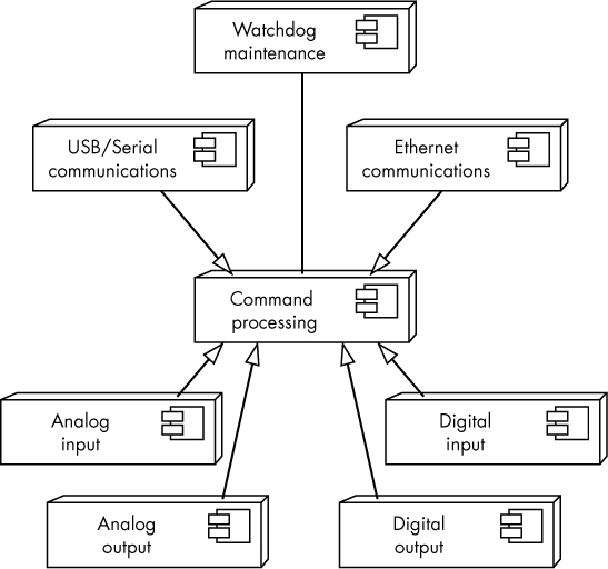
Figure 11-8: Deployment/component diagram
Note that the nodes in this diagram still include the component symbol to indicate that they are components forming a larger system, rather than hardware items. This is a nonstandard diagramming method for UML, but I’ve seen it in several example SDDs so I’ve included it here.
11.2.2.3 Logical Viewpoint
The logical viewpoint describes preexisting and new types used in the design, along with their class, interface/protocol, and structural definitions. The logical viewpoint also describes the objects (instances of the types) the design uses.
The logical viewpoint deals with classes, interfaces, data types, objects, attributes, methods, functions, procedures (subroutines), templates, macros, and namespaces. It also assigns attributes—such as names, visibility type, and values—and attaches appropriate constraints to these design entities.
Typically, you use UML class diagrams to implement a logical viewpoint. Figure 11-9 shows a class diagram for an adcClass_t class that might be appropriate for the analog input module in Figure 11-8. In addition to this basic class diagram, you’d probably want to include a data dictionary, or text describing the purpose of all the attributes for this class.

Figure 11-9: adc class diagram
In addition to the bare class diagrams, a logical viewpoint should also include relationships between classes (such as dependency, association, aggregation, composition, and inheritance). See “UML Class Relationships” on page 114 for more details on these class relationships and how you can diagram them.
11.2.2.4 Dependency Viewpoint
Like the composition viewpoint, the dependency viewpoint is a deprecated viewpoint maintained for compatibility with IEEE Std 1016-1998; you generally wouldn’t use this viewpoint in modern designs, as other options (such as the logical and resource viewpoints) can map dependencies in a more logical manner. However, there’s nothing stopping you from using dependency viewpoints where appropriate, and it’s also likely that you’ll encounter them in SDDs, so you should know about them.
In an SDD, the dependency viewpoint illustrates design entity relationships and interconnections, including shared information, interface parameterization, and order of execution using terms such as uses, provides, and requires. Dependency viewpoints apply to subsystems, components, modules, and resources. IEEE Std 1016-2009 recommends using UML component diagrams and package diagrams to depict this viewpoint. Using a combined deployment/component diagram (as in Figure 11-8) is probably a good solution if you want to go the component diagram route (say, for dependencies between components or subsystems). Using package diagrams is a good idea if you are describing the dependency relationship between packages, as shown in Figure 11-10.
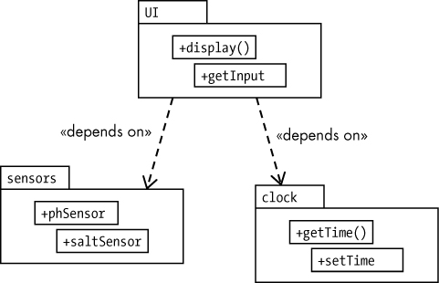
Figure 11-10: Package dependencies
11.2.2.5 Information/Database Viewpoint
The information/database viewpoint describes persistent data usage in your design. It is similar to the logical viewpoint in that you use class diagrams to show data structure, content, and metadata definitions. The information viewpoint would also describe data access schemes, data management strategies, and data storage mechanisms.
This is also a deprecated item included to maintain compatibility with IEEE Std 1016-1998. In modern designs, you would likely use the logical viewpoint or possibly the resource viewpoint instead.
11.2.2.6 Patterns Use Viewpoint
The patterns use viewpoint maps out the design patterns—and the reusable components implemented from them—that are used in the project. For more information about design patterns, see “For More Information” on page 260.
Patterns use viewpoint diagrams use a combination of UML composite structures, class diagrams, and package diagrams along with association, collaboration use, and connectors to indicate objects generated from the patterns. This viewpoint is loosely designed, so you have a lot of latitude in its creation should you choose to use it in your SDD.
11.2.2.7 Interface Viewpoint
The interface viewpoint describes the services (for example, APIs) provided by the design. Specifically, it includes a description of interfaces for which there are no requirements in the SRS, including interfaces to third-party libraries, other parts of the project, or other projects within the same organization. It is a road map that other programmers can use when interacting with the portion of the design covered by the interface viewpoint.
IEEE Std 1016-2009 recommends using UML component diagrams for the interface viewpoint. Figure 11-11 shows two components (possibly in the DAQ system) dealing with digital I/O and relay output (a specific form of digital output).

Figure 11-11: Interface viewpoint example
In addition to the component diagram, the interface viewpoint should include a description of how the system interacts with these interfaces, including data types, function calls, latencies, constraints on inputs, the range of outputs, and other important issues. For example, when discussing the Direction interface, you might include information such as:
Direction
Direction(ddir:int, port:int)
A call to Direction sets the specified digital I/O port (port = 0..95) to either an input port (if ddir = 0) or an output port (if ddir = 1).
For Read, you might use a description such as:
Read
Read(port:int):int
A call to Read returns the current value (0 or 1) of the specified digital input port (port = 0..95).
Again, the interface viewpoint is included in IEEE Std 1016-2009 only for compatibility with the older IEEE Std 1016-1998. In modern SDDs, consider placing interface items in the context and structure viewpoints instead.
11.2.2.8 Structure Viewpoint
The structure viewpoint describes the internal organization and construction of the objects in the design. It is the more modern version of the composition viewpoint, which describes how the design is (recursively) broken down into parts. You would use the structure viewpoint to break down larger objects into their smaller pieces for the purpose of determining how to reuse those smaller components throughout the design.
The diagramming methods typically used for the structure viewpoint are UML composite structure diagrams, UML package diagrams, and UML class diagrams. These diagrams are illustrated for the swimming pool monitor (SPM) in Figures 11-12, 11-13, and 11-14, respectively.

Figure 11-12: SPM composite structure diagram

Figure 11-13: SPM package diagram

Figure 11-14: SPM class diagram
These examples illustrate that you’ll typically have more than one diagram in a given viewpoint. Also note that a typical structure viewpoint will have multiple composite structure diagrams, (possibly) multiple package diagrams, and (certainly) multiple class diagrams.
11.2.2.9 Interaction Viewpoint
The interaction viewpoint is the main place where you define the activities that take place in the software. This is where you’ll place most of your interaction diagrams—activity diagrams, sequence diagrams, collaboration diagrams, and the like—with the possible exception of state diagrams, because they normally appear in the state dynamics viewpoint (covered in the next section). In addition to interaction diagrams, you might also use composite structure and package diagrams in the interaction viewpoint.
A full example of the interaction viewpoint appears in “A Sample SDD” on page 247.
11.2.2.10 State Dynamics Viewpoint
The state dynamics viewpoint describes the internal operating state of a software system. For this viewpoint, you would typically use UML statechart diagrams (see “Statechart Diagrams” on page 163).
11.2.2.11 Algorithmic Viewpoint
The algorithmic viewpoint is another older viewpoint carried over from IEEE 1016-1998. Its purpose was to describe the algorithms (typically through flowcharts, Warnier/Orr diagrams, pseudocode, and the like) used in the system. This viewpoint largely has been replaced by the interaction viewpoint in the Std 1016-2009 document.
11.2.2.12 Resource Viewpoint
The resource viewpoint describes how the design uses various system resources. This includes CPU usage (including multicore usage), memory usage, storage, peripheral usage, shared libraries, and other security, performance, and cost issues associated with the design. Typically, resources are entities that are external to the design.
This is another Std 1016-1998 item included for compatibility reasons in Std 1016-2009. In new designs, you would typically use the context viewpoint to describe resource usage.
11.2.3 Design Views, Overlays, and Rationales
IEEE Std 1016-2009 states that an SDD is organized into one or more design views. Therefore, the design view is the fundamental unit of organization in an SDD. Design views provide (possibly) multiple perspectives on the system design to help clarify to stakeholders, designers, and programmers how the design fulfills the requirements as specified by an associated design viewpoint.
An SDD is complete when it covers every requirement (design concern) in at least one design view, covers all the entities and relationships in the associated design viewpoint, and lives within all the constraints applied to the design. In plain terms, this means that you’ve matched all the requirements to appropriate diagrams and textual discussions as outlined in “Design Viewpoints and Design Elements” on page 229.
An SDD is consistent if there is no conflict between any of the elements in the design views. For example, if a class diagram states that an attribute (field) named hasValue is a boolean, but an activity diagram treats that field as a string, you have an inconsistency.
11.2.3.1 Design Views vs. Design Viewpoints
There is a one-to-one relationship between design view and design viewpoints, as shown in Figure 11-15. The association link states that a design view conforms to exactly one design viewpoint and a design viewpoint is governed by exactly one design view.

Figure 11-15: Design views and design viewpoints
So, what’s the difference between a design view and a design viewpoint? A design view is the actual information (graphic and textual) that you would normally consider to be the “design.” A design viewpoint is the point of view from which you create the design. In the IEEE recommendations, the design viewpoints would be something like the context viewpoint or interaction viewpoint. These are not the actual design views, but rather the format used to present the views. In terms of the organization of your SDD, the view/viewpoint section of the table of contents might look something like the following:4
1 Viewpoint #1
1.1 Viewpoint #1 Specification (see “Design Viewpoints and Design Elements” on page 229)
1.2 View #1
2 Viewpoint #2
2.1 Viewpoint #2 Specification
2.2 View #2
3 Viewpoint #3
3.1 Viewpoint #3 Specification
3.2 View #3
4 Etc.
The reason for organizing the views by viewpoints is simple: viewpoints represent the perspectives of different stakeholders, so this organization allows stakeholders to quickly locate the sections of the SDD of interest to them instead of having to read the whole document.
Note that each view in this outline does not necessarily correspond to a single diagram or textual description. A single view could consist of many separate UML diagrams and intervening textual descriptions. For example, in a logical viewpoint you’ll probably have many different class diagrams (not just one) if for no other reason than that it’s difficult to combine multiple classes into a single diagram. Even if you could, you might want to logically organize your class diagrams to make them easier to read. Furthermore, in addition to the class diagrams themselves, you’ll need to provide some text describing the members (attributes) of those classes. Rather than having a huge class diagram (perhaps consuming dozens of pages) followed by a very long textual description (spanning additional dozens of pages), it’s probably better to put a few class diagrams in one figure, immediately follow them with the textual information about the attributes, and then repeat this for the remaining classes you need to document.
11.2.3.2 Design Overlays
A design overlay is an “escape clause” for a view. Design views conform to design overlays or, conversely, design overlays govern design views, as shown in Figure 11-16. So, if you’ve created a logical viewpoint, for example, and you want to incorporate some interaction diagrams in that viewpoint for clarification, you would use a design overlay.
A design overlay modifies the view/viewpoint organization like so:
1 Viewpoint #1
1.1 Viewpoint #1 Specification
1.2 View #1
1.3 Overlay #1
1.4 Overlay #2
1.5 Etc.
2 Etc.
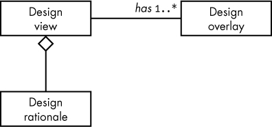
Figure 11-16: Design view/overlay/rationale relationship
Design overlays must be identified as such (to avoid confusion with the associated viewpoint), uniquely named, and associated with only a single viewpoint.
One benefit of a design overlay is that it lets you mix and match design languages or extend an existing design language when it isn’t expressive enough to satisfy your needs. Design overlays also allow you to extend an existing view without having to create a whole new viewpoint (which can be a lot of extra work).
11.2.3.3 Design Rationale
The design rationale explains the purpose behind the design and justifies the design to other viewers. Generally, a design rationale consists of comments and annotations throughout the design. It may address (but certainly isn’t limited to) potential concerns about the design, different options and tradeoffs considered during the design, arguments and justifications for why certain decisions were made, and even changes made during the prototyping or development phases (because the original design did not pan out). Figure 11-16 shows the relationship of design rationales to design views (the aggregation symbol implies that the design rationale comments are included, or are a part of, the design view).
11.2.4 The IEEE Std 1016-2009 Conceptual Model
Figures 11-17 and 11-18 provide conceptual model diagrams for the SDD and design elements, according to IEEE Std 1016-2009.5

Figure 11-17: SDD conceptual model

Figure 11-18: SDD design element conceptual model
11.3 SDD Required Contents
An SDD must have the following contents (according to IEEE Std 1016-2009):
- An SDD identification
- A list of the design stakeholders
- Design concerns (developed from the product requirements)
- A set of one or more design viewpoints (note that there’s exactly one design viewpoint for each design view in an SDD)
- A set of one or more design views (roughly corresponding to the different types of UML diagrams, though a design viewpoint is not necessarily tied to a particular UML diagram type)
- Any needed design overlays
- Any necessary design rationales (IEEE requires at least a purpose)
11.3.1 SDD Identification
At the very least, an SDD should include the following identification information (not necessarily in this order):
- Creation date/date of issue
- Current status
- Purpose/scope
- Issuing organization
- Authors (including copyright information)
- References
- Context
- A description of the design languages used for design viewpoints
- Body
- Summary
- Glossary
- Change history
Most of this information is boilerplate (except for dates, you typically copy this information from an organization’s generic SDD template). Obviously, some of this information changes from one SDD to another (like dates, authors, and change history), but for the most part very little intellectual activity is involved in the SDD identification. It exists primarily so that the SDD can stand as an independent document.
11.3.2 Design Stakeholders and Their Design Concerns
The SDD must list all the individuals who contributed requirements/design concerns to the project. This content is critical: if there is ever a question about the design rationale that is not addressed in the SDD, a reader should be able to determine which stakeholder to contact with questions about the design concerns.
11.3.3 Design Views, Viewpoints, Overlays, and Rationales
The design views, viewpoints, overlays, and rationales form the main body of the SDD.
11.4 SDD Traceability and Tags
We haven’t yet discussed how to trace design elements in an SDD back to the SRS and other system documents via the RTM (see “Traceability” on page 171). As noted in Chapter 9, you use tags to trace elements of the design throughout the documentation. For SDDs, you use tags of the form proj_SDD_xxx where proj is some project-specific name or mnemonic and xxx is a numeric (possibly decimal) value (see “SDD Tags” on page 176). All you have to do, then, is ensure you have unique SDD tags (generally by verifying that xxx is unique among all the SDD tags) and define where exactly to attach the SDD tags.
Technically, the requirements from the SRS map directly to the design concerns (one-to-one usually), which might tempt you to think that you should attach SDD tags to the design concerns. However, as the design views form the main body of the SDD and design concerns map to them in a many-to-one fashion (through the design viewpoints, which have a one-to-one relationship to design views), it’s best to attach SDD tags to the design views or viewpoints. It will make your life a whole lot easier when you’re creating the RTM if the mapping from the requirements to the design elements is either one-to-many or many-to-one (in particular, you want to avoid many-to-many).
In practice, a given design view can be broken down into multiple images or descriptions. If you are careful to only ever connect a design concern to one of these images or descriptions, you can assign SDD tags to the individual components of a design view. However, you must exercise caution when doing this, because if a single design concern maps to a couple of different components in a single design view, you can wind up with a many-to-many relationship.6
11.5 A Suggested SDD Outline
IEEE Std 1016-2009, Annex C, provides one suggested outline to organize and format an SDD that conforms to the required contents (see “SDD Required Contents” on page 244). Note that this outline is by no means a requirement; you can organize your SDD however you like and it will still be valid as long as it contains those required contents. The following is a slightly modified variant of the IEEE’s suggestion:7
1 Frontispiece
1.1 Table of Contents
1.2 Date of Issue and Status
1.3 Issuing Organization
1.4 Authorship
1.5 Change History
2 Introduction
2.1 Purpose
2.2 Scope
2.3 Intended Audience
2.4 Context
2.5 Overview/Summary
3 Definitions, Acronyms, and Abbreviations
4 References
5 Glossary
6 Body
6.1 Identified Stakeholders and Design Concerns
6.2 Design Viewpoint 1
6.2.1 Design View 1
6.2.2 (Optional) Design Overlays 1
6.2.3 (Optional) Design Rationales 1
6.3 Design Viewpoint 2
6.3.1 Design View 2
6.3.2 (Optional) Design Overlays 2
6.3.3 (Optional) Design Rationales 2
6.4 Design Viewpoint n
6.4.1 Design View n
6.4.2 (Optional) Design Overlays n
6.4.3 (Optional) Design Rationales n
7 (Optional) Index
11.6 A Sample SDD
This section presents a complete (though highly simplified, for editorial reasons) SDD example. This SDD describes the design for the sample use case and requirements documentation appearing in the previous chapter (see “Use Cases” on page 214). Specifically, this SDD covers the design of the Plantation Productions digital data acquisition and control (DAQ) system components that process the DIP switches upon system initialization.
1 Plantation Productions DAQ DIP Switch Control
1.1 Table of Contents
[Omitted for editorial reasons]
1.2 Date of Issue and Status
First created on Mar 18, 2018
Current status: complete
1.3 Issuing Organization
Plantation Productions, Inc.
1.4 Authorship
Randall L. Hyde
Copyright 2019, Plantation Productions, Inc.
1.5 Change History
Mar 18, 2019: Initial SDD created.
2 Introduction
2.1 Purpose
The DAQ system from Plantation Productions, Inc., is a digital data acquisition and control system intended to provide analog and digital I/O for industrial and scientific systems.
This Software Design Description (SDD) describes the DIP switch initialization component of the DAQ system. The intent is that a developer wishing to implement the functionality for the DIP switch control from the Software Requirement Specifications (SRS) can use this document to achieve that purpose.
2.2 Scope
This document describes only the DIP switch design in the DAQ system (for space/editorial reasons). For the full SDD, please see http://www.plantation-productions.com/Electronics/DAQ/DAQ.html.
2.3 Intended Audience
The intended audience expected for an SDD:
This document is intended for use by software developers who will implement this design, by design stakeholders who wish to review the design prior to its implementation, and by the authors of the Software Test Cases (STC) and Software Test Procedures (STD) documents.
The true intended audience for this SDD:
This document is intended for readers of Write Great Code, Volume 3, as a means for providing a sample SDD.
2.4 Context
The Plantation Productions DAQ system fulfilled a need for a well-documented digital data acquisition and control system that engineers could design into safety-critical systems such as nuclear research reactors. Although there are many commercial off-the-shelf (COTS) systems that could be used, they suffer from a couple of major drawbacks including: they are usually proprietary (difficult to modify or repair after purchase), they are often obsolete within 5 to 10 years with no way to repair or replace them, and they rarely have full support documentation (for example, SRS, SDD, STC, and STP) that an engineer can use to validate and verify the system.
The DAQ system overcomes this problem by providing an open hardware and open source set of designs with full design documentation that is validated and verified for safety systems.
Although originally designed for a nuclear research reactor, the DAQ system is useful in any place where you need an Ethernet-based control system supporting digital (TTL-level) I/O, optically isolated digital inputs, mechanical or solid-state relay digital outputs (isolated and conditioned), analog inputs (for example, ±10v and 4–20mA), and (conditioned) analog outputs (±10v).
2.5 Overview/Summary
The remainder of this documentation is organized as follows.
Section 3 covers the software design, including:
Section 3.1 Stakeholders and Design Concerns
Section 3.2 Context Viewpoint and Overall Architecture
Section 3.3 Logical Viewpoint and Data Dictionary
Section 3.4 Interaction Viewpoint and Control Flow
Section 4 provides an index.8
3 Definitions, Acronyms, and Abbreviations
Term |
Definition |
DAQ |
Data acquisition system |
SBC |
Single-board computer |
Software Design Description (SDD) |
Documentation of the design of the software system (IEEE Std 1016-2009)—that is, this document. |
Software Requirements Specification (SRS) |
Documentation of the essential requirements (functions, performance, design constraints, and attributes) of the software and its external interfaces (IEEE Std 610.12-1990). |
System Requirements Specification (SyRS) |
A structured collection of information that embodies the requirements of the system (IEEE Std 1233-1998). A specification that documents the requirements to establish a design basis and the conceptual design for a system or subsystem. |
4 References
Reference |
Discussion |
IEEE Std 830-1998 |
SRS documentation standard |
IEEE Std 829-2008 |
STP documentation standard |
IEEE Std 1012-1998 |
Software verification and validation standard |
IEEE Std 1016-2009 |
SDD documentation standard |
IEEE Std 1233-1998 |
SyRS documentation standard |
5 Glossary
DIP: Dual inline package
6 Software Design
6.1 Stakeholders and Design Concerns
The stakeholders for the DAQ DIP switch design are Plantation Productions, Inc., and Randall Hyde. One main design concern is to create a simplified SDD that fits within the editorial constraints of Write Great Code, Volume 3, while still providing a reasonable example of an SDD. The remaining design concerns are all the requirements for the DAQ DIP switch system as described in the SRS (see “(Selected) DAQ Software Requirements (from SRS)” on page 219).
6.2 Context Viewpoint and Overall Architecture
The DAQ context viewpoint shows the functionality that exists between the user and the system.
Name/tag: DAQ_SDD_001
Author: Randall Hyde
Design elements used: This viewpoint employs use cases, actors (host PC and end user), nodes, components, and packages to describe the system interface.
Requirements/design concerns:9
DAQ_SRS_700_000
DAQ_SRS_701_000
DAQ_SRS_704_000
DAQ_SRS_707_000
DAQ_SRS_723_000.1
6.2.1 Contextual View10
The DAQ system firmware runs on a Netburner MOD54415 SBC connected to a DAQ_IF (DAQ interface) board. An end user can set DIP switch settings to initialize the way the DAQ interfaces to a host PC. The host PC can communicate with the DAQ system using RS-232 Serial, USB, or Ethernet connections (see Figure 11-19). This design expects existing library routines for maintPrintf, serialTaskInit, usbTaskInit, ethernetTaskInit, and readDIPSwitches.
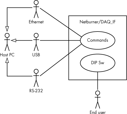
Figure 11-19: Sample contextual view
6.2.2 Component/Deployment Overlay
The following design overlay provides a different look at the contextual view using a combination deployment/component diagram. Figure 11-20 shows the physical components of the system11 and their interconnections.

Figure 11-20: Sample design overlay diagram
6.2.3 (Optional) Design Rationales
The purpose of this viewpoint is to show how the user controls the way in which the host PC communicates with the DAQ system.
6.3 Logical Viewpoint and Data Dictionary
Name/tag: DAQ_SDD_002
Author: Randall Hyde
Design elements used: This viewpoint employs a single class diagram to describe the data storage for this application.
NOTE
In the real application, it would probably be better to use global variables to hold the DIP switch settings rather than an actual class.
Requirements/Design Concerns:
DAQ_SRS_723_000.2
6.3.1 DIP Switch Variables
The data storage requirement for the DAQ (DIP switch) application is very simple. A set of 12 global variables in Figure 11-21 (which this SDD groups together under globals) is all that is really needed.
Name |
Description |
dipsw_g |
Eight-bit array (in a byte) containing DIP switch values |
serialEnable_g |
true if RS-232 communication is enabled |
USBEnabled_g |
true if USB communications is enabled |
ethEnabled_g |
true if Ethernet communications is enabled |
ethMultClients_g |
Allow only a single Ethernet client if false; allow five clients if true |
ethernetDipSw_g |
Hold dipsw_g[5] in bit 0 and dipsw_g[6] in bit 1 (0..3) |
unitTestMode_g |
true if operating in unit test mode |
debugMode_g |
true if maintPrintf() function sends output to COM1:, false if maintPrintf()is disabled |
ethernetAdrs_g |
Holds IP address (192.168.2.70–192.168.2.73) |
maxSockets_g |
Either 0, 1, or 5 based on ethEnabled_g and ethMultClients_g values |
slots_g |
Holds file descriptors for up to five active Ethernet sockets |
slot_g |
Used to index into slots_g |
maintPrintfTask() |
External function that starts the maintPrintf() task (to handle debug output) |
serialTaskInit() |
External function that starts the RS-232 command receipt task |
usbTaskInit() |
External function that starts the USB command receipt task |
ethTaskInit() |
External function that starts an Ethernet command receipt task (up to five of these threads can be running concurrently) |
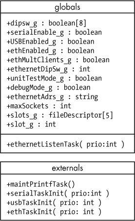
Figure 11-21: DAQ global entities
6.3.2 Design Overlays
[None]
6.3.3 Design Rationales
This logical view used a class diagram rather than a set of global variables simply because a typical read dipswitches function for the Netburner returns all eight readings in a single 8-bit byte (that is, as a bit array). For that reason, it makes sense to treat all eight values as fields of a class, as these attributes would normally be derived anyway—that is, computed by masking out the specific bit.
6.4 Interaction Viewpoint and Control Flow
Name/tag: DAQ_SDD_003
Author: Randall Hyde
Design elements used: This viewpoint employs a couple of activity diagrams to show the control flow (and the value calculations) through the program.
Requirements/design concerns:
DAQ_SRS_702_000
DAQ_SRS_702_001
DAQ_SRS_702_002
DAQ_SRS_703_000
DAQ_SRS_703_001
DAQ_SRS_705_000
DAQ_SRS_705_001
DAQ_SRS_705_002
DAQ_SRS_706_000
DAQ_SRS_706_001
DAQ_SRS_708_000
DAQ_SRS_709_000
DAQ_SRS_710_000
DAQ_SRS_711_000
DAQ_SRS_712_000
DAQ_SRS_716_000
DAQ_SRS_716_001
DAQ_SRS_716_002
DAQ_SRS_716.5_000
DAQ_SRS_717_000
DAQ_SRS_718_000
DAQ_SRS_718_001
DAQ_SRS_719_000
DAQ_SRS_720_000
DAQ_SRS_721_001
DAQ_SRS_721_002
DAQ_SRS_723_000
DAQ_SRS_723_000
DAQ_SRS_723_000
DAQ_SRS_723_000.2
DAQ_SRS_726_000
DAQ_SRS_727_000
DAQ_SRS_728_000
DAQ_SRS_737_000
DAQ_SRS_738_000
DAQ_SRS_738_001
DAQ_SRS_738_002
6.4.1 Design View
The design view for the interaction viewpoint uses UML activity diagrams (flowcharts) to show the control flow through the application. See Figures 11-22, 11-23, and 11-24.
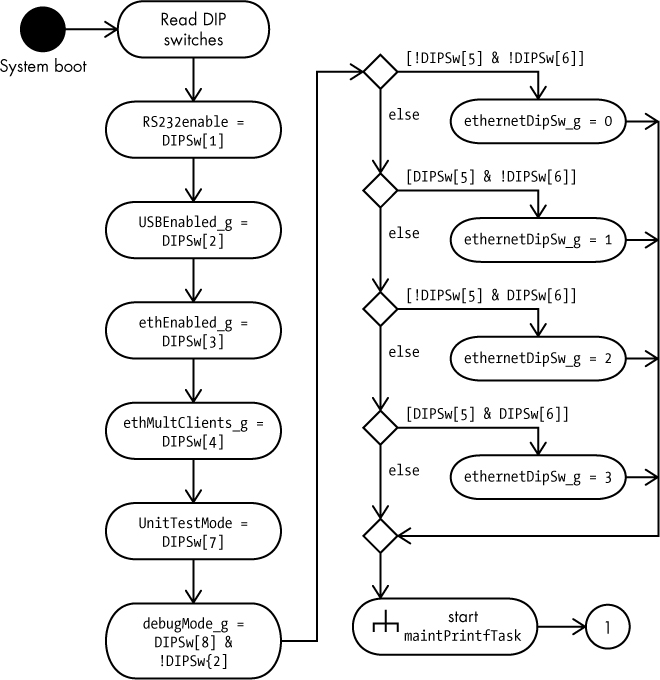
Figure 11-22: Activity diagram: reading DIP switches

Figure 11-23: Activity diagram continuation #1

Figure 11-24: Activity diagram continuation #2
The serialTaskInit() and usbTaskInit() functions are library code that is external to this design. These functions start a task, ethernetListenTask, to handle RS-232 and USB communications as shown in Figure 11-25.
The ethTaskInit() function (provided in a library external to this design) runs until the connecting host terminates the Ethernet connection. At that time, the ethernetListenTask task will set the entry of the corresponding slots to 0 and terminate the task (thread). Should the listen connection become broken, ethernetListenTask terminates.
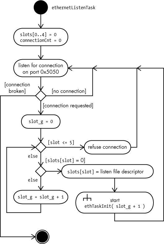
Figure 11-25: Activity diagram: ethernetListenTask
6.4.2 Sequence Diagram Overlay
The sequence diagram in Figure 11-26 shows another way of looking at the initialization of the threads in the DAQ application.
6.4.3 Design Rationale
The DAQ DIP switches project is relatively simple (purposely, so that the SDD example wouldn’t be too large to fit into this book). Accordingly, the design is an old-fashioned procedural/imperative programming model (as opposed to an object-oriented design).
7 Index
[Omitted for editorial reasons]

Figure 11-26: Sequence diagram: initializing tasks
11.7 Updating the Traceability Matrix with Design Information
The SDD adds a single column to the RTM: the SDD tag column. However, the SDD tag does not directly embed any traceability information, so you’ll have to extract that information from the SDD to determine where to place your SDD tags in the RTM.
As noted in “Design Views vs. Design Viewpoints” on page 240, each viewpoint in an SDD must include design concerns and requirements information. In this chapter (see “A Sample SDD” on page 247), I’ve strongly suggested supplying all the SRS requirement tags as the list of design concerns in the viewpoint documentation. If you’ve done that, you’ve already created the reverse traceability back to the requirements. As a result, filling in the SDD tags in the RTM is easy: just locate each requirement tag (listed in the current viewpoint) and copy the viewpoint’s SDD tag into the SDD tag column in the RTM. Of course, considering that you can have multiple requirements associated with a single viewpoint, you’ll also have several copies of the same SDD tag spread throughout the RTM (one per associated requirement).
Should you ever want to trace your SDD tags back to all the requirements in the RTM (without looking up the list in the SDD), simply sort the RTM by the SDD tag column. This will collect all the requirements (and everything else linked to that SDD tag) into a contiguous group in the matrix and make it easy to identify everything associated with that tag.
If you choose some other method of specifying design concerns in the viewpoint that doesn’t involve incorporating the SRS tags within them, then determining the placement of the SDD tags in the RTM becomes a manual (even laborious) process. That’s why I strongly recommend using SRS tags when generating your viewpoints. Since you have to consider all the requirements when generating the viewpoint anyway, it makes sense to collect that information into the SDD at the same time.
11.8 Creating a Software Design
This chapter has spent considerable time discussing how to create a Software Design Description. In the examples you’ve seen, it might seem that the actual designs were plucked out of thin air. Where did these designs originate from? If you’re creating a new system design, how do you come up with that design in the first place? Well, that’s the subject of the next volume in this series, Write Great Code, Volume 4: Designing Great Code. This chapter has laid the groundwork for that book.
11.9 For More Information
Freeman, Eric, and Elizabeth Robson. Head First Design Patterns: A Brain-Friendly Guide. Sebastopol, CA: O’Reilly Media, 2004.
Gamma, Erich, et al. Design Patterns: Elements of Reusable Object-Oriented Software. Upper Saddle River, NJ: Addison-Wesley Professional, 1994.
IEEE. “IEEE Std 1016-2009: IEEE Standard for Information Technology—Systems Design—Software Design Descriptions.” July 20, 2009. https://ieeexplore.ieee.org/document/5167255/. (It’s not cheap—about $100—and it’s worded in a way that only a lawyer can appreciate, but this is the gold standard for SDDs.)