
7
UML INTERACTION DIAGRAMS

Interaction diagrams model the operations that occur between different objects (participants) in a system. There are three main types of interaction diagrams in UML: sequence, collaboration (communication), and timing. The majority of this chapter will focus on sequence diagrams, followed by a very brief discussion of collaboration diagrams.
7.1 Sequence Diagrams
Sequence diagrams show the interaction between participants (actors, objects) in the order in which it takes place. Whereas activity diagrams describe the particulars of one operation on an object, sequence diagrams tie activity diagrams together to show the order in which multiple operations occur. From a design perspective, sequence diagrams are more informative than activity diagrams as they illustrate the overall architecture of the system; at the (lower) level of an activity diagram, however, a system architect can usually safely assume that the software engineer implementing the system can figure out the activities required by the design.
7.1.1 Lifelines
At the top of a sequence diagram you draw the set of participants, using rectangles or stick figures (see Figure 7-1), and then draw a dashed line from each participant to the bottom of the diagram to indicate that object’s lifeline. Lifelines show the flow of time from the earliest (topmost) point of execution to the latest (bottommost) point. However, lifelines by themselves do not indicate the amount of time that passes, only the passage of time from the top to the bottom of the diagram, and equal line lengths need not correspond to the same amount of time—a 1 cm section at one point could be days, while a 1 cm section elsewhere could be microseconds.

Figure 7-1: A basic sequence diagram
7.1.2 Message Types
Communication between participants takes the form of messages (which I will sometimes call operations), which consist of an arrow drawn between lifelines, or even from one lifeline to itself.
There are four types of message arrows you can use, as shown in Figure 7-2.
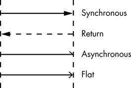
Figure 7-2: Message types in sequence diagrams
Synchronous messages are the typical call/return operation that most programs use (to execute object methods, functions, and procedures). The sender suspends execution until the receiver returns control.
Return messages indicate that control returns from a synchronous message back to the message sender, but they are purely optional in a sequence diagram. An object cannot continue execution until a synchronous message completes, so the presence of some other message (received or sent) on the same timeline inherently implies a return operation. Because a large number of return arrows can obfuscate a sequence diagram, it’s best to leave them off if the diagram starts to get cluttered. If the sequence diagram is relatively clean, however, a return arrow can help show exactly what is happening.
Asynchronous messages trigger an invocation of some code in the receiver, but the message sender does not have to wait for a return message before continuing execution. For this reason, there’s no need to draw an explicit return arrow for an asynchronous call in your sequence diagrams.
Flat messages can be either synchronous or asynchronous. Use a flat message when the type doesn’t matter for the design and you want to leave the choice up to the engineer implementing the code. As a general rule, you do not draw return arrows for flat messages because that would imply that the implementer must use a synchronous call.
NOTE
Flat messages are UML 1.x entities only. In UML 2.0, asynchronous messages use the full open arrowhead instead.
7.1.3 Message Labels
When you draw a message, you must attach a label to the message’s arrow. This label could simply be a description of the message, as in Figure 7-3.
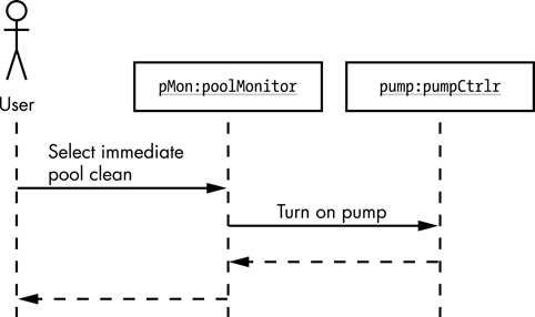
Figure 7-3: Message labels
The sequence of messages is indicated by their vertical placement. In Figure 7-3, the “Select immediate pool clean” label is the first message line in the diagram, meaning it is the first operation to execute. Moving downward, “Turn on pump” is the second message line, so it executes next. The return from “Turn on pump” is the third operation and the return from “Select immediate pool clean” is the fourth.
7.1.4 Message Numbers
As your sequence diagrams become more complex, it may be difficult to determine the execution order from the message position alone, so it can be helpful to attach additional indicators like numbers to each message label. Figure 7-4 uses sequential integers, though UML doesn’t require this. You could use numbers like 3.2.4 or even non-numeric indicators (for example, A, B, C). However, the goal is to make it easy to determine the message sequence, so if you get too carried away here you might defeat that purpose.

Figure 7-4: Message numbers
Although the message labels you’ve seen thus far are relatively straightforward descriptions, it’s not uncommon to use the actual operation names, parameters, and return values as labels on message arrows, as in Figure 7-5.

Figure 7-5: Message arguments and return values
7.1.5 Guard Conditions
Your message labels can also include guard conditions: Boolean expressions enclosed in brackets (see Figure 7-6). If the guard expression evaluates to true, the system sends the message; if it evaluates to false, the system does not send the message.

Figure 7-6: Message guard conditions
In Figure 7-6, the pMon object sends a pump(100) message to pump only if pumpPower is on (true). If pumpPower is off (false) and the pump(100) message does not execute, the corresponding return operation (sequence item 3) will not execute either, and control will move to the next outgoing arrow item in the pMon lifeline (sequence item 4, returning control to the user object).
7.1.6 Iterations
You can also specify the number of times a message executes by providing an iteration count in a sequence diagram. To specify an iteration, you use an asterisk symbol (*) followed by a guard condition or for loop iteration count (see Figure 7-7). The system will repeatedly send the message as long as the guard condition is true.
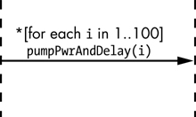
Figure 7-7: Partial sequence diagram with iteration
In Figure 7-7, the message executes 100 times, with the variable i taking on the value 1 through 100, incrementing on each iteration. If the pumpPwrAndDelay function applies the percent power specified as the argument and delays for 1 second, then in about 1 minute, 40 seconds, the pump will be running at full speed (increasing by 1 percent of the total speed each second).
7.1.7 Long Delays and Time Constraints
Sequence diagrams typically describe only the order of messages, not the amount of time each message takes to execute. Sometimes, however, a designer might want to indicate that a particular operation might take a long time relative to others. This is particularly common when one object sends a message to another object located outside the bounds of the current system (for example, when a software component sends a message to some object on a remote server across the internet), which we’ll discuss shortly. You indicate that an operation will take longer by pointing the message arrow slightly downward. In Figure 7-8, for example, you would expect the scheduledClean() operation to take more time than a typical operation.
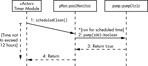
Figure 7-8: Timed messages with timing constraints
You must also specify the expected amount of time for each message by adding some sort of constraint to the diagram. Figure 7-8 demonstrates this with a dashed vertical arrow from the start of the scheduledClean() operation to the point on the lifeline where the system returns control to the Timer Module actor (probably the physical timer on the pool monitor system). The required time constraint appears inside braces next to the dashed arrow.
7.1.8 External Objects
Occasionally a component of a sequence diagram must communicate with some object external to the system. For example, some code in the pool monitor might check the salinity level and send an SMS message to the owner’s cell phone if it drops too low. The code to actually transmit the SMS message is probably handled by an Internet of Things (IoT) device and thus outside the scope of the pool monitor software; hence, the SMS code is an external object.
You draw a heavy border around external objects and use a solid line for their lifelines rather than a dashed line (see Figure 7-9).

Figure 7-9: External objects in a sequence diagram
In Figure 7-9, the Timer Module makes an asynchronous call to the salinity object, and there is no return from the salinityCheck() operation. After that call, the Timer Module can perform other tasks (not shown in this simple diagram). Ten minutes later, as noted by the time constraint, the salinity object makes an asynchronous call to the Timer Module actor and has it update the salinity value on the display.
Because there isn’t an explicit time constraint on the sendMsg() operation, it could occur any time after the salinityCheck() operation and before the updateSalinityDisp() operation; this is indicated by the sendMsg() message arrow’s position between the other two messages.
7.1.9 Activation Bars
Activation bars indicate that an object is instantiated and active, and appear as open rectangles across a lifeline (see Figure 7-10). They are optional, as you can generally infer the lifetime of an object simply by looking at the messages traveling to and from it.

Figure 7-10: Activation bars
NOTE
For the most part, activation bars clutter up sequence diagrams, so this book will not use them. They’re described here just in case you encounter them in sequence diagrams from other sources.
7.1.10 Branching
As noted in “Guard Conditions” on page 131, you can apply guard conditions to a message that say, effectively, “if true, then execute message; else, continue along this lifeline.” Another handy tool is branching—the equivalent of the C-style switch/case statement where you can select one of several messages to execute based on a set of guard conditions, one guard for each message. In order to execute different messages based on whether a pool uses chlorine or bromine as a sanitizer, you might be tempted to draw branching logic as shown in Figure 7-11.

Figure 7-11: Bad implementation of branching logic
In one aspect, this diagram makes perfect sense. If the sanitizer for this particular pool is bromine rather than chlorine, the first message does not execute and control flows down to the second message, which does execute. The problem with this diagram is that the two messages appear at different points on the lifeline and, therefore, could execute at completely different times. Particularly as your sequence diagrams get more complex, some other message invocation could wind up between these two—and thus would execute prior to the getBromine() message. Instead, if the sanitizer is not chlorine you’d want to immediately check to see if it is bromine, with no possibility of intervening messages. Figure 7-12 shows the proper way to draw this logic.

Figure 7-12: Good implementation of branching logic
Drawing branching logic with the arrow tails that start from the same vertical position and the arrowheads that end at the same vertical position avoids any ambiguity with the sequence of execution (assuming that the guard conditions are mutually exclusive—that is, it is not possible for both conditions to be simultaneously true).
Branching uses slanted message arrows similar to long delays, but a long delay item will have an associated time constraint.1
7.1.11 Alternative Flows
There’s another potential issue with branching: what happens when you need to send one of two different messages to the same destination object? Because the arrow tails and heads must start and end, respectively, at the same vertical positions for both arrows, the two arrows would overlay each other and there would be no indication that branching takes place at all. The solution to this problem is to use an alternative flow.
In an alternative flow, a single lifeline splits into two separate lifelines at some point (see Figure 7-13).
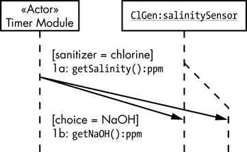
Figure 7-13: Alternative flows
In this example, the Timer Module has to choose between retrieving the current level of salinity (NaCl) or sodium hydroxide (NaOH). The getSalinity() and getNaOH() operations are methods within the same class; therefore, their message arrows will both point at the same spot in the ClGen lifeline. To avoid overlapping the message arrows, Figure 7-13 splits the ClGen lifeline into two lifelines: the original and an alternative flow.
After the message invocation, you can merge the two flows back together if desired.
7.1.12 Object Creation and Destruction
So far in the examples, the objects have existed throughout the lifetime of the sequence diagram; that is, all objects existed prior to the execution of the first message (operation) and persist after the execution of the last message. In real-world designs, you’ll need to create and destroy objects that don’t exist for the full duration of the program’s execution.
Object creation and destruction are messages just like any other. The common convention in UML is to use the special messages «create» and «destroy» (see Figure 7-14) to show object lifetimes within the sequence diagram; however, you can use any message name you like. The X at the end of the cleanProcess lifeline, immediately below the «destroy» operation, denotes the end of the lifeline, because the object no longer exists.
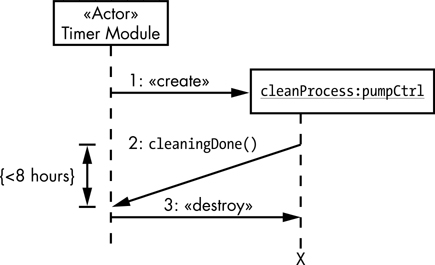
Figure 7-14: Object creation and destruction
This example uses a dropped title box to indicate the beginning of the lifeline for a newly created object. As Russ Miles and Kim Hamilton point out in Learning UML 2.0 (O’Reilly, 2003), many standardized UML tools don’t support using dropped title boxes, allowing you to place the object title boxes only at the top of the diagram. There are a couple of solutions to this problem that should work with most standard UML tools.
You can put the object at the top of the diagram and add a comment to explicitly indicate object creation and destruction at the points where they occur (see Figure 7-15).

Figure 7-15: Using notes to indicate object lifetime
You can also use an alternative flow to indicate the lifetime of the object (see Figure 7-16).
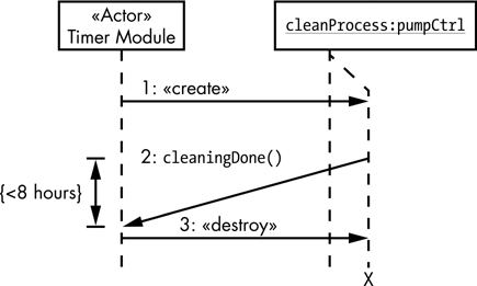
Figure 7-16: Using alternative flows to indicate object lifetime
Activation bars provide a third alternative that might be clearer here.
7.1.13 Sequence Fragments
UML 2.0 added sequence fragments to show loops, branches, and other alternatives, enabling you to better manage sequence diagrams. UML defines several standard sequence fragment types you can use, defined briefly in Table 7-1 (full descriptions appear later in this section).
Table 7-1: Brief Descriptions of Sequence Fragment Types
alt |
Executes only the alternative fragment that is true (think of an if/else or switch statement). |
assert |
Notes that operations within the fragment are valid if a guard condition is true. |
break |
Exits a loop fragment (based on some guard condition). |
consider |
Provides a list of valid messages in a sequence fragment. |
ignore |
Provides a list of invalid messages in a sequence fragment. |
loop |
Runs multiple times and the guard condition determines whether the fragment repeats. |
neg |
Never executes. |
opt |
Executes only if the associated condition is true. Comparable to alt with only one alternative fragment. |
par |
Runs multiple fragments in parallel. |
ref |
Indicates a call to another sequence diagram. |
region |
(Also known as critical.) Defines a critical region in which only one thread of execution is possible. |
seq |
Indicates that operations (in a multitasking environment) must occur in a specific sequence. |
strict |
A stricter version of seq. |
In general, you draw sequence fragments as a rectangle surrounding the messages, with a special penta-rectangle symbol (a rectangle with the lower-right corner cropped) in its upper-left corner that contains the UML fragment name/type (see Figure 7-17; substitute any actual fragment type for typ in this diagram).

Figure 7-17: Generic sequence fragment form
For example, if you wanted to repeat a sequence of messages several times, you would enclose those messages in a loop sequence fragment. This tells the engineer implementing the program to repeat those messages the number of times specified by the loop fragment.
You can also include an optional additional info item, which is typically a guard condition or iteration count. The following subsections describe the sequence fragment types from Table 7-1 in detail, as well as any additional information they may require.
7.1.13.1 ref
There are two components to a ref sequence fragment: the UML interaction occurrence and the reference itself. An interaction occurrence is a stand-alone sequence diagram corresponding to a subroutine (procedure or function) in code. It is surrounded by a sequence fragment box. The penta-rectangle in the upper-left corner of the box contains sd (for sequence diagram) followed by the name of the ref fragment and any arguments you want to assign to it (see Figure 7-18).
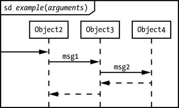
Figure 7-18: An interaction occurrence example
The leftmost incoming arrow corresponds to the subroutine entry point. If this isn’t present, you can assume that control flows to the leftmost participant at the top of its lifeline.
Now we come to the second component of the ref sequence fragment: referencing the interaction occurrence within a different sequence diagram (see Figure 7-19).
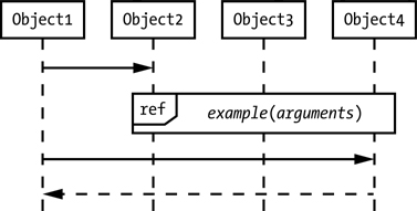
Figure 7-19: A ref sequence fragment example
This corresponds to a call to a subroutine (procedure or function) in code.
7.1.13.2 consider and ignore
The consider sequence fragment lists all messages that are valid within a section of the sequence diagram; all other messages/operators are illegal. The ignore operator lists names of messages that are invalid within a section of the sequence diagram; all other operators/messages are legal.
consider and ignore work either as operators in conjunction with an existing sequence fragment or as sequence fragments by themselves. A consider or ignore operator takes the following form:
consider{ comma-separated-list-of-operators }
ignore{ comma-separated-list-of-operators }
The consider and ignore operators may appear after the sd name title in an interaction occurrence (see Figure 7-20), in which case they apply to the entire diagram.

Figure 7-20: A consider operator example
You may also create a sequence fragment within another sequence diagram and label that fragment with a consider or ignore operation. In that case, consider or ignore applies only to the messages within the specific sequence fragment (see Figure 7-21).

Figure 7-21: An ignore sequence fragment example
If these fragment types seem strange, consider creating a very generic ref fragment that handles only certain messages, but then referencing that ref from several different places that might pass along unhandled messages along with the handled ones. By adding a consider or ignore operator to the ref, you can have the fragment simply ignore the messages it doesn’t explicitly handle, which allows you to use that ref without having to add any extra design to the system.
7.1.13.3 assert
The assert sequence fragment tells the system implementer that the messages within it are valid only if some guard condition evaluates to true. At the end of the assert fragment, you typically provide some sort of Boolean condition (the guard condition) that must be true once the sequence is complete (see Figure 7-22). If the condition isn’t true after the assert fragment has finished executing, the design can’t guarantee correct results. The assert reminds the engineer to verify that this condition is indeed true by, for example, using a C++ assert macro invocation (or something similar in other languages, or even just an if statement).

Figure 7-22: An assert sequence fragment example
In C/C++ you’d probably implement the sequence in Figure 7-22 using code like this:
Object3->msg1(); // Inside example
Object4->msg2(); // Inside Object3::msg1
assert( condition == TRUE ); // Inside Object3::msg1
7.1.13.4 loop
The loop sequence fragment indicates iteration. You place the loop operator in the penta-rectangle associated with the sequence fragment, and may also include a guard condition enclosed in brackets at the top of the sequence fragment. The combination of the loop operator and guard condition controls the number of iterations.
The simplest form of this sequence fragment is the infinite loop, consisting of the loop operator without any arguments and without a guard condition (see Figure 7-23). Most “infinite” loops actually aren’t infinite, but terminate with a break sequence fragment when some condition is true (we’ll discuss the break sequence in the next section).

Figure 7-23: An infinite loop
The loop in Figure 7-23 is roughly equivalent to the following C/C++ code:
// This loop appears inside Object3::msg1
for(;;)
{
Object4->msg2();
} // endfor
Or, alternatively:
while(1)
{
Object4->msg2()
} // end while
NOTE
Personally, I prefer the following:
#define ever ;;
.
.
.
for(ever)
{
Object4->msg2();
} // endfor
I feel this is the most readable solution. Of course, if you’re “anti-macro at all costs,” you would probably disagree with my choice for an infinite loop!
Definite loops execute a fixed number of times and can appear in two forms. The first is loop(integer), which is shorthand for loop(0, integer); that is, it will execute a minimum of zero times and a maximum of integer times. The second is loop(minInt, maxInt), which indicates that the loop will execute a minimum of minInt times and a maximum of maxInt times. Without a guard condition, the minimum count is irrelevant; the loop will always execute maxInt times. Therefore, most definite loops use the form loop(integer) where integer is the number of iterations to perform (see Figure 7-24).
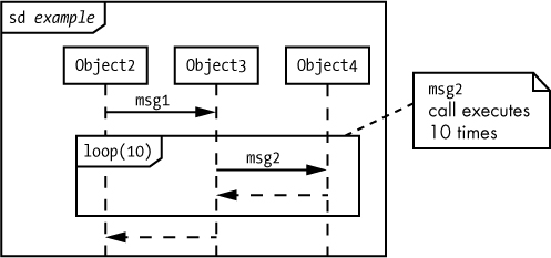
Figure 7-24: A definite loop
The loop in Figure 7-24 is roughly equivalent to the following C/C++ code:
// This code appears inside Object3::msg1
for( i = 1; i<=10; ++i )
{
Object4->msg2();
} // end for
You can also use the multiplicity symbol * to denote infinity. Therefore, loop(*) is equivalent to loop(0, *) which is equivalent to loop (in other words, you get an infinite loop).
An indefinite loop executes an indeterminate2 number of times (corresponding to while, do/while, repeat/until, and other loop forms in programming languages). Indefinite loops include a guard condition as part of the loop sequence fragment,3 meaning the loop sequence fragment will always execute the loop minInt times (zero times if minInt is not present). After minInt iterations, the loop sequence fragment will begin testing the guard condition and continue iterating only while the guard condition is true. The loop sequence fragment will execute at most maxInt iterations (total, not in addition to the minInt iterations). Figure 7-25 shows a traditional while-type loop that executes a minimum of zero times and a maximum of infinity times, as long as the guard condition ([cond == true]) evaluates to true.
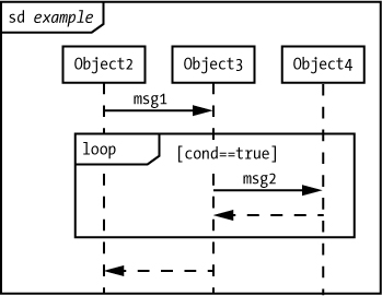
Figure 7-25: An indefinite while loop
The loop in Figure 7-25 is roughly equivalent to the following C/C++ code:
// This code appears inside Object3::msg1
while( cond == TRUE )
{
Object4->msg2();
} // end while
You can create a do..while loop by setting the minInt value to 1 and the maxInt value to *, and then specifying the Boolean expression to continue loop execution (see Figure 7-26).

Figure 7-26: An indefinite do..while loop
The loop in Figure 7-26 is roughly equivalent to the following C/C++ code:
// This code appears inside Object3::msg1
do
{
Object4->msg2();
} while( cond == TRUE );
It’s possible to create many other complex loop types, but I’ll leave that as an exercise for interested readers.
7.1.13.5 break
The break sequence fragment consists of the word break in a penta-rectangle along with a guard condition. If the guard condition evaluates to true, then the system executes the sequence inside the break sequence fragment, after which control immediately exits the enclosing sequence fragment. If the enclosing sequence fragment is a loop, control immediately executes to the first message past the loop (like a break statement in languages like Swift, C/C++, and Java). Figure 7-27 provides an example of such a loop.
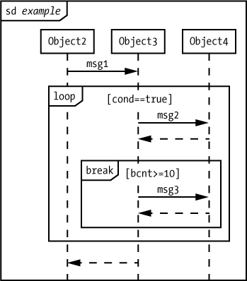
Figure 7-27: An example of the break sequence fragment
The loop in Figure 7-27 is roughly equivalent to the following C++ code fragment:
// This code appears inside Object3::msg1
while( cond == TRUE )
{
Object4->msg2();
if( bcnt >= 10 )
{
Object4->msg3();
break;
} // end if
Object4->msg4();
} // end while loop
If the most recent break-compatible enclosing sequence is a subroutine, not a loop, the break sequence fragment behaves like a return from a subroutine operation.
7.1.13.6 opt and alt
The opt and alt sequence fragments allow you to control the execution of a set of messages with a single guard condition—particularly if the values of the components making up the guard condition could change over the execution of the sequence.
The opt sequence fragment is like a simple if statement without an else clause. You attach a guard condition and the system will execute the sequence contained within the opt fragment only if the guard condition evaluates to true (see Figure 7-28).

Figure 7-28: An example of the opt sequence fragment
The example in Figure 7-28 is roughly equivalent to the following C/C++ code:
// Assumption: Class2 is Object2's data type. Because control
// transfers into the Object2 sequence at the top of its
// lifeline, example must be a member function of Object2/Class2
void Class2::example( void )
{
Object3->msg1();
} // end example
--snip--
// This code appears in Object3::msg1
if( cond == TRUE )
{
Object4->msg2();
} // end if
For more complex logic, use the alt sequence fragment, which acts like an if/else or switch/case. To create an alt sequence fragment, you combine several rectangles, each with its own guard condition and an optional else, to form a multiway decision (see Figure 7-29).
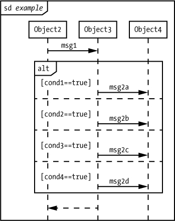
Figure 7-29: An alt sequence fragment
The interaction occurrence in Figure 7-29 is roughly equivalent to the following code:
// Assumption: Class2 is Object2's data type. Because control
// transfers into the Object2 sequence at the top of its
// lifeline, example must be a member function of Object2/Class2
void Class2::example( void )
{
Object3->msg1();
} // end example
--snip--
// This code appears in Object3::msg1
if( cond1 == TRUE )
{
Object4->msg2a();
}
else if( cond2 == TRUE )
{
Object4->msg2b();
}
else if( cond3 == TRUE )
{
Object3->msg2c();
}
else
{
Object4->msg2d();
} // end if
7.1.13.7 neg
You use a neg sequence fragment to enclose a sequence that will not be part of the final design. Effectively, using neg comments out the enclosed sequence. Why even include a sequence if it’s not going to be part of the design? There are at least two good reasons: code generation and future features.
Although, for the most part, UML is a diagramming language intended to help with system design prior to implementation in a programming language like Java or Swift, there are certain UML tools that will convert UML diagrams directly into code. During development, you might want to include some diagrams that illustrate something but are not yet complete (certainly not to the point of producing executable code). In this scenario, you could use the neg sequence fragment to turn off the code generation for those sequences that aren’t quite yet ready for prime time.
Even if you don’t intend to generate code directly from a UML diagram, you might want to use the neg for future features. When you hand your UML diagrams off to an engineer to implement the design, they represent a contract that says, “This is how the code is to be written.” Sometimes, though, you’ll want your diagrams to show features that you plan to include in a future version of the software, but not in the first (or current) version. The neg sequence fragment is a clean way to tell the engineer to ignore that part of the design. Figure 7-30 shows a simple example of the neg sequence fragment.
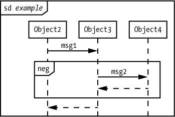
Figure 7-30: An example of the neg sequence fragment
The example in Figure 7-30 is roughly equivalent to the following C/C++ code:
// Assumption: Class2 is Object2's data type. Because control
// transfers into the Object2 sequence at the top of its
// lifeline, example must be a member function of Object2/Class2
void Class2::example( void )
{
Object3->msg1();
} // end example
7.1.13.8 par
The par sequence fragment, an example of which is shown in Figure 7-31, states that the enclosed sequences4 (operations) can be executed in parallel with each other.
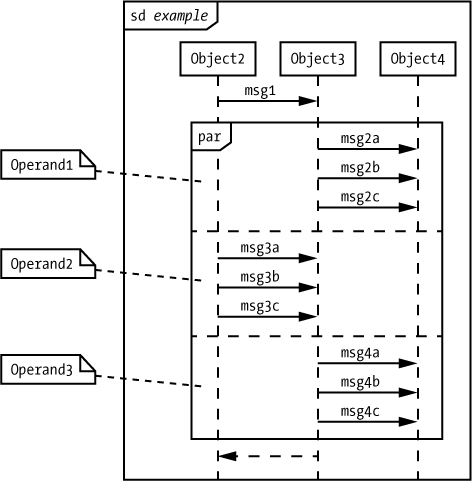
Figure 7-31: An example of the par sequence fragment
Figure 7-31 shows three operands: the sequence with {msg2a, msg2b, msg2c}, the sequence with {msg3a, msg3b, msg3c}, and the sequence with {msg4a, msg4b, msg4c}. The par sequence fragment requires that the operations within a given sequence must execute in the order in which they appear (for example, msg2a, then msg2b, then msg2c). However, the system is free to interleave operations from different operands as long as it maintains the internal order of those operands. So, in Figure 7-31, the order {msg2a, msg3a, msg3b, msg4a, msg2b, msg2c, msg4b, msg4c, msg3c} is legitimate, as is {msg4a, msg4b, msg4c, msg3a, msg3b, msg3c, msg2a, msg2b, msg2c}, because the ordering of the enclosed sequences matches. However, {msg2a, msg2c, msg4a, msg4b, msg4c, msg3a, msg3b, msg3c, msg2b} is not legitimate because msg2c occurs before msg2b (which is contrary to the ordering specified in Figure 7-31).
7.1.13.9 seq
The par sequence fragment enforces the following restrictions:
- The system maintains the ordering of the operations within an operand.
- The system allows operations on different lifelines from different operands to execute in any order.
And the seq sequence adds another:
- Operations on the same lifeline in different operands must execute in the order in which they appear in the diagram (from top to bottom).
In Figure 7-32, for example, Operand1 and Operand3 have messages that are sent to the same object (lifeline). Therefore, in a seq sequence fragment, msg2a, msg2b, and msg2c must all execute before msg4a.
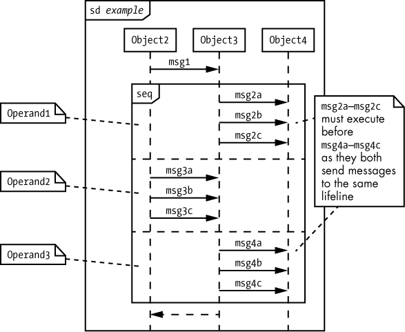
Figure 7-32: An example of the seq sequence fragment
Figure 7-32 shows a stand-alone seq sequence fragment. In typical usage, however, a seq sequence fragment will appear inside a par to control the execution sequence of a portion of the par’s operands.
7.1.13.10 strict
The strict sequence fragment forces the operations to occur in the sequence they appear in each operand; interleaving of operations between operands is not allowed. The format for a strict sequence fragment is similar to that of par and seq (see Figure 7-33).

Figure 7-33: An example of the strict sequence fragment
The strict parallel operation allows the operands to execute in any order, but once a given operand begins execution, all the operations within it must complete in the sequence specified before any other operand can begin executing.
In Figure 7-33, there are six different operation sequences possible: {Operand1, Operand2, Operand3}; {Operand1, Operand3, Operand2}; {Operand2, Operand1, Operand3}; {Operand2, Operand3, Operand1}; {Operand3, Operand1, Operand2}; and {Operand3, Operand2, Operand1}.
However, operations internal to the operands cannot interleave, and must execute from top to bottom.
7.1.13.11 region
In the section “Extending UML Activity Diagrams” on page 99, I used the example of a home-brew critical section in an activity diagram to demonstrate how to extend UML for your own purposes. I pointed out why this is a bad idea (reread that section for the details), and mentioned there is another way to achieve what you want to do using standard UML: the region sequence fragment. UML activity diagrams don’t support critical sections, but sequence diagrams do.
The region sequence fragment specifies that once execution enters the region, no other operations in the same parallel execution context can be interleaved until it completes execution. The region sequence fragment must always appear within some other parallel sequence fragment (generally par or seq; technically it could appear inside strict, though ultimately this would serve no purpose).
As an example, consider Figure 7-34—the system is free to interleave the execution of any operand’s messages, subject to the rules given for the par sequence fragment, but once the system enters the critical region (with the execution of the msg4a operation), no other threads in the par sequence fragment can execute.
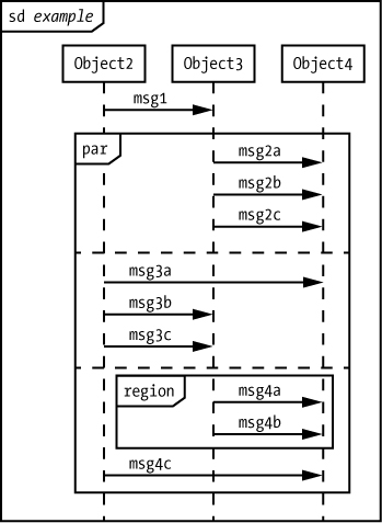
Figure 7-34: The region sequence fragment
7.2 Collaboration Diagrams
Collaboration (or communication) diagrams provide the same information as sequence diagrams but in a slightly more compact form. Rather than drawing arrows between lifelines, in collaboration diagrams we draw message arrows directly between objects, and attach numbers to each message to indicate the sequence (see Figure 7-35).
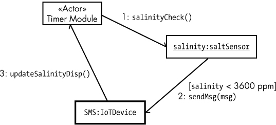
Figure 7-35: A collaboration diagram
The diagram in Figure 7-35 is roughly equivalent to the sequence diagram in Figure 7-9 (without the time constraint of 10 minutes). In Figure 7-35 the salinityCheck message executes first, sendMsg executes second, and updateSalinityDisplay executes last.
Figure 7-36 shows a more complex collaboration diagram that better demonstrates the compactness of this option. The six messages sent in this example would require six lines in a sequence diagram but here require only three communication links.

Figure 7-36: A more complex collaboration diagram
NOTE
Having both collaboration and sequence diagrams is probably an artifact of merging different systems together when UML was created. Which one you use is really just a matter of personal preference. Keep in mind, however, that as the diagrams become more complex, collaboration diagrams become harder to follow.
7.3 For More Information
Bremer, Michael. The User Manual Manual: How to Research, Write, Test, Edit, and Produce a Software Manual. Grass Valley, CA: UnTechnical Press, 1999. A sample chapter is available at http://www.untechnicalpress.com/Downloads/UMM%20sample%20doc.pdf.
Larman, Craig. Applying UML and Patterns: An Introduction to Object-Oriented Analysis and Design and Iterative Development. 3rd ed. Upper Saddle River, NJ: Prentice Hall, 2004.
Miles, Russ, and Kim Hamilton. Learning UML 2.0: A Pragmatic Introduction to UML. Sebastopol, CA: O’Reilly Media, 2003.
Pender, Tom. UML Bible. Indianapolis: Wiley, 2003.
Pilone, Dan, and Neil Pitman. UML 2.0 in a Nutshell: A Desktop Quick Reference. 2nd ed. Sebastopol, CA: O’Reilly Media, 2005.
Roff, Jason T. UML: A Beginner’s Guide. Berkeley, CA: McGraw-Hill Education, 2003.
Tutorials Point. “UML Tutorial.” https://www.tutorialspoint.com/uml/.